


KM-630MRH
Table of contents
 Loading...
73114
HOSHIZAKI
MODULAR CRESCENT CUBER
SER VICE MANUAL
KM-630MAH
KM-630MWH
KM-630MRH
MODEL
JUNE 23, 2004
NO.:
ISSUED:

2
IMPORTANT
Only qualified service technicians should attempt to service or maintain this icemaker.
No service or maintenance should be undertaken until the technician has thoroughly
read this Service Manual.
HOSHIZAKI AMERICA, INC.
618 Highway 74 South
Peachtree City, GA 30269
Attn: HOSHIZAKI Technical Support Department
Phone: 1-800-233-1940 Technical Service
(770) 487-2331
Fax: (770) 487-3360
NOTE: To expedite assistance, all correspondence/communication MUST include the following
information:
• Model Number
• Serial Number
• Complete and detailed explanation of the problem
HOSHIZAKI provides this manual primarily to assist qualified service technicians in the
service and maintenance of the icemaker.
Should the reader have any questions or concerns which have not been satisfactorily
addressed, please call or write to the HOSHIZAKI Technical Support Depar tment for
assistance.

3
CONTENTS
I. SPECIFICATIONS............................................................................................................ 5
1. KM-630MAH................................................................................................................ 5
2a. KM-630MWH Serial #L00001D - M20270B................................................................ 6
2b. KM-630MWH Serial #M20301E - ............................................................................... 7
3. KM-630MRH................................................................................................................ 8
4. CONDENSER UNIT .................................................................................................... 9
URC-6F...................................................................................................................... 9
II. GENERAL INFORMATION............................................................................................. 11
1. CONSTRUCTION ...................................................................................................... 11
[a] KM-630MAH........................................................................................................ 11
[b] KM-630MWH....................................................................................................... 12
[c] KM-630MRH........................................................................................................ 13
2. CONTROLLER BOARD............................................................................................. 14
[a] SOLID-STATE CONTROL ................................................................................... 14
[b] CONTROLLER BOARD...................................................................................... 14
[c] SEQUENCE ........................................................................................................ 18
[d] CONTROLS AND ADJUSTMENTS ................................................................... 21
[e] CHECKING THE CONTROLLER BOARD ......................................................... 25
3. MECHANICAL BIN CONTROL.................................................................................. 26
[a] PROXIMITY SWITCH.......................................................................................... 26
[b] EXPLANATION OF OPERATION........................................................................ 26
[c] TROUBLESHOOTING (MECHANICAL BIN CONTROL ONLY).......................... 27
III. TECHNICAL INFORMATION........................................................................................ 28
1. WATER CIRCUIT AND REFRIGERANT CIRCUIT.................................................... 28
[a] KM-630MAH........................................................................................................ 28
[b] KM-630MWH....................................................................................................... 29
[c] KM-630MRH........................................................................................................ 30
2. WIRING DIA GRAMS .................................................................................................. 31
[a1] KM-630MAH (with auxiliary codes L-0, M-0, and M-1) and KM-630MWH
(with auxiliary codes L-0, M-0, M-1, and M-2).................................................... 31
[a2] KM-630MAH (with auxiliary codes M-2 and after) and KM-630MWH
(with auxiliary codes M-3 and after)................................................................... 32
[b1] KM-630MRH (with auxiliary codes L-0, M-0, M-1) ............................................. 33
[b2] KM-630MRH (with auxiliary codes M-2 and after) ............................................. 34
3. TIMING CHART.......................................................................................................... 35
4. PERFORMANCE DATA ............................................................................................. 37
[a] KM-630MAH........................................................................................................ 37
[b1] KM-630MWH Serial #L00001D - M20270B ...................................................... 38
[b2] KM-630MWH Serial #M20301E - ...................................................................... 39
[c] KM-630MRH........................................................................................................ 40
• Please review this manual. It should be read carefully before the icemaker is serviced or
maintenance operations performed. Only qualified service technicians should service and
maintain the icemaker. This manual should be made available to the technician prior to
service or maintenance.

4
IV. SERVICE DIAGNOSIS ................................................................................................. 41
1. NO ICE PRODUCTION.............................................................................................. 41
2. EVAPORATOR IS FROZEN UP................................................................................. 44
3. LOW ICE PRODUCTION ........................................................................................... 45
4. ABNORMAL ICE ........................................................................................................ 45
5. OTHERS .................................................................................................................... 45
V. REMOVAL AND REPLACEMENT OF COMPONENTS................................................ 46
1. SERVICE FOR REFRIGERANT LINES .................................................................... 46
[a] REFRIGERANT RECOVERY ............................................................................. 46
[b] EVACUATION AND RECHARGE [R-404A] ........................................................ 46
2. BRAZING ................................................................................................................... 47
3. REMOVAL AND REPLACEMENT OF COMPRESSOR ............................................ 48
4. REMOVAL AND REPLACEMENT OF DRIER ........................................................... 50
5. REMOVAL AND REPLACEMENT OF EXPANSION VALVE...................................... 5 0
6. REMOVAL AND REPLACEMENT OF HOT GAS VALVE AND LINE VALVE ............. 51
7. REMOVAL AND REPLACEMENT OF EVAPORATOR.............................................. 53
8. REMOVAL AND REPLACEMENT OF WATER REGULATING VALVE -
WA TER-COOLED MODEL ONLY.............................................................................. 54
9. ADJUSTMENT OF WATER REGULATING VALVE - WATER-COOLED
MODEL ONLY ........................................................................................................... 55
10. REMOVAL AND REPLACEMENT OF CONDENSING PRESSURE
REGULATOR (C.P.R.) - REMO TE AIR-COOLED MODEL ONLY ............................ 56
11. REMOVAL AND REPLACEMENT OF THERMISTOR............................................. 57
12. REMOVAL AND REPLACEMENT OF FAN MOTOR ............................................... 58
13. REMOVAL AND REPLACEMENT OF WATER VALVE ............................................ 5 9
14. REMOVAL AND REPLACEMENT OF PUMP MOTOR ............................................ 59
15. REMOVAL AND REPLACEMENT OF SPRAY TUBES ........................................... 6 0
VI. CLEANING AND MAINTENANCE INSTRUCTIONS................................................... 6 1
1. PREPARING THE ICEMAKER FOR LONG STORAGE ............................................. 6 1
2. CLEANING AND SANITIZING PROCEDURES ........................................................ 63
[a] CLEANING PROCEDURE ................................................................................. 64
[b] SANITIZING PROCEDURE................................................................................ 66
3. MAINTENANCE......................................................................................................... 67
5
I. SPECIFICATIONS
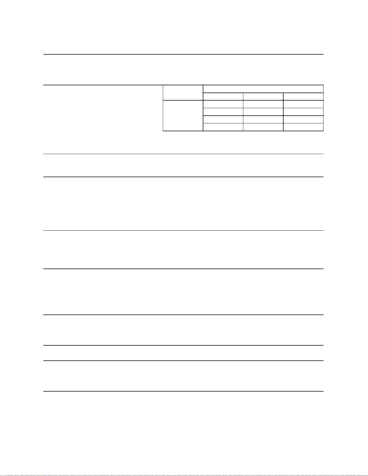
1. KM-630MAH
Note: We reserve the right to make changes in specifications and design without prior notice.
AC SUP P LY VOLTAGE 208-230/60/1 (3 wire wit h neut ral for 115V)
AM P E RA GE 7.5 A ( 5 Mi n. Freeze A T 104°F / WT 80°F)
MINIMUM CIRCUIT AMPACITY 15 A
MAXIMUM FUSE SIZE 15 A
APPROXIMATE ICE PRODUCTION Ambient WATER TEMP. (°F)
PER 24 HR. Temp.(°F) 50 70 90
lbs . /day ( k g/ day ) 70 *600 (272) 562 (255) 514 (233)
Reference wi t hout * marks 80 571 (259) 512 (232) 466 (211)
90 562 (255) * 470 (213) 422 (191)
100 554 (251) 459 (208) 378 (171)
SHAPE OF ICE Cresc ent Cube
ICE PRODUCTION PER CYCLE 14.3 lbs. (6. 5 k g) 720 pc s.
APPROXIMATE STORAGE CAPACITY N/A
ELECTRIC & WATER CONSUMPTION 90/70°F 70/50°F
ELECTRIC W (kWH/100 lbs .) 1332 (6.8) 1250 (5.0)
WATER gal./ 24HR (gal./100 lbs. ) 157 (33.4) 341 (56. 9)
EXTERIOR DIMENS IONS (WxDx H) 22" x 27-1/ 2" x 37-1/2" (560 x 695 x 950 mm )
EXTERIOR FINISH St ai nless Steel, Gal vanized Steel (Rear)
WEIGHT Net 154 lbs . ( 70 kg ), S hi ppi ng 185 lbs. (84 kg)
CONNECTIONS - ELE CTRIC Permanent - Connec t i on
- WATER SUPPLY Inlet 1/2" FPT
- DRAIN Outlet 3/4" FPT
3/8" OD P i pe
CUBE CONTROL SYSTEM Float Switch
HARVESTING CONTROL SYSTEM Hot Gas and Water, Thermistor and Timer
ICE MAK ING W ATER CONTROL Timer Cont roll ed. Overfl ow P i pe
COOLING WA TE R CO NTROL N/A
BIN CONTROL SYSTEM Proximity Switch with Delay
COMPRESSOR Hermetic , Model RS64C1E-CAV
CONDENSER Air-c ool ed, F i n and t ube t ype
EV A PORATOR V ert i cal type, S t ai nl ess S teel and Copper
REFRIGERANT CONTROL Thermos tatic Expansion V al ve
REFRIGERANT CHARGE R-404A, 1 lb. 7.6 oz. ( 670 g )
DESIGN PRE S SURE High 467 PS IG, Low 230 PSIG
P.C. BOA RD CIRCUIT PRO TE CTION High V olta ge Cut-out ( Int er nal )
COMPRESSOR PROTECTION Auto-reset Overload P rotector ( Internal )
REFRIGERANT CIRCUIT PROTECTION Auto-reset High Pressure Control Switch
LOW W ATER PROTECTION Float Switch
ACCESSORIES -SUPPLIED N/A
-REQUIRED Ice Storage Bin
OPERATING CONDITIONS VOLTAGE RANGE 187 - 253 V
AMBIENT TEMP. 45 -100° F
WATER SUPPLY TEMP. 45 - 90° F
WATER SUPPLY PRESSURE 10 - 113 PSIG
6
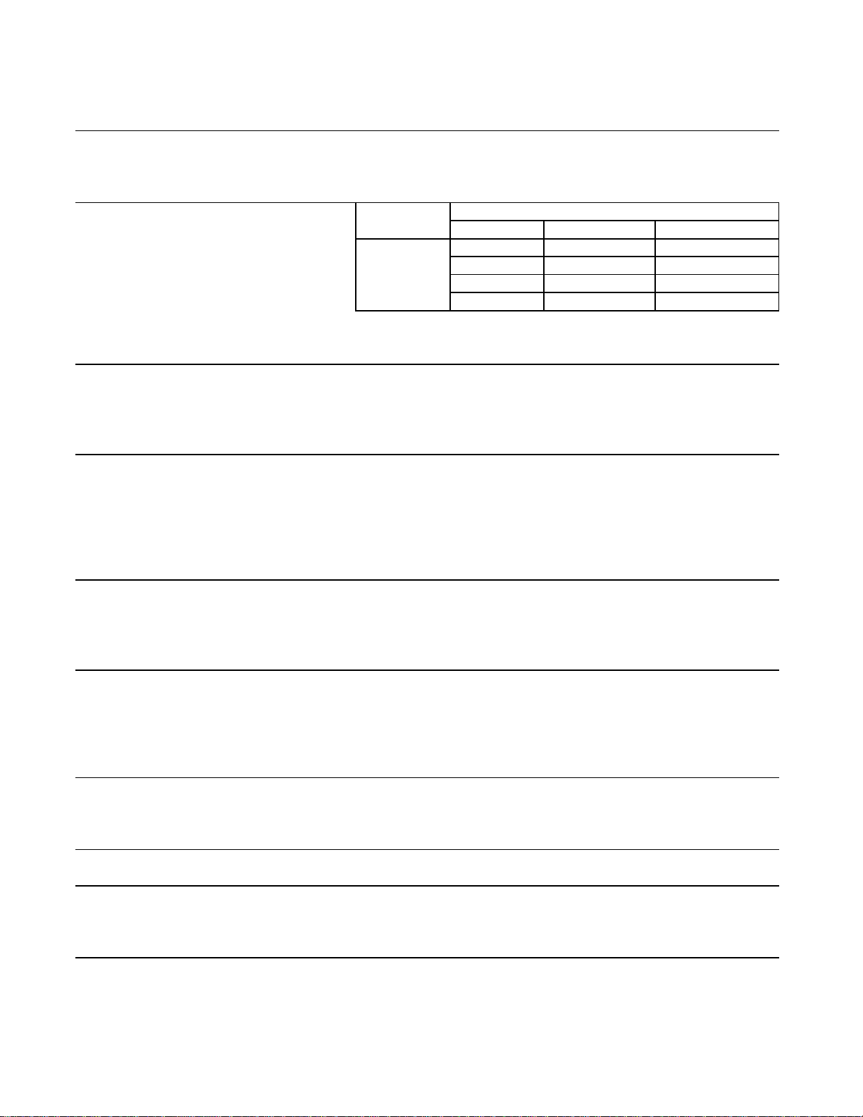
2a. KM-630MWH Serial #L00001D - M20270B
Note: We reserve the right to make changes in specifications and design without prior notice.
AC SUPPLY VOLTAGE
AMPERAGE
MINIMUM CIRCUIT AMPACITY
MAXIMUM FUSE SIZE
APPROXIMATE ICE PRODUCTION Ambient WATER TEMP. (°F)
PE R 24 HR. Temp.(°F) 50 70
lbs . /day ( k g/ day ) 70 *619 (281) 596 (270)
Referenc e wit hout *marks 80 602 (273) 566 (257)
90 596 (270) *541 (245)
100 589 (267) 533 (242)
SHAPE OF ICE Crescent Cube
ICE PRODUCTION PER CYCLE 14.3 lbs. (6. 5 k g) 720 pc s.
APPROXIMATE STORAGE CAPACITY N/A
ELE CTRIC & WATER CONSUMP TION 90/70°F 70/50°F
ELECTRIC W (kWH/100 lbs.) 1306 (5.7) 1290 (5.0)
WATER gal./ 24HR (gal./100 lbs.) 196 (36.3) 335 (54.1)
WATER COOLED CONDENSER 844 (156) 458 (74)
gal./24HR (gal./100 lbs.)
EXTERIOR DIMENS IONS (W xDxH) 22" x 27-1/ 2" x 37-1/2" (560 x 695 x 950 mm )
EXTERIOR FINISH St ai nless Steel, G alvanized Steel (Rear)
WEIGHT Net 154 lbs . ( 70 kg ), Shipping 185 lbs . (84 kg)
CONNECTIONS - ELE CTRIC Permanent - Connec t i on
- WATER SUPPLY Inlet 1/2" FPT
- DRAIN Outlet 3/4" FPT
3/8" OD P i pe
CUBE CONTROL SYSTEM Float Switc h
HARVESTING CONTROL SYSTE M Hot Gas and Wat er, Thermistor and Timer
ICE MAK ING W ATER CONTROL Timer Cont roll ed. Overflow Pi pe
COOLING WA TE R CO NTROL N/A
BIN CO NTROL SYSTEM Pro xim ity S witch wi th Del ay
COMPRE SSO R Hermet ic, Mo de l RS64C1E-CA V
CONDENSER Water-cooled, Tube in tube t ype
EV A PORATOR V ert i cal type, S tainles s St eel and Copper
REFRIGERA NT CONTROL Thermostatic Ex pansion Valve
REFRIGERA NT CHARGE R-404A, 1 lb. 3 oz. ( 525 g )
DESIGN PRESSURE High 427 PSIG, Low 230 PSIG
P.C. BOA RD CIRCUIT PRO TE CTION Hi g h Vol tage Cut-out ( Int ern al )
COMPRE S SOR PROTECTION A uto-reset Overload Protector ( Internal )
REF R IGERANT CIRCUIT PROTE CTION Aut o -re set High P re ss ur e Co ntrol Switch
LOW W ATER PROTECTION Float Switch
ACCESSORIES -SUPPLIED N/A
-REQUIRED Ice Storage Bin
OP ERATING CON DITIONS VO LTA G E RANG E
AMBIENT TEMP.
WATER SUPPLY TEMP.
WATER SUPPLY PRESSURE
208-230/60/1 (3 wire wit h neut ral for 115V)
6.5 A ( 5 M in. Freeze A T 104°F / WT 80°F)
15 A
45 -100° F
45 - 90° F
10 - 113 PSIG
187 - 253 V
533 (242)
507 (230)
476 (216)
Condenser Inlet 1/ 2" F P T
Condenser Outl et 3/8" FP T
90
563 (256)
15 A
7
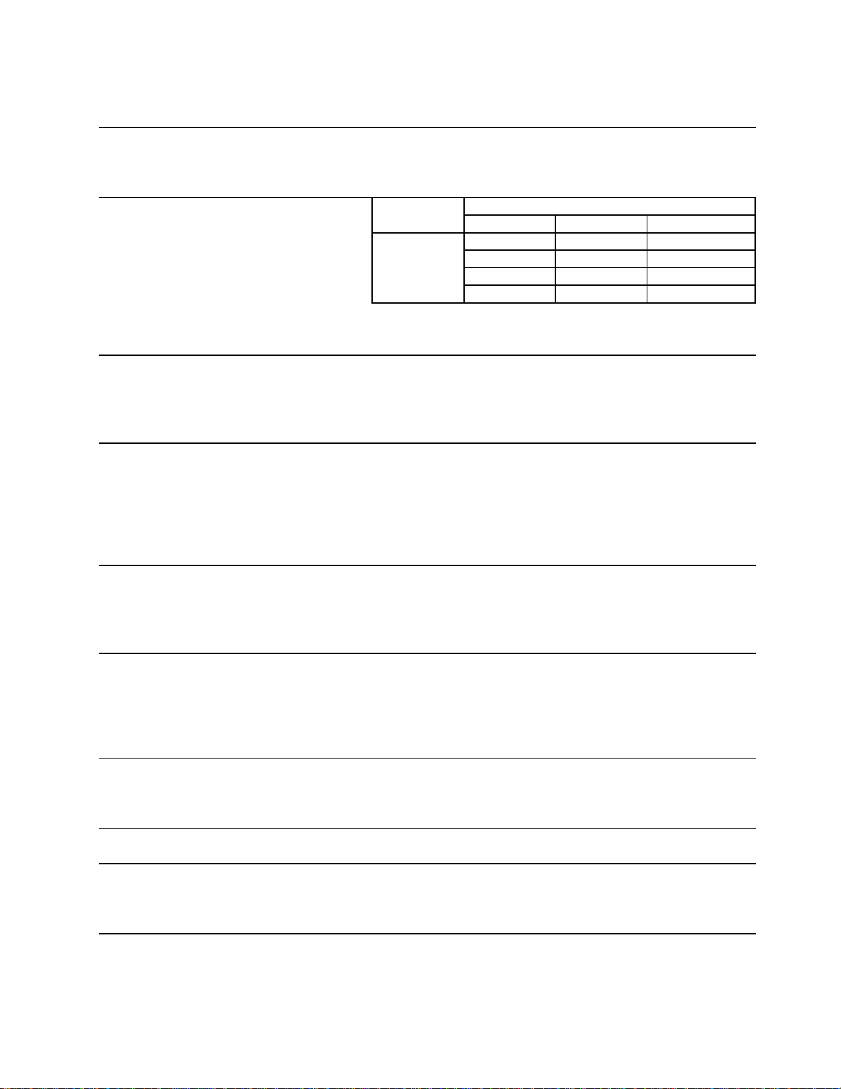
2b. KM-630MWH Serial #M20301E -
AC SUP P LY VOLTAGE 208-230/60/1 (3 wire wit h neut ral for 115V)
AM P E RA GE 6.5 A ( 5 Mi n. Freeze A T 104°F / WT 80°F)
MINIMUM CIRCUIT AMPACITY 15 A
MAXIMUM FUSE SIZE 15 A
APPROXIMATE ICE PRODUCTION Ambient WA TER TEMP. (°F)
PER 24 HR. Temp.(°F) 50 70 90
lbs . /day ( k g/ day ) 70 *621 (282) 603 (273) 563 (256)
Reference wi t hout * marks 80 607 (275) 578 (262) 532 (241)
90 603 (273) * 558 (253) 514 (233)
100 590 (268) 548 (248) 473 (215)
SHAPE OF ICE Cresc ent Cube
ICE PRODUCTION PER CYCLE 14.3 lbs. (6.5 kg) 720 pcs.
APPROXIMATE STORAGE CAPACITY N/A
ELECTRIC & WATER CONSUMPTION 90/70°F 70/50°F
ELECTRIC W (kWH/100 lbs .) 1279 (5.5) 1268 (4.9)
WATER gal./ 24HR (gal./100 lbs. ) 156 (27.9) 299 (48.1)
WATER COOLED CONDENSER 536 (96) 354 (57)
gal./24HR (gal./100 lbs.)
EXTERIOR DIMENS IONS (W xDxH) 22" x 27-1/ 2" x 37-1/2" (560 x 695 x 950 mm)
EXTERIOR FINISH St ai nless Steel, Gal vanized Steel (Rear)
WEIGHT Net 154 lbs . ( 70 kg ), Shi ppi ng 185 lbs. (84 kg)
CONNECTIONS - ELE CTRIC Permanent - Connec t i on
- WA TER S UPPLY Inlet 1/2" FPT Condenser Inlet 1/2" FPT
- DRAIN Outl et 3/ 4" FPT Condenser Outl et 3/8" FP T
3/8" OD P i pe
CUBE CONTROL SYSTEM Float Switch
HARVESTING CONTROL SYSTEM Hot Gas and Water, Thermistor and Timer
ICE MAK ING W ATER CONTROL Timer Controlled. O verfl ow P i pe
COOLING WA TE R CO NTROL Pre ss ur e Re g ul a tor
BIN CONTROL SYSTEM Proximity Switch with Delay
COMPRESSOR Hermetic , Model RS64C2E-CAV-219
CONDENSER Water-cooled, Tube in tube t ype
EV A PORATOR V ert i cal type, S t ai nl ess S teel and Copper
REFRIGERANT CONTROL Thermos tatic Ex pansion Valve
REFRIGERANT CHARGE R-404A, 1 lb. 4.3 oz. ( 575 g )
DESIGN PRE S SURE High 427 PSIG, Low 230 PSIG
P.C. BOA RD CIRCUIT PRO TE CTION Hi g h Voltage Cu t-out ( Inte rn al )
COMPRESSOR PROTECTION Auto-reset Overload Protector ( Int ernal )
REFRIGERANT CIRCUIT PROTECTION Auto-reset High Pressure Control Switch
LOW W ATER PROTECTION Float Switch
ACCESSORIES -SUPPLIED N/A
-REQUIRED Ice Storage Bin
OPERATING CONDITIONS VOLTAGE RANGE 187 - 253 V
AMBIENT TEMP. 45 -100° F
WATER SUPPLY TEMP. 45 - 90° F
WATER SUPP LY P RE S SURE 10 - 113 PSIG
Note: We reserve the right to make changes in specifications and design without prior notice.
8
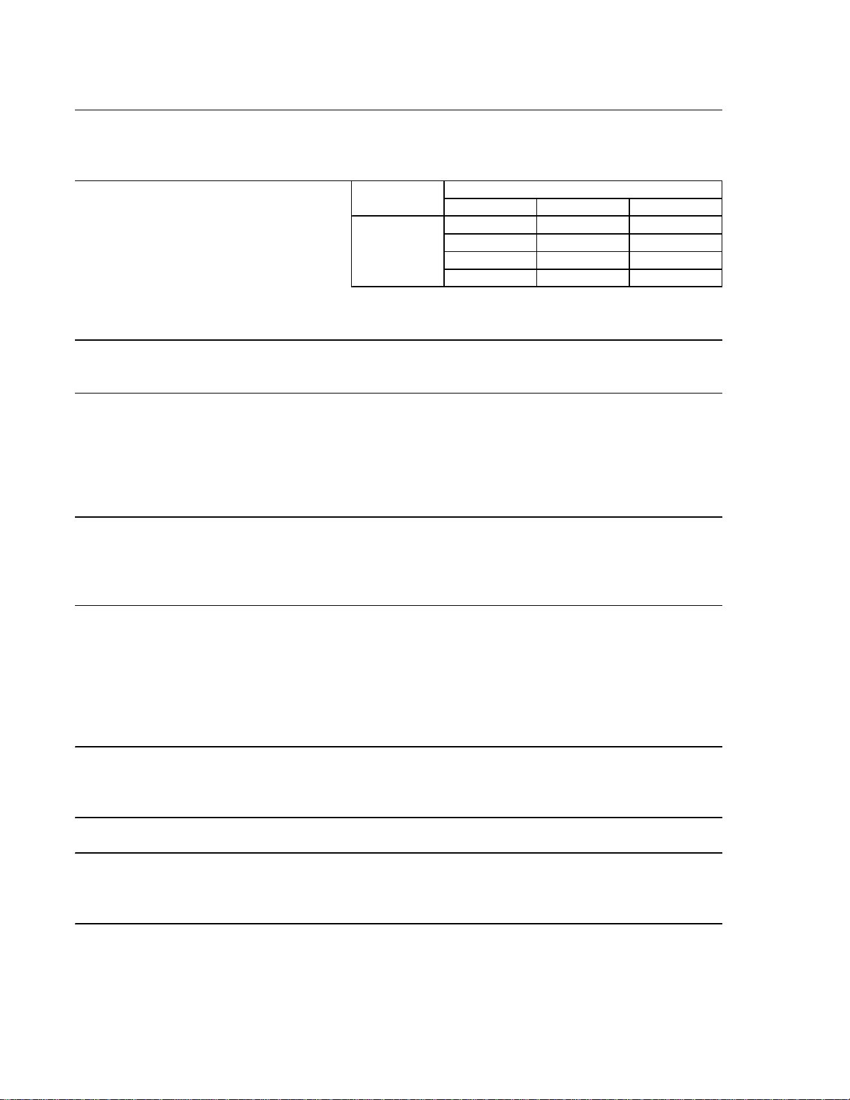
3. KM-630MRH
Note: We reserve the right to make changes in specifications and design without prior notice.
AC SUP P LY VOLTAGE 208-230/60/1 (3 wire wit h neut ral for 115V)
AM P E RA GE 6.5 A ( 5 Mi n. Freeze A T 104°F / WT 80°F)
MINIMUM CIRCUIT AMPACITY 15 A
MAXIMUM FUSE SIZE 15 A
APPROXIMATE ICE PRODUCTION Ambient WATER TEMP. (°F)
PER 24 HR. Temp.(°F) 50 70 90
lbs . /day ( k g/ day ) 70 *603 (274) 573 (260) 531 (241)
Reference wi t hout * marks 80 580 (263) 532 (242) 491 (223)
90 573 (260) * 499 (226) 457 (207)
100 564 (256) 489 (222) 418 (190)
SHAPE OF ICE Cresc ent Cube
ICE PRODUCTION PER CYCLE 14.3 lbs. (6.5 kg) 720 pcs.
APPROXIMATE STORAGE CAPACITY N/A
ELECTRIC & WATER CONSUMPTION 90/70°F 70/50°F
ELECTRIC W (kWH/100 lbs .) 1414 (6.8) 1332 (5.3)
WATER gal./ 24HR (gal./100 lbs. ) 166 (33.3) 323 (53.6)
EXTERIOR DIMENS IONS (WxDx H) 22" x 27-1/ 2" x 37-1/2" (560 x 695 x 950 mm)
EXTERIOR FINISH St ai nless Steel, Gal vanized Steel (Rear)
WEIGHT Net 154 lbs . ( 70 kg ), Shi ppi ng 185 lbs. (84 kg)
CONNECTIONS - ELE CTRIC Permanent - Connection
- WATER SUPPLY Inlet 1/2" FPT
- DRAIN Outlet 3/4" FPT
3/8" OD P i pe
CUBE CONTROL SYSTEM Float Switch
HARVESTING CONTROL SYSTEM Hot Gas and Water, Thermistor and Timer
ICE MAK ING W ATER CONTROL Timer Cont roll ed. Overfl ow P i pe
COOLING WA TE R CO NTROL N/A
BIN CONTROL SYSTEM Proximity Switch with Delay
COMPRESSOR Hermetic , Model RS64C1E-CAV
CONDENSER Air-c ool ed Remot e, Condenser Unit URC 6 F
EV A PORATOR V ert i cal type, S t ai nl ess S teel and Copper
REFRIGERANT CONTROL Thermos tatic Expansion V alve
Condensing P res sure Regulator on URC-6F
REFRIGERANT CHARGE R-404A, 4 lb. 4 oz. ( 1950 g )
( Icemak er 2 lbs. 6 oz . Cond. 1 lbs . 14 oz. )
DESIGN PRE S SURE High 467 PS IG, Low 230 PSIG
P.C. B O ARD CIRCUIT PROTE CTION Hi g h Voltage Cu t-out ( Inte rn al )
COMPRESSOR PROTECTION Auto-reset Overload Protector ( Int ernal )
REFRIGERANT CIRCUIT PROTECTION Auto-reset High Pressure Control Switch
LOW W ATER PROTECTION Float Switch
ACCESSORIES -SUPPLIED N/A
-REQUIRED Ice Storage Bin
OPERATING CONDITIONS VOLTAGE RANGE 187 - 253 V
AMBIENT TEMP. 45 -100° F
WATER SUPPLY TEMP. 45 - 90° F
WATER SUPPLY PRESSURE 10 - 113 PSIG
9
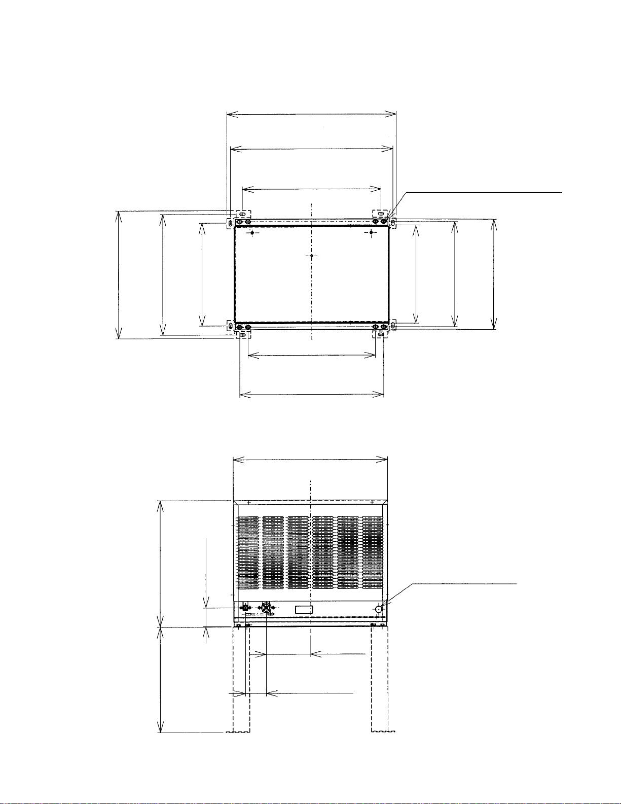
4. CONDENSER UNIT
URC-6F
24"
(610 mm.)
23-1/32"
(585 mm.)
19-11/16"
(500 mm.)
18-1/8"
(460 mm.)
20-15/32"
(520 mm.)
21-15/16"
(557 mm.)
7/8" DIA. HOLE
(23 mm. DIA.)
6-5/16"
(160 mm.)
2-15/16"
(75 mm.)
18-1/8"
(460 mm.)
6/16" x 3/4" (10 mm. x 20 mm.)
4 x 2 (SLOTTED HOLES)
17-1/8"
(435 mm.)
14-9/16"
(370 mm.)
14-1/8"
(358 mm.)
14-15/16"
(380 mm.)
15-11/16"
(398 mm.)
17-7/8"
(454 mm.)
2-1/2"
(63 mm.)
14-15/16"
(380 mm.)

10
Galvanized Steel
21-15/16" x 15-11/16" x 17-7/8"
(557 x 398 x 453.8 mm.)
R404A 1 lb. 2 oz. (505 g)
Net 61 lbs. (28 kg)
Shipping 68 lbs. (31 kg)
One Shot Couplings (Aeroquip)
Permanent Connection
Air-cooled
Condensing Pressure Regulator
Min. -20°F - Max. +122°F
(-29°C to +50°C)
Outdoor use
SPECIFICATIONS
EXTERIOR
DIMENSIONS (W x D x H)
REFRIGERANT CHARGE
WEIGHT
CONNECTIONS
REFRIGERANT
ELECTRICAL
CONDENSER
HEAD PRESSURE CONTROL
AMBIENT CONDITION
MODEL: URC-6F
11
II. GENERAL INFORMATION
1. CONSTRUCTION
[a] KM-630MAH
Spray Tubes Water Supply Inlet
Control Switch
Condenser
Hot Gas Valve
Expansion Valve Fan Motor
Condenser
Compressor
Drier
Float Switch
Control Box
Water Pump
Bin Control Thermostat
(except models with
Mechanical Bin Control)
Mechanical
Bin Control
(except models
with Thermostat)
12
[b] KM-630MWH
Spray Tubes Water Supply Inlet
Control Switch
Water Regulator
Expansion Valve Hot Gas Valve
Compressor
Float Switch Drier
Water Pump Control Box
Bin Control Thermostat
(except models with
Mechanical Bin Control)
Mechanical
Bin Control
(except models
with Thermostat)
13
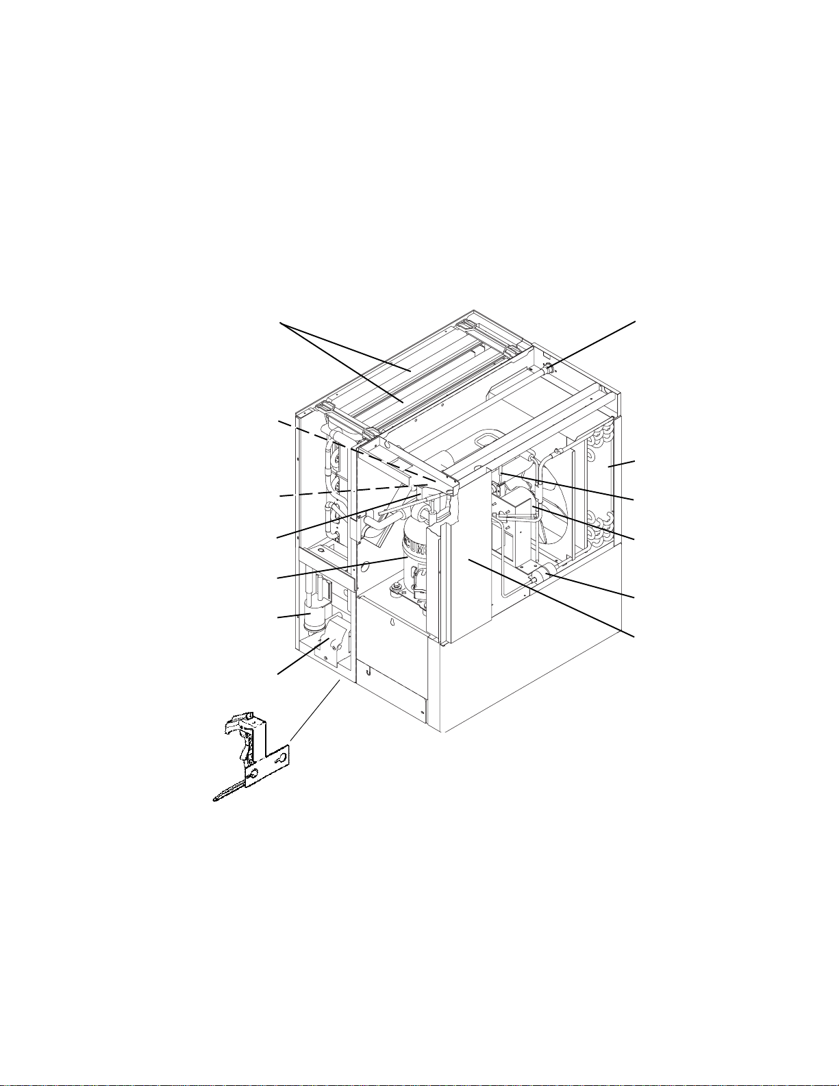
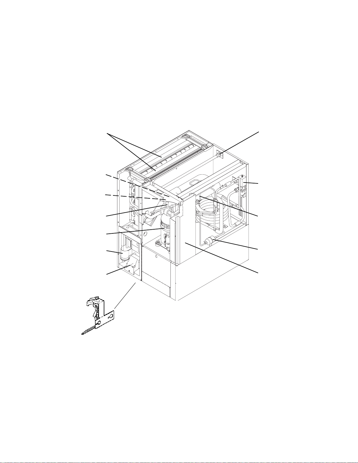
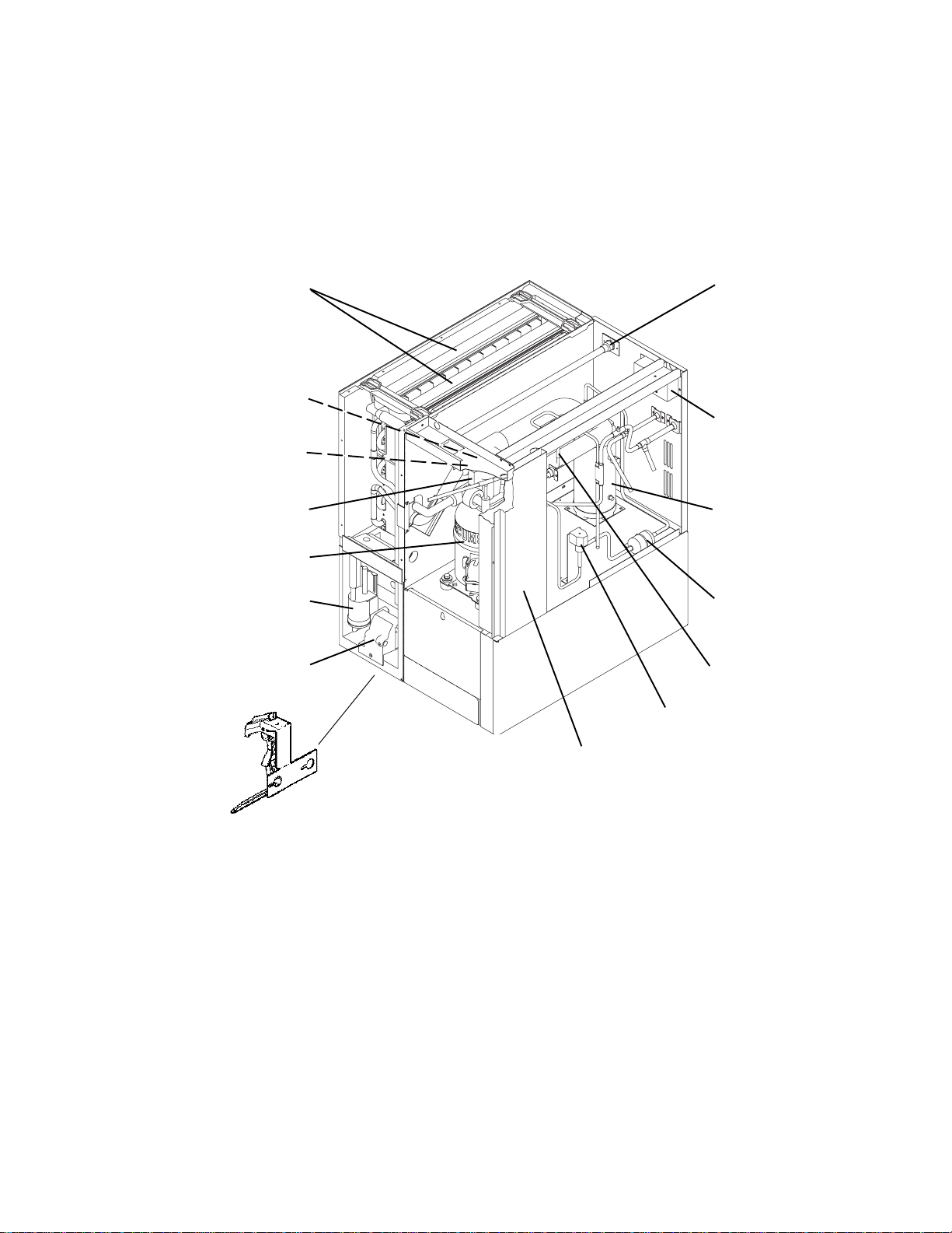
[c] KM-630MRH
Spray Tubes Water Supply Inlet
Control Switch
Junction Box
Expansion Valve Receiver Tank
Compressor
Float Switch Drier
Water Pump Hot Gas Valve
Line Valve
Control Box
Bin Control Thermostat
(except models with
Mechanical Bin Control)
Mechanical
Bin Control
(except models
with Thermostat)

14
2. CONTROLLER BOARD
[a] SOLID-STATE CONTROL
1) A HOSHIZAKI exclusive solid-state control is employed in Modular Crescent Cubers.
2) A Printed Circuit Board (hereafter called “Controller Board”) includes a stable and high
quality control system.
3) All models are pretested and factory-adjusted.
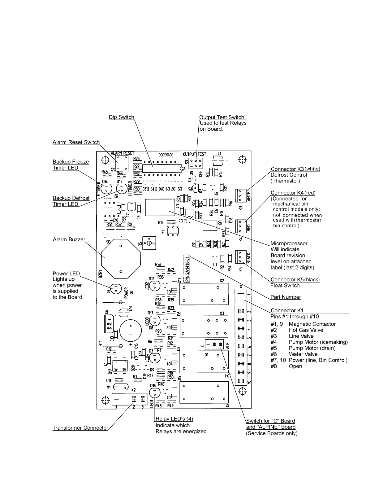
[b] CONTROLLER BOARD
CAUTION
1. Fragile, handle very carefully.
2. A controller board contains integrated circuits, which are susceptible to
failure due to static discharge. It is especially important to touch the metal
part of the unit when handling or replacing the board.
3. Do not touch the electronic devices on the board or the back of the board to
prevent damage to the board.
4. Do not change wiring and connections. Do not misconnect K3, K4 and K5,
because the same connector is used for the Thermistor (white), Float Switch
(black), and Mechanical Bin Control (red).
(For machines with thermostat, there is no connection on K4.)
5. Always replace the whole board assembly when it goes bad.
6. Do not short out power supply to test for voltage.
PART NUMBER TYPE
2A1410-01 HOS-001A (Control Products)
Features of Control Products “E” Controller Board
1) Maximum Water Supply Period - 6 minutes
Water Solenoid Valve opening, in the Defrost (Harvest) Cycle, is limited by the defrost
timer. The Water Valve cannot remain open longer than the
maximum period. The Water Valve can close in less than six minutes if the defrost cycle is
completed.

15
2) Defrost Timer
The defrost cycle starts when the Float Switch opens and completes the freeze cycle.
But the Defrost Timer does not start counting until the Thermistor senses 48°F at the
Evaporator outlet. The period from the end of the freeze cycle up to the point of the
Thermistor's sensing varies depending on the ambient and water temperatures.
3) High Temperature Safety - 127 ± 7°F
The temperature of the suction line in the refrigerant circuit is limited by the High
Temperature Safety.
During the defrost cycle the Evaporator temperature rises. The Thermistor senses
48°F and starts the Defrost Timer. After the Defrost Timer counts down to zero,
the normal freeze cycle begins. If the Evaporator temperature continues to rise,
the Thermistor will sense the rise in temperature and at 127 ± 7°F the Thermistor
operates the High Temperature Safety.
This High Temperature Safety shuts down the circuit and the icemaker automatically
stops.
This High Temperature Safety protects the unit from excessive temperature. The Control
Board will Beep every 3 seconds. The white Reset Button on the Control Board must be
pressed with power on to reset the Safety.
4) Low Water Safety
If the Pump Motor is operated without water, the mechanical seal can fail. To prevent this
type of failure, the Controller Board checks the position of the Float Switch at the end of
the initial one minute water fill cycle and at the end of each defrost cycle.
If the Float Switch is in the up position (electrical circuit closed), the Controller Board
changes to the ice making cycle. If the Float Switch is in the down position (electrical
circuit open), the Controller Board changes to a one minute water fill cycle before starting
the ice making cycle. This method allows for a Low Water Safety shut down to protect the
Water Pump from mechanical seal failure.
For water-cooled model, if the water is shut off, the unit is protected by the High Pressure
Switch.
5) High Voltage Cutout
The maximum allowable supply voltage of this icemaker is limited by the High Voltage Cutout.
If miswiring (especially on single phase 3 wire models) causes excessive voltage on the
Controller Board, the High Voltage Cutout shuts down the circuit in 3 seconds and the
icemaker automatically stops. When the proper supply voltage is resumed, the icemaker
automatically starts running again. The Control Board will signal this problem using 7 Beeps
every 3 seconds.
6) LED Lights and Audible Alarm Safeties
The red LED indicates proper control voltage and will remain on unless a control voltage
problem occurs. At startup a 5 second delay occurs while the board conducts an internal
timer check. A short beep occurs when the power switch is turned ON or OFF.

16
The green LED’s 1-4 represent the corresponding relays and energize and sequence 5
seconds from initial start-up as follows:
Sequence Step LED’s on Length: Min. Max. Avg.
1 Minute Fill Cycle LED4 60 sec.
Harvest Cycle LED1, 4, & 2 2 min. 20 min. 3-5 min.
Freeze Cycle LED1 5 min. 60 min. 30-35 min.
Reverse Pump Out LED1, 3, & 2 10 sec. 20 sec. Factory set.
{LED 1 – Comp; LED 2 - HGV/CFM; LED 3 – PM; LED 4 - WV}
The built in safeties shut down the unit and have alarms as follows:
1 beep every 3 sec. = High Evaporator Temperature >127 ° F.
Check for defrost problem (stuck HGV or relay), hot water entering unit, stuck
headmaster, or shorted thermistor.
2 beeps every 3 sec. = Defrost Back Up Timer. Defrost >20 minutes.
Orange LED marked 20 MIN energizes.
Check for open thermistor, HGV not opening, TXV leaking by, low charge, or inefficient
compressor.
3 beeps every 3 sec. = Freeze Back Up Timer. Freeze > 60 minutes.
Yellow LED marked 60 MIN energizes.
Check for F/S stuck closed (up), WV leaking by, HGV leaking by, TXV not feeding
properly, low charge, or inefficient compressor.
To manually reset the above safeties, depress white alarm reset button with the power
supply ON.
6 beeps every 3 sec. = Low Voltage. Voltage is 92 Vac or less.
7 beeps every 3 sec. = High Voltage. Control voltage > 147 Vac ±5%.
The red LED will de-energize if voltage protection operates.
The voltage safety automatically resets when voltage is corrected.
The Output Test switch “S3” provides a relay sequence test. With power OFF, place S3
ON and switch power to ICE. The correct lighting sequence should be none, 2, 3, 4, 1, & 4,
normal sequence every 5 seconds. S3 should remain in the “OFF” position for normal
operation.
Machines
with
mechanical
bin control
ONLY
4 beeps every 3 sec. = Short Circuit between the K4 connection on
the control board and the bin control relay. Check connections and
replace wire harness if necessary.
5 beeps every 3 sec. = Open Circuit between the K4 connection
on the control board and the bin control relay. Check connections and
replace wire harness if necessary.
17
(Control Products HOS-001A Board)
The application switch located between relay X3 & X4 must be set to match the original
board application. Place this switch in the ALP position if there is no white wire supplied
to the K1 connector. If there is a white wire, place the switch in the C position. If this
switch is placed in the wrong position, either the compressor contactor will remain ener-
gized with the control switch OFF, or the unit will not start.
The dip switches should be adjusted per the adjustment chart published in the Tech
Specs book. Number 8 must remain in the OFF position.
18
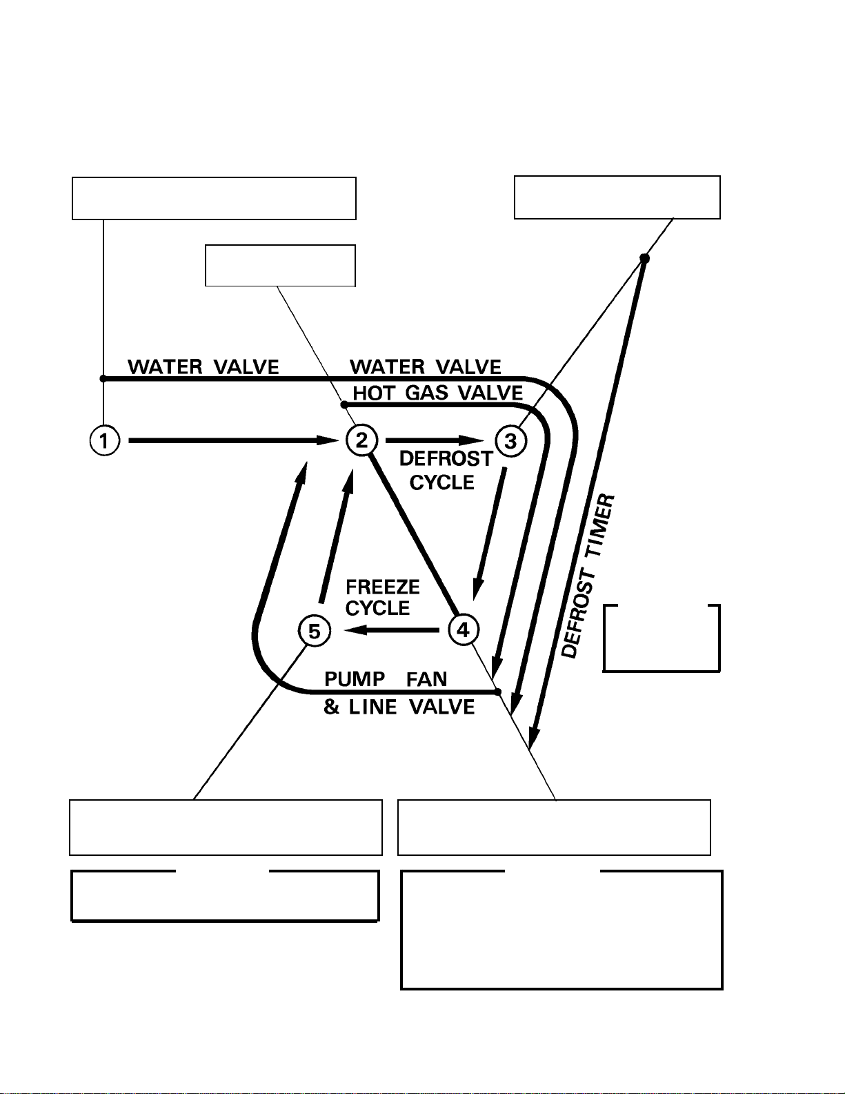
[c] SEQUENCE
1st Cycle
1. Unit energized and Control Switch to “ICE”
position. Water supply cycle starts.
2. After 1 minute,
Defrost cycle starts.
3. Thermistor reads 48° F.
Defrost Timer starts counting.
IMPORTANT
Water Valve
opening is limited
to 6 minutes.
&
5. After the first 5 minutes in freeze cycle.
Ready to complete freeze cycle when Float
Switch circuit opens.
4. Defrost Timer stops counting.
Defrost cycle is completed and freeze cycle
starts.
IMPORTANT
Board never accepts freeze completion signal
within the first 5 minutes in freeze cycle.
IMPORTANT
1. Board never accepts defrost completion
signal within the first 2 minutes in defrost
cycle.
2. Defrost cycle time is limited to 20 minutes
even if Defrost Timer does not stop counting.
19
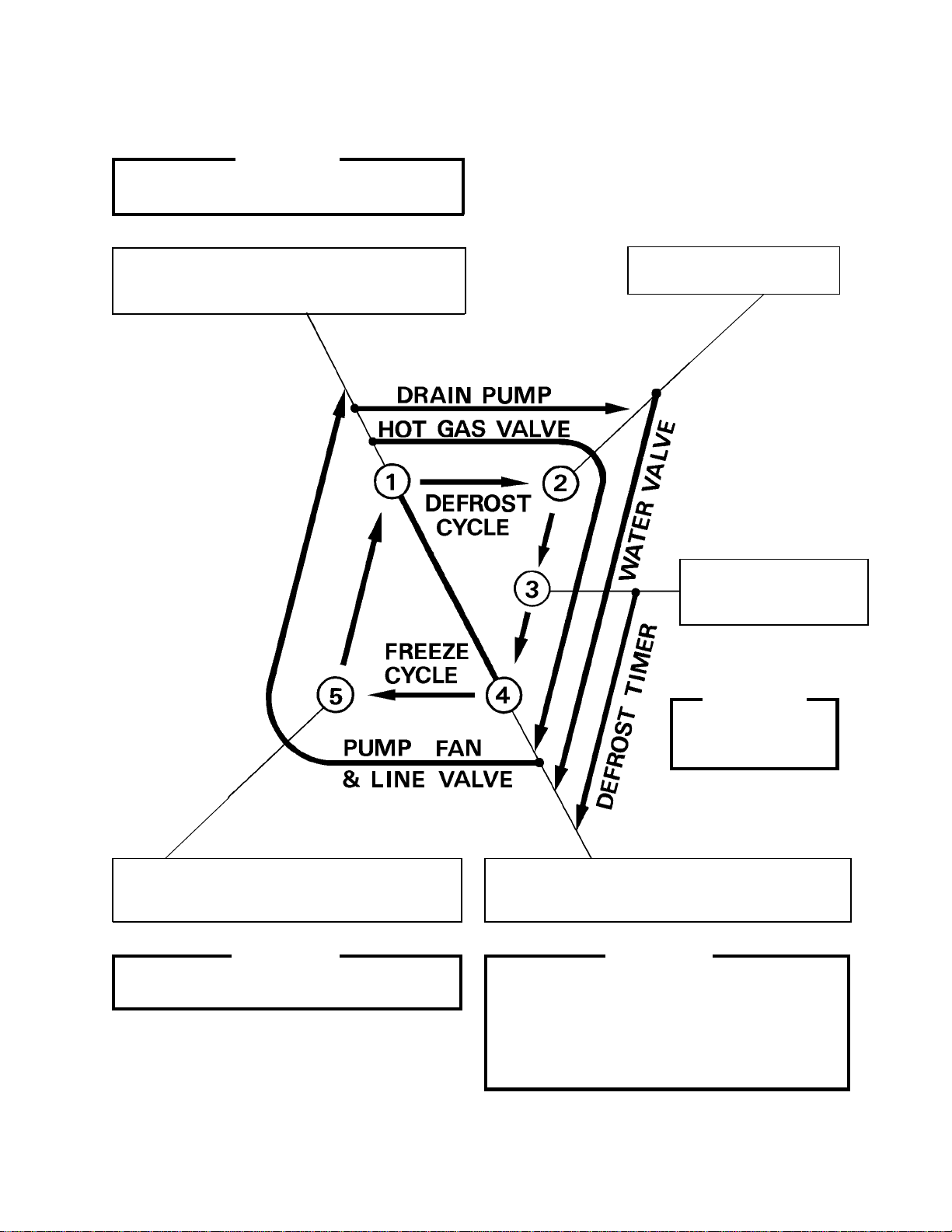
2nd Cycle and after with pump drain
IMPORTANT
Freeze cycle time is limited to 60 minutes even
if Float Switch does not open.
1. Float Switch opens and signals to complete
freeze cycle.
Drain timer starts counting.
2. Drain timer stops counting.
Pump drain is completed
3. Thermistor reads 48° F.
Defrost Timer starts
counting.
IMPORTANT
Water Valve
opening is limited to 6
minutes.
5. After the first 5 minutes in freeze cycle.
Ready to complete freeze cycle when Float
Switch circuit opens.
4. Defrost Timer stops counting.
Defrost cycle is completed and freeze cycle
starts.
IMPORTANT
Board never accepts freeze completion signal
within the first 5 minutes in freeze cycle.
IMPORTANT
1. Board never accepts defrost completion
signal within the first 2 minutes in defrost
cycle.
2. Defrost cycle time is limited to 20 minutes
even if Defrost Timer does not stop counting.
&
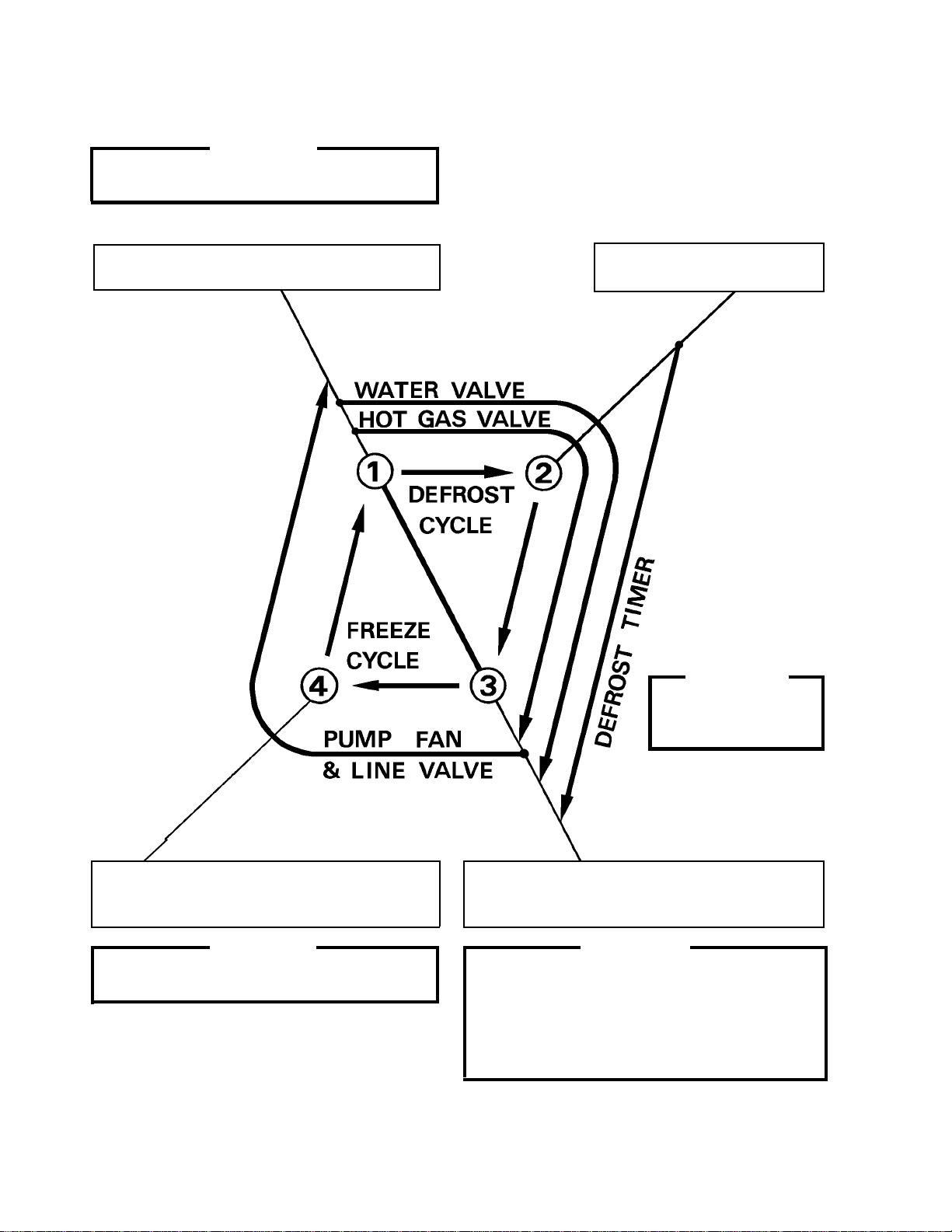
20
IMPORTANT
Freeze cycle time is limited to 60 minutes even
if Float Switch does not open.
2nd Cycle and after with no pump drain
1. Float Switch opens and signals to complete
freeze cycle.
2. Thermistor reads 48° F.
Defrost Timer starts counting.
IMPORTANT
Water Valve
opening is limited to 6
minutes.
4. After the first 5 minutes in freeze cycle.
Ready to complete freeze cycle when Float
Switch circuit opens.
3. Defrost Timer stops counting.
Defrost cycle is completed and freeze cycle
starts.
IMPORTANT
Board never accepts freeze completion signal
within the first 5 minutes in freeze cycle.
IMPORTANT
1. Board never accepts defrost completion
signal within the first 2 minutes in defrost
cycle.
2. Defrost cycle time is limited to 20 minutes
even if Defrost Timer does not stop counting.
&
21
[d] CONTROLS AND ADJUSTMENTS
The Dip Switch is factory-adjusted to the following positions:
FOR MODELS WITH MECHANICAL BIN CONTROL:
Switch Nos. 1 and 2:
Used for adjustment of the Defrost Timer.
The Defrost Timer starts counting when the Thermistor reads a certain temperature
at the Evaporator outlet.
Switch Nos. 3 and 4:
Used for adjustment of the Drain Timer.
When a freeze cycle is completed, the Pump Motor stops, and the icemaker
resumes operation in 2 seconds. Then the Pump Motor drains the Water Tank
for the time determined by the Drain Timer. The Drain Timer also determines the
time to restrain completion of a defrost cycle, i.e. the minimum defrost time.
Switch Nos. 5 and 6:
Used for adjustment of the Drain Counter.
The Pump Motor drains the Water Tank at the frequency determined by the Drain
Counter.
Switch No. 7:
Used only on models with mechanical bin control. Dip Switch should be set “ON”.
(Models with bin thermostat, Switch No. 7 should be set in the “OFF” position.)
Switch No. 8:
Used only for checking the Controller Board. Usually set in OFF position.
FOR MODELS WITH THERMOSTAT :
DIP SWITCH NO. 1 2 3 4 5 6 7 8 9 10
KM-630MAH OFF OFF OFF OFF ON ON ON OFF ON OFF
KM-630MWH OFF OFF OFF OFF ON ON ON OFF OFF OFF
KM-630MRH OFF OFF OFF OFF ON ON ON OFF ON OFF
DIP SWITCH NO. 1 2 3 4 5 6 7 8 9 10
KM-630MAH OFF OFF OFF OFF ON ON OFF OFF ON OFF
KM-630MWH OFF OFF OFF OFF ON ON OFF OFF OFF OFF
KM-630MRH OFF OFF OFF OFF ON ON OFF OFF ON OFF
Loading...