


 Loading...
Hoshizaki F1002MAJ, F801MWJC, F1002MRJC, F1002MWJC, F1002MAJC User Manual
...Service Manual
Modular Flaker with
F-A and F-C Control Boards
Models
H and J Series
Number: 73204
hoshizakiamerica.com Issued: 7-23-2014
Revised: 6-8-2018
 WARNING
Only qualified service technicians should install and service the appliance. To obtain the name and phone number of your local Hoshizaki Certified Service
Representative, visit www.hoshizaki.com. No service should be undertaken until the technician has thoroughly read this Service Manual. Failure to service and maintain the appliance in accordance with this manual will adversely affect safety, performance, component life, and warranty coverage and may result in costly water damage. Proper installation is the responsibility of the installer. Product failure or property damage due to improper installation is not covered under warranty.
Hoshizaki provides this manual primarily to assist qualified service technicians in the service of the appliance.
Should the reader have any questions or concerns which have not been satisfactorily addressed, please call, send an e-mail message, or write to the Hoshizaki Technical Support Department for assistance.
Phone: 1-800-233-1940; (770) 487-2331
Fax: 1-800-843-1056; (770) 487-3360
E-mail: techsupport@hoshizaki.com
618 Highway 74 South
Peachtree City, GA 30269
Attn: Hoshizaki Technical Support Department
Web Site: www.hoshizaki.com
NOTE: To expedite assistance, all correspondence/communication MUST include the following information:
•Model Number
•Serial Number
•Complete and detailed explanation of the problem.
2
IMPORTANT |
|
This manual should be read carefully before the appliance is serviced. Read |
|
the warnings and guidelines contained in this manual carefully as they provide |
|
essential information for the continued safe use, service, and maintenance of the |
|
appliance. Retain this manual for any further reference that may be necessary. |
|
CONTENTS |
|
Important Safety Information.................................................................................................. |
6 |
I. Construction and Water/Refrigeration Circuit Diagram........................................................ |
8 |
A. Construction................................................................................................................... |
8 |
1. Air-Cooled Models..................................................................................................... |
8 |
2. Water-Cooled Models .............................................................................................. |
9 |
3. Remote Air-Cooled Models..................................................................................... |
10 |
4. Low-Side, Parallel Rack System Models................................................................. |
11 |
B. Icemaking Unit............................................................................................................. |
12 |
C. Water/Refrigeration Circuit Diagram............................................................................ |
13 |
1. Air-Cooled Models................................................................................................... |
13 |
2. Water-Cooled Models............................................................................................. |
14 |
3. Remote Air-Cooled Models..................................................................................... |
15 |
4. Low-Side, Parallel Rack System Models................................................................ |
16 |
II. Sequence of Operation and Service Diagnosis................................................................ |
17 |
A. Sequence of Operation Flow Chart............................................................................. |
17 |
1. Icemaking and Drain Cycle..................................................................................... |
17 |
2. Shutdown............................................................................................................... |
18 |
B. Service Diagnosis........................................................................................................ |
19 |
C. Control Board Check.................................................................................................... |
25 |
D. Bin Control Check........................................................................................................ |
30 |
E. Float Switch Check and Cleaning................................................................................ |
34 |
F. Diagnostic Tables.......................................................................................................... |
36 |
III. Controls and Adjustments................................................................................................ |
39 |
A. Control Board............................................................................................................... |
39 |
1. Control Board Layout.............................................................................................. |
40 |
2. LED Lights and Audible Alarm Safeties.................................................................. |
41 |
3. Ice Purge Cycle Bypass......................................................................................... |
42 |
B. Controls and Adjustments............................................................................................ |
42 |
1. Default Dip Switch Settings..................................................................................... |
42 |
2. BC1 (Infrared Sensor) Shutdown Delay (S1 dip switch 1, 2, 3).............................. |
43 |
3. Drain Frequency Control (S1 dip switch 4)............................................................. |
43 |
4. Continuous Dispensing Timer (S1 dip switch 5 & 6).............................................. |
43 |
5. Bin Control Selector (S1 dip switch 7).................................................................... |
44 |
6. BC(2) (Mech. Stand-Alone or Backup (only)) Shutdown Delay (S1 dip switch 8).. |
44 |
7. Factory Use (S1 Dip Switch 9 & 10)........................................................................ |
44 |
C. Power Switch and Control Switch................................................................................ |
45 |
IV. Refrigeration Circuit and Component Service Information.............................................. |
46 |
A. Refrigeration Circuit Service Information..................................................................... |
46 |
B. Component Service Information.................................................................................. |
49 |
3
V. Maintenance..................................................................................................................... |
56 |
VI. Disposal.......................................................................................................................... |
58 |
VII. Technical Information..................................................................................................... |
59 |
A. Specification & Performance Data Sheets................................................................... |
59 |
1a. F-1001MAH.......................................................................................................... |
59 |
1b. F-1001MAH-C....................................................................................................... |
60 |
2a. F-1001MWH......................................................................................................... |
61 |
2b. F-1001MWH-C...................................................................................................... |
62 |
3a. F-1001MRH.......................................................................................................... |
63 |
3b. F-1001MRH-C....................................................................................................... |
64 |
4a. F-1501MAH.......................................................................................................... |
65 |
4b. F-1501MAH-C ...................................................................................................... |
66 |
5a. F-1501MWH......................................................................................................... |
67 |
5b. F-1501MWH-C...................................................................................................... |
68 |
6a. F-1501MRH.......................................................................................................... |
69 |
6b. F-1501MRH-C...................................................................................................... |
70 |
7. F-2001MWH............................................................................................................ |
71 |
8a. F-2001MRH.......................................................................................................... |
72 |
8b. F-2001MRH-C...................................................................................................... |
73 |
8c. F-2001MRH3......................................................................................................... |
74 |
9. F-2001MLH............................................................................................................. |
75 |
10. FD-650MAH-C...................................................................................................... |
76 |
11. FD-650MWH-C..................................................................................................... |
77 |
12. FD-650MRH-C..................................................................................................... |
78 |
13. FD-1001MAH-C.................................................................................................... |
79 |
14. FD-1001MRH-C.................................................................................................... |
80 |
15a. F-450MAJ........................................................................................................... |
81 |
15b. F-450MAJ-C....................................................................................................... |
82 |
16a. F-801MAJ........................................................................................................... |
83 |
16b. F-801MAJ-C....................................................................................................... |
84 |
17a. F-801MWJ.......................................................................................................... |
85 |
17b. F-801MWJ-C...................................................................................................... |
86 |
18a. F-1001MAJ......................................................................................................... |
87 |
18b. F-1001MAJ-C...................................................................................................... |
88 |
19a. F-1001MWJ........................................................................................................ |
89 |
19b. F-1001MWJ-C..................................................................................................... |
90 |
20a. F-1001MRJ......................................................................................................... |
91 |
20b. F-1001MRJ-C..................................................................................................... |
92 |
21a. F-1001MLJ.......................................................................................................... |
93 |
21b. F-1002MLJ......................................................................................................... |
94 |
22a. F-1002MAJ......................................................................................................... |
95 |
22b. F-1002MAJ-C..................................................................................................... |
96 |
23a. F-1002MWJ........................................................................................................ |
97 |
23b. F-1002MWJ-C.................................................................................................... |
98 |
24a. F-1002MRJ......................................................................................................... |
99 |
24b. F-1002MRJ-C................................................................................................... |
100 |
4
25a. F-1501MAJ........................................................................................................ |
101 |
25b. F-1501MAJ-C................................................................................................... |
102 |
26a. F-1501MWJ...................................................................................................... |
103 |
26b. F-1501MWJ-C.................................................................................................. |
104 |
27a. F-1501MRJ....................................................................................................... |
105 |
27b. F-1501MRJ-C................................................................................................... |
106 |
28a. F-2001MLJ....................................................................................................... |
107 |
28b. F-2001MWJ...................................................................................................... |
108 |
28c. F-2001MRJ....................................................................................................... |
109 |
28d. F-2001MRJ-C.................................................................................................... |
110 |
28e. F-2001MRJ3...................................................................................................... |
111 |
29. FD-1001MAJ-C.................................................................................................... |
112 |
30. FD-1001MRJ-C................................................................................................... |
113 |
31. FD-1002MAJ-C.................................................................................................... |
114 |
32. FD-1002MRJ-C................................................................................................... |
115 |
B. Wiring Diagrams......................................................................................................... |
116 |
1. F-1001MAH(-C), F-1001MWH(-C), F-1001MRH(-C), FD-1001M_H-C.................... |
116 |
2. F-1501M_H(-C)...................................................................................................... |
117 |
3. F-2001MWH(-C), F-2001MRH(-C)(3),F-2001MWJ, F-2001MRJ(-C)(3)................. |
118 |
4. F-2001MLH, F-1001MLJ, F-1002MLJ, F-2001MLJ................................................. |
119 |
5. FD-650M_H-C...................................................................................................... |
120 |
6. F-450MAJ(-C)....................................................................................................... |
121 |
7. F-801M_J(-C)........................................................................................................ |
122 |
8. F-1001MAJ(-C), F-1001MWJ(-C), F-1001MRJ(-C)............................................... |
123 |
9. F-1002MAJ(-C), F-1002MWJ(-C), F-1002MRJ(-C), FD-1002M_J-C.................... |
124 |
10. F-1501M_J(-C).................................................................................................... |
125 |
11. FD-1001M_J-C.................................................................................................... |
126 |
5

Important Safety Information
Throughout this manual, notices appear to bring your attention to situations which could result in death, serious injury, damage to the appliance, or damage to property.
WARNING |
Indicates a hazardous situation which could result in death or |
|
serious injury. |
NOTICE |
Indicates a situation which could result in damage to the |
|
appliance or property. |
IMPORTANT |
Indicates important information about the installation, use, and |
|
care of the appliance. |
 WARNING
The appliance should be destined only to the use for which it has been expressly conceived. Any other use should be considered improper and therefore dangerous. The manufacturer cannot be held responsible for injury or damage resulting
from improper, incorrect, and unreasonable use. Failure to install, operate, and maintain the appliance in accordance with this manual will adversely affect safety, performance, component life, and warranty coverage and may result in costly water damage.
To reduce the risk of death, electric shock, serious injury, or fire, follow basic precautions including the following:
•Only qualified service technicians should install and service the appliance.
•The appliance must be installed in accordance with applicable national, state, and local codes and regulations.
•Electrical connection must be hard-wired and must meet national, state, and local electrical code requirements. Failure to meet these code requirements could result in death, electric shock, serious injury, fire, or damage.
•The icemaker requires an independent power supply of proper capacity. See the nameplate for electrical specifications. Failure to use an independent power supply
of proper capacity can result in a tripped breaker, blown fuse, damage to existing wiring, or component failure. This could lead to heat generation or fire.
•THE ICEMAKER MUST BE GROUNDED. Failure to properly ground the icemaker could result in death or serious injury.
•To reduce the risk of electric shock, do not touch the power switch or control switch with damp hands.
•Move the power switch to the "OFF" position and turn off the power supply before servicing. Lockout/Tagout to prevent the power supply from being turned back on inadvertently.
•Do not place fingers or any other objects into the ice discharge opening.
•Do not make any alterations to the appliance. Alterations could result in electric shock, injury, fire, or damage.
6

 WARNING, continued
•The appliance is not intended for use by persons (including children) with reduced physical, sensory, or mental capabilities, or lack of experience and knowledge, unless they have been given supervision or instruction concerning use of the appliance by a person responsible for their safety.
•Children should be properly supervised around the appliance.
•Do not climb, stand, or hang on the appliance or allow children or animals to do so. Serious injury could occur or the appliance could be damaged.
•Do not use combustible spray or place volatile or flammable substances near the appliance. They might catch fire.
•Keep the area around the appliance clean. Dirt, dust, or insects in the appliance could cause harm to individuals or damage to the appliance.
Additional Warning for Remote Models
•THE REMOTE CONDENSER UNIT MUST BE GROUNDED. The power supply and ground connection to the remote condenser unit are supplied from the icemaker.
Failure to properly ground the remote condenser unit could result in death or serious injury.
•Wire routing (conduit) and disconnect (if required) must meet national, state, and local electrical code requirements. Failure to meet these code requirements could result in death, electric shock, serious injury, fire, or damage.
NOTICE
•Follow the instructions in this manual carefully to reduce the risk of costly water damage.
•In areas where water damage is a concern, install in a contained area with a floor drain.
•Install the appliance in a location that stays above freezing. Normal operating ambient temperature must be within 45°F to 100°F (7°C to 38°C).
•Do not leave the icemaker on during extended periods of non-use, extended absences, or in sub-freezing temperatures. To properly prepare the icemaker for these occasions, follow the instructions provided in the instruction manual.
•Do not place objects on top of the appliance.
•The dispenser unit/ice storage bin is for ice use only. Do not store anything else in the dispenser unit/ice storage bin.
7
I. Construction and Water/Refrigeration Circuit Diagram
A. Construction
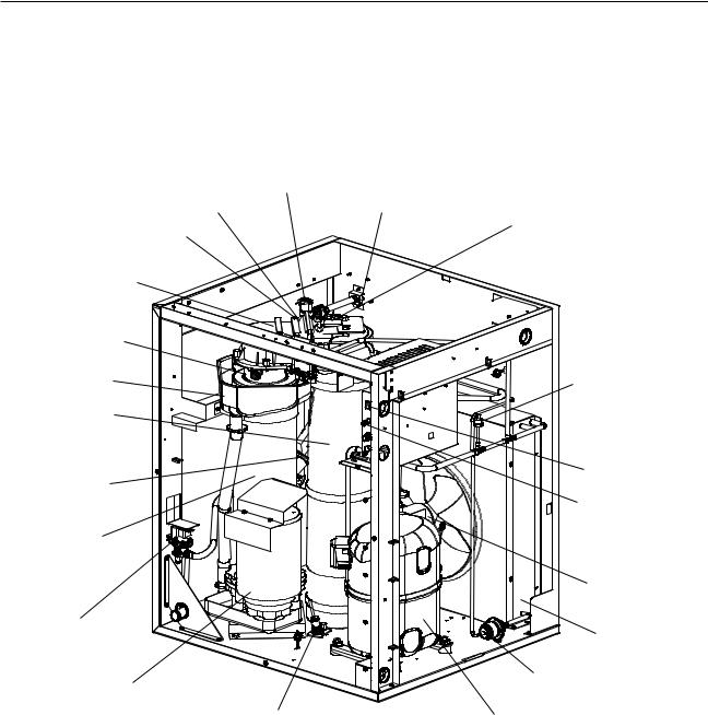
1. Air-Cooled Models
Inlet Water Valve
Float Switch
Reservoir
Spout
Evaporator
Heater (-C)
Drip Pan
Ice Chute
Thermostatic
Expansion Valve
Evaporator
Drain Valve
Gear Motor
Water Supply Inlet
Bin Control 2 (Mechanical) (If Applicable)


 Junction Box
High-Pressure Switch
Control Switch
Power Switch
Fan Motor
Condenser
|
Drier |
Bin Control 1 |
Compressor |
(Infrared Sensor) |
|
Model Shown: F-1501MAH |
|
8
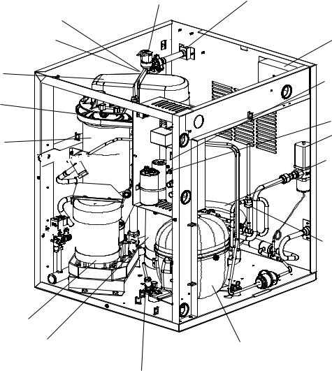
2. Water-Cooled Models
Inlet Water Valve
Float Switch
Reservoir
Spout
Drip Pan
Evaporator
Thermostatic 


Expansion Valve
Drain Valve 


Gear Motor
Ice Chute
Bin Control 1
(Infrared Sensor)
Water Supply Inlet
Junction Box
Control Switch
Power Switch
Water Regulating
Valve
Water-Cooled
Condenser
High-Pressure Switch
 Drier
Drier
Compressor
Model Shown: FD-650MWH-C
9

3. Remote Air-Cooled Models
Bin Control 2 (Mechanical) (If Applicable)
Inlet Water Valve |
Water Supply Inlet |
|
|
|
Float Switch |
|
|
|
|
|
|
|
|
|
|
|
High-Pressure Switch |
||
Reservoir |
|
|
|
|
Spout |
|
|
|
|
|
|
|
|
Junction Box |
Drip Pan |
|
|
|
|
Evaporator |
|
|
|
|
Heater (-C) |
|
|
|
|
Evaporator |
|
|
Control Switch |
|
|
|
|
|
|
|
|
|
Power Switch |
|
Thermostatic |
|
|
Reciever |
|
Expansion Valve |
|
|
||
|
|
|
|
|
Drain Valve |
|
|
|
Drier |
Gear Motor |
|
Compressor |
||
Ice Chute |
|
Crankcase |
|
|
|
|
Heater |
|
|
Model Shown: F-1001MRH-C |
|
|
||
Junction Box |
|
|
|
|
|
High-Pressure Switch |
|
|
|
Inlet Water Valve |
|
|
|
|
Reservoir |
|
|
Evaporator |
|
Spout |
|
|
||
|
|
Heater (-C) |
||
|
|
|
||
Water Supply Inlet |
|
|
|
Control Switch |
Float Switch |
|
|
|
Power Switch |
|
|
|
|
|
Drip Pan |
|
|
|
|
|
|
|
|
Ice Chute |
Reciever |
|
|
|
Drier |
|
|
|
|
|
Evaporator |
|
|
|
|
|
|
|
|
Compressor |
Bin Control |
|
|
Thermostatic |
|
|
|
Expansion Valve |
||
(Infrared Sensor) |
|
|
||
|
|
|
|
|
Drain Valve |
|
Gear Motor |
Crankcase |
|
Model Shown: F-1001MRJ-C |
Heater |
|
10
4. Low-Side, Parallel Rack System Models
Inlet Water Valve
Float Switch
Reservoir
Spout
Evaporator 
Heater (-C)
Evaporator
Thermostatic 


Expansion Valve
Drain Valve 


Gear Motor
Ice Chute
Bin Control 1 (infrared sensor)
Bin Control 2 (Mechanical) (If Applicable)
Water Supply Inlet
Control Switch


 Liquid Line Valve
|
Suction Line Valve |
Power Switch |
Evaporator Pressure |
|
Regulator Valve (EPR) |
Model Shown: F-2001MLH
11
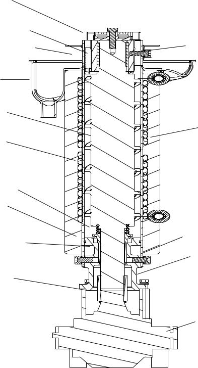
B. Icemaking Unit
Cutter |
|
Extruding Head-Upper Bearing |
|
Evaporator Heater (-C Models) |
Seal Bolt |
|
|
Drip Pan |
|
Auger |
|
|
Insulation |
Cylinder |
|
Mechanical-Seal |
|
O-Ring |
|
|
Socket Head Cap Screw |
Lower Housing |
with Split Lock Washer |
|
|
|
Hex Bolt and Washer |
Spline Coupling |
|
|
Gear Motor |
|
Model Shown: F-1501MAH |
12

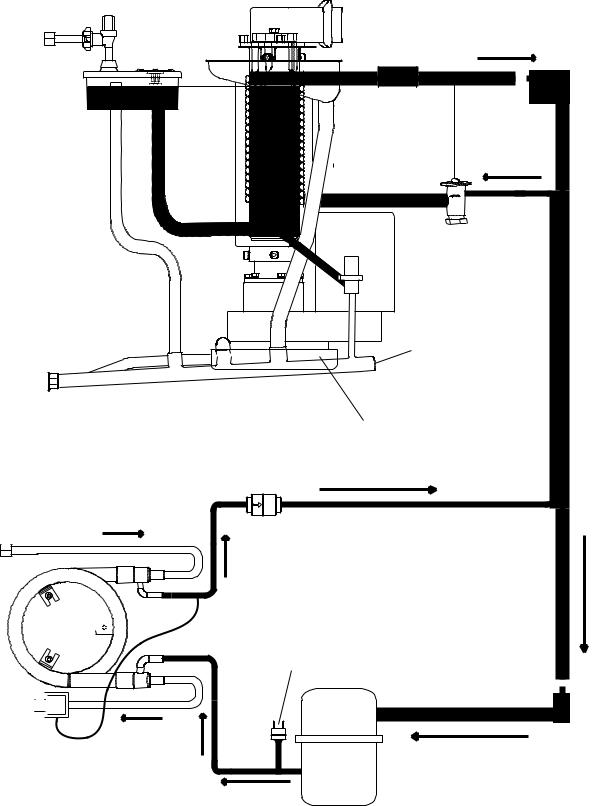
C. Water/Refrigeration Circuit Diagram
1. Air-Cooled Models
Inlet Water Valve
Water Supply |
Float |
Switch |
|
Line |
|
Reservoir |
|
|
Water Level |
|
Evaporator |
Overflow |
|
|
|
|
|
|
|
|
|
|
Spout |
|
Evaporator Condensate |
||||||||||
|
|
|
|
|
|
|
|
|
|
|
|||||||||||
|
|
|
|
|
|
|
|
|
|
|
Drain Pan (Drip Pan) |
||||||||||
|
|
|
|
|
|
|
|
|
|
||||||||||||
|
|
|
|
|
|
|
|
|
|
||||||||||||
|
|
|
|
|
|
|
|
|
|
|
|
|
|
|
|
|
|
|
|
|
|
|
|
|
|
|
|
|
|
|
|
|
|
|
|
|
|
|
|
|
|
|
|
|
|
|
|
|
|
|
|
|
|
|
|
|
|
|
|
|
|
|
|
|
|
|
|
|
|
|
|
|
|
|
|
|
|
|
|
|
|
|
|
|
|
|
|
|
|
|
|
|
|
|
|
|
|
|
|
|
|
|
|
|
|
|
|
|
|
|
|
|
|
|
|
|
|
|
|
|
|
|
|
|
|
|
|
|
|
|
|
|
|
|
|
|
|
|
|
|
|
|
|
|
|
|
|
Insulation |
|||||
|
|
|
|
|
|
|
|
|
|
|
|
|
|
|
|
|
|
|
|
|
|
|
|
|
|
|
|
|
|
|
|
|
|
|
|
|
|
|
|
|
|
|
|
|
|
|
|
|
|
|
|
|
|
|
|
|
|
|
|
|
|
|
|
|
|
|
|
|
|
|
|
|
|
|
|
|
|
|
|
|
|
|
|
|
|
|
|
|
|
|
|
|
|
|
|
|
|
|
|
|
|
|
|
|
|
|
|
|
|
|
|
|
|
|
|
|
|
|
|
|
|
|
|
|
|
|
|
|
|
|
|
|
|
|
|
|
|
|
|
|
|
|
|
|
|
|
|
|
|
|
|
|
|
|
|
|
|
|
|
|
|
|
|
|
|
|
|
|
|
|
|
|
|
|
|
|
|
|
|
|
|
|
|
|
|
|
|
|
|
|
|
|
|
|
|
|
|
|
|
|
|
|
|
|
|
|
|
|
|
|
|
|
|
|
|
|
|
|
|
Drain |
Thermostatic |
Valve |
Expansion Valve |
Gear Motor
|
Drain Hose |
Drain Outlet |
Gear Motor Drain Pan |
|
Condenser
Fan Motor


 Drier
Drier
Condenser
High Pressure
Switch
Compressor
13
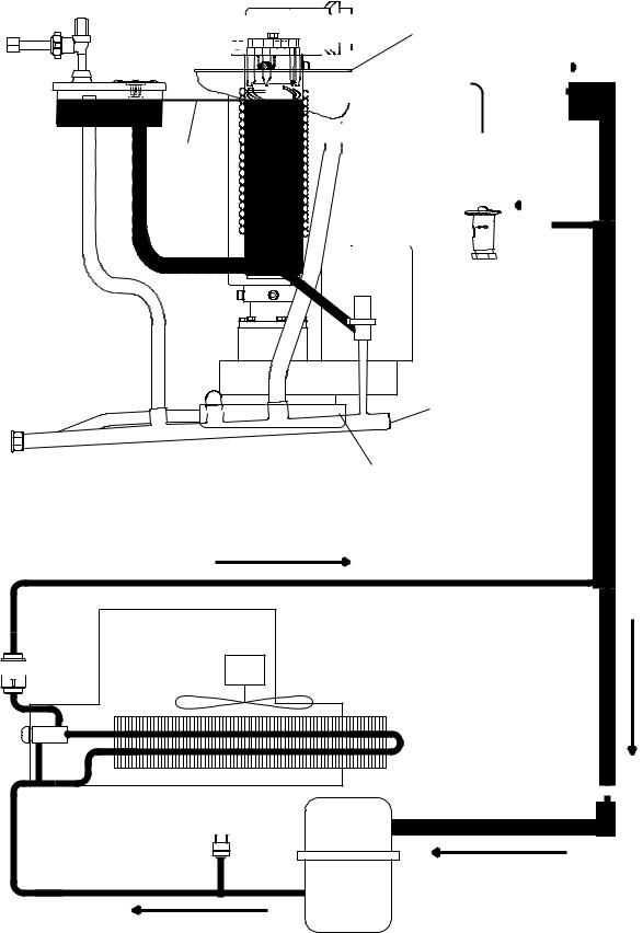
2. Water-Cooled Models
|
Inlet Water Valve |
Spout |
|
Water Supply |
|
Evaporator Condensate |
|
Float |
Drain Pan (Drip Pan) |
||
Line |
|||
Switch |
|
||
|
|
Reservoir |
|
Insulation |
|
|
|
|
Water Level |
|
|
Evaporator |
|
Overflow |
|
|
|
Drain |
Thermostatic |
|
Valve |
|
|
Expansion Valve |
|
|
|
|
|
|
Gear Motor |
|
|
Drain Hose |
Drain Outlet
Gear Motor Drain Pan
Drier
Water Supply Line
Condenser 


High-Pressure
Switch
Drain Outlet 

Water Regulating Valve
Compressor
14
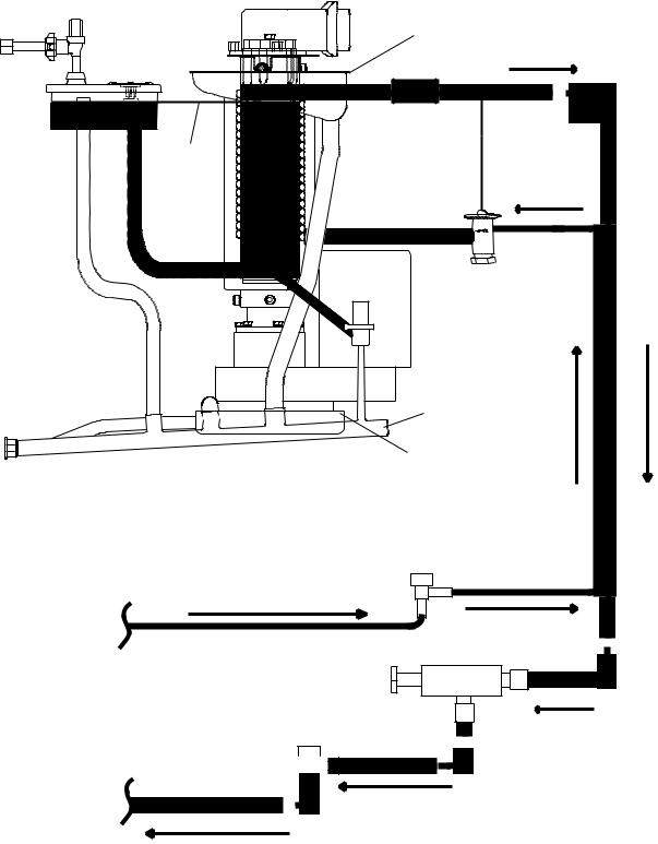
3. Remote Air-Cooled Models
Inlet Water Valve
Water Supply |
Float |
Switch |
|
Line |
|
Reservoir |
|
|
Water Level |
|
Evaporator |
Overflow |
|
|
|
|
|
|
|
|
|
|
|
|
|
|
Spout |
|
Evaporator Condensate |
||||||||||
|
|
|
|
|
|
|
|
|
|
|
|
|
|
|
|||||||||||
|
|
|
|
|
|
|
|
|
|
|
|
|
|
|
Drain Pan (Drip Pan) |
||||||||||
|
|
|
|
|
|
|
|
|
|
|
|
|
|
||||||||||||
|
|
|
|
|
|
|
|
|
|
|
|
|
|
|
|
|
|
|
|
|
|
|
|
|
|
|
|
|
|
|
|
|
|
|
|
|
|
|
|
|
|
|
|
|
|
|
|
|
|
|
|
|
|
|
|
|
|
|
|
|
|
|
|
|
|
|
|
|
|
|
|
|
|
|
|
|
|
|
|
|
|
|
|
|
|
|
|
|
|
|
|
|
|
|
|
|
|
|
|
|
|
|
|
|
|
|
|
|
|
|
|
|
|
|
|
|
|
|
|
|
|
|
|
|
|
|
|
|
|
|
|
|
|
|
|
|
|
|
|
|
|
|
|
|
|
|
|
|
|
|
|
|
|
|
|
|
|
|
|
|
|
|
|
|
|
|
|
|
|
|
|
|
|
|
|
Insulation |
|||||
|
|
|
|
|
|
|
|
|
|
|
|
|
|
|
|
|
|
|
|
|
|
|
|
|
|
|
|
|
|
|
|
|
|
|
|
|
|
|
|
|
|
|
|
|
|
|
|
|
|
|
|
|
|
|
|
|
|
|
|
|
|
|
|
|
|
|
|
|
|
|
|
|
|
|
|
|
|
|
|
|
|
|
|
|
|
|
|
|
|
|
|
|
|
|
|
|
|
|
|
|
|
|
|
|
|
|
|
|
|
|
|
|
|
|
|
|
|
|
|
|
|
|
|
|
|
|
|
|
|
|
|
|
|
|
|
|
|
|
|
|
|
|
|
|
|
|
|
|
|
|
|
|
|
|
|
|
|
|
|
|
|
|
|
|
|
|
|
|
|
|
|
|
|
|
|
|
|
|
|
|
|
|
|
|
|
|
|
|
|
|
|
|
|
|
|
|
|
|
|
|
|
|
|
|
|
|
|
|
|
|
|
|
|
|
|
|
|
|
|
|
|
|
|
|
|
|
|
|
|
|
|
|
|
Drain |
Thermostatic |
Valve |
Expansion Valve |
Gear Motor
|
Drain Hose |
Drain Outlet |
Gear Motor Drain Pan |
|
Condenser Fan Motor


 Drier
Drier
Remote Condenser |
High-Pressure
Switch
Compressor
15
4. Low-Side, Parallel Rack System Models
Inlet Water Valve |
|
|
|
Spout |
Evaporator Condensate |
|
|
|
Water Supply |
Float |
Drain Pan (Drip Pan) |
Switch |
|
|
Line |
|
|
|
|
|
Reservoir |
|
Insulation |
|
|
|
|
Water Level |
|
|
Evaporator |
|
Overflow |
|
|
|
Drain |
Thermostatic |
|
Valve |
Expansion Valve |
|
|
Gear Motor |
Drain Outlet |
Drain Hose |
|
|
NOTICE! F-1001MLH Use only with R-404A |
Gear Motor Drain Pan |
|
|
F-1002MLJ Use only with R-404A, R-407A, or R-407F |
|
EPR Settings: |
|
F-1001MLH: R-404A EPR Setting: 31 PSIG |
|
F-1002MLJ: R-404A EPR Setting: 31 PSIG |
Liquid Line Valve |
R-407A EPR Setting: 22 PSIG |
|
R-407F EPR Setting: 23 PSIG |
|
From Rack System |
|
|
Evaporator Pressure Regulator (EPR Valve) |
Suction Line Valve
To Rack System
16
|
|
|
|
|
|
|
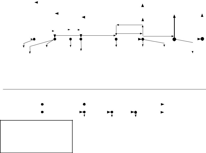
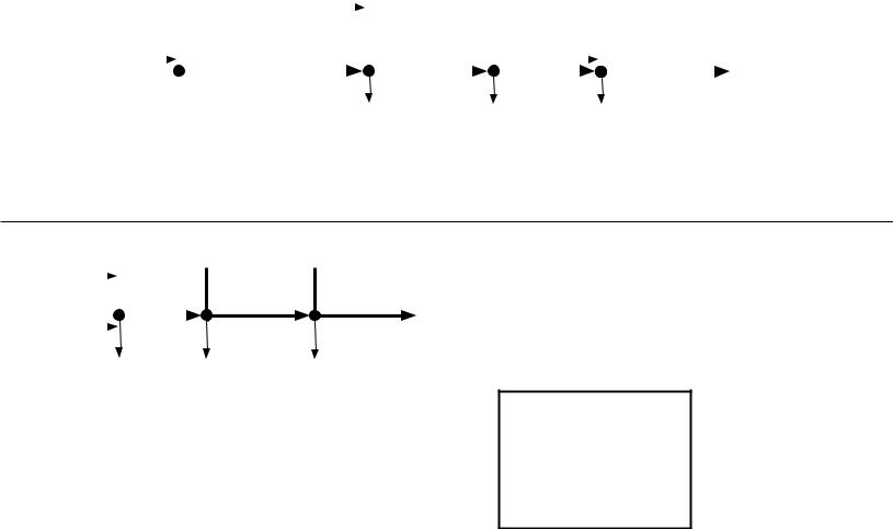
Control Board Sequence of Operation Flow Chart - Icemaking and Drain Cycle |
|
|
|
|
|
||||||||||||||||||||||||||||
|
|
|
|
|
|
|
|
|
|
4. 1-in-12 Drain Cycle - Although the factory default 1-in-1 drain cycle |
|
|
|
|
|
|
|
|
|
|
|
|
.1 |
|||||||||||||||||
|
|
|
|
|
|
|
|
|
|
|
|
|
|
|
|
|
|
|
|
|
|
Icemaking |
||||||||||||||||||
|
|
|
|
|
|
|
|
|
|
is recommended, a 1-in-12 drain cycle is available. For 1-in-12 drain |
|
|
|
|
|
|
|
|
|
|
|
|||||||||||||||||||
|
|
|
|
|
|
|
|
|
|
cycle sequence, see "3. 1-in-12 Hour Drain Cycle & Restart (optional)." |
|
|
|
|
|
|
|
|
|
|
|
|||||||||||||||||||
|
1. Startup |
|
|
|
|
|
|
|
|
|
|
|
|
|
|
|
|
|
|
|
|
|
|
|
|
|
|
|
|
|
|
|
|
|
|
|
|
|||
|
|
|
|
|
|
|
|
|
|
|
|
|
|
|
|
|
|
|
|
|
|
|
|
|
|
|
|
|
|
|
|
|
|
|
|
|
||||
|
|
1. Fill Cycle |
|
|
|
|
|
|
|
|
|
|
|
|
|
|
|
|
|
|
|
|
|
|
Low Water Safety |
Low Water Safety |
|
|||||||||||||
|
|
|
|
|
|
|
|
|
|
|
|
|
|
|
|
|
|
|
|
|
|
|
|
|
||||||||||||||||
|
Power Switch "ON" |
|
|
2. Ice Purge Cycle |
|
3. Freeze Cycle |
|
|
|
|
|
|
|
|
Purge Timer |
|
|
|
Shutdown |
|
|
|
|
|||||||||||||||||
|
|
|
|
|
|
|
|
|
|
|
|
|
|
|
|
|
|
|||||||||||||||||||||||
|
Control Switch in "ICE" |
|
|
|
|
|
|
To bypass, press the |
|
1-in-1 drain cycle. DV opens for 2 sec. every hour |
|
|
|
|
|
|
|
|
|
|
||||||||||||||||||||
|
|
|
|
|
|
|
|
|
|
90 sec. FT exceeded, |
90. sec. PT terminates |
|
and |
|||||||||||||||||||||||||||
|
POWER OK LED on |
|
|
|
|
|
|
"SERVICE" button after |
|
(CB S1 Dip Switch 4). |
|
Refill |
|
|
|
|||||||||||||||||||||||||
|
|
|
|
|
|
|
GM starts. |
|
|
|
|
90 sec. PT starts and |
unit shuts down and |
|
||||||||||||||||||||||||||
|
BC1 Green LED on |
|
|
|
|
|
|
|
Icemaker status does not change. |
FT Maximum |
|
|
1-beep alarm continues. |
|
||||||||||||||||||||||||||
|
|
|
|
|
|
|
|
|
|
|
|
|
|
|
|
|
|
|
|
|
|
|
1-beep alarm sounds |
|
|
|||||||||||||||
|
BC1 Yellow LED off |
|
|
|
|
|
5 or 30 sec. |
5 min. |
|
|
|
|
|
|
|
90 sec. |
|
|
When UFS closes, alarm |
|
Drain |
|||||||||||||||||||
|
|
FT Maximum |
|
|
|
|
|
|
|
|
|
|||||||||||||||||||||||||||||
|
|
(S1 Dip Switch 7) |
|
|
|
|
|
|
|
|
|
90 sec. |
|
|
|
|
||||||||||||||||||||||||
|
BC(2) Closed |
|
|
|
|
|
|
|
|
|
|
|
|
|
resets and 2. Ice Purge |
|
||||||||||||||||||||||||
|
Startup |
|
|
|
90 sec. |
|
|
|
|
|
|
|
|
|
|
|
30-min. FZT |
|
|
|
|
|
|
|
|
|
|
|
|
Cycle starts. |
|
|
|
|
||||||
|
|
|
|
|
|
|
|
|
|
|
|
|
|
|
|
|
|
|
|
|
|
|
|
|
|
|
|
|
|
|
||||||||||
|
|
|
|
|
|
|
|
|
|
|
|
|
|
|
|
|
|
|
|
|
|
|
|
|
|
|
|
|
|
|
|
|
|
|
|
|
|
|
||
|
|
|
|
|
|
|
|
|
|
|
|
|
|
|
|
|
|
FZT exceeded (LFS does not |
|
FT off (90 sec.) |
|
|
|
|
|
|
|
|
Cycle |
|||||||||||
|
|
|
|
|
|
|
|
|
|
|
|
|
|
|
|
|
|
open): CB shuts down icemaker |
|
|
|
|
|
|
|
|
||||||||||||||
|
|
|
|
|
|
|
|
|
|
|
|
|
|
|
|
|
|
|
|
|
|
|
|
|
|
|
|
|
|
|
|
|
|
|||||||
|
WV energized |
|
LFS closed |
|
|
EH energized |
|
and sounds a 5-beep alarm. |
UFS open |
LFS closed |
UFS open |
|
|
|
|
|||||||||||||||||||||||||
|
|
|
|
|
|
|
|
|
|
|
|
|
|
|||||||||||||||||||||||||||
|
|
|
|
|
|
UFS closed |
|
|
GM energized |
Comp energized |
LFS open (WV on) |
UFS closed |
WV energized |
|
|
|
|
|||||||||||||||||||||||
|
If Fill > 90 sec. FT |
|
|
|
|
|
|
|
|
|||||||||||||||||||||||||||||||
|
|
FZT starts |
|
|
FM energized |
LLV energized |
FT starts (90 sec.) |
FZT starts (30 |
Comp de-energized |
WV continues |
|
|||||||||||||||||||||||||||||
|
1-beep alarm sounds FT terminated FMR energized SLV energized |
FZT terminated |
min.) |
LLV de-energized |
GM de-energized |
|||||||||||||||||||||||||||||||||||
|
WV continues |
|
WV de-energized |
GM continues |
WV energized |
FT terminated |
SLV de-energized |
FM de-energized |
||||||||||||||||||||||||||||||||
17 |
When UFS closes |
|
|
|
|
|
|
|
|
|
|
|
|
FM continues |
Comp continues |
WV de-energized |
GM continues |
FMR de-energized |
||||||||||||||||||||||
alarm resets and |
|
|
|
|
|
|
|
|
|
|
|
|
FMR continues |
GM continues |
Comp continues |
FM continues |
|
|
|
|
|
|||||||||||||||||||
|
2. Ice Purge Cycle starts. |
|
|
|
|
|
|
|
|
|
|
|
|
|
||||||||||||||||||||||||||
|
|
|
|
|
|
|
|
|
|
|
|
|
|
|
FM continues |
GM continues |
FMR continues |
|
|
|
|
|
||||||||||||||||||
|
|
|
|
|
|
|
|
|
|
|
|
|
|
|
|
|
|
|
|
|
|
|
FMR continues |
FM continues |
|
|
|
|
|
|
|
|
|
|||||||
|
|
|
|
|
|
|
|
|
|
|
|
|
|
|
|
|
|
|
|
|
|
|
LLV continues |
FMR continues |
|
|
|
|
|
|
|
|
|
|||||||
|
|
|
|
|
|
|
|
|
|
|
|
|
|
|
|
|
|
|
|
|
|
|
SLV continues |
LLV continues |
|
|
|
|
|
|
|
|
|
|||||||
|
|
|
|
|
|
|
|
|
|
|
|
|
|
|
|
|
|
|
|
|
|
|
|
|
|
|
|
|
SLV continues |
|
|
|
|
|
|
|
|
|
||
|
2. 1-in-1 Drain Cycle |
|
|
1. DT Initiates DC |
|
|
2. Continued Operation |
|
|
|
|
|
|
|
|
|
|
|
|
|
|
|
|
|
||||||||||||||||
|
|
|
|
|
|
|
|
|
|
|
|
|
|
|
|
|
|
|
|
|
|
|||||||||||||||||||
|
(CB S1 dip switch 4 "OFF") |
Continued uninterrupted |
|
|
DV de-energizes, no |
|
|
|
|
|
|
|
|
|
|
|
|
|
|
|
|
|
||||||||||||||||||
|
|
|
|
|
|
|
operation |
|
|
interruption in ice production |
|
|
|
|
|
|
|
|
|
|
|
|
||||||||||||||||||
|
|
|
|
|
|
|
DV energizes for 2 sec. |
|
|
|
|
|
|
|
|
|
|
|
|
|
|
|
|
Normal Operation |
|
|
|
|
|
|||||||||||
|
3. 1-in-12 Drain Cycle |
|
|
|
|
|
|
|
|
|
|
|
|
|
|
|
|
|
|
|
|
|
|
|
|
|
|
|
|
|
|
|
|
|
||||||
|
|
|
1. DT Initiates DC |
|
|
2. Ice Purge Cycle |
3. 10-Min. Drain |
4. Icemaker Restart |
|
|
|
|
|
|
|
|
|
|||||||||||||||||||||||
|
& Restart (optional) |
|
|
|
|
|
|
|
|
|
|
|
|
|
5 min. |
|
|
|
|
|
|
|
|
|
|
|
|
to "1. Fill Cycle" above |
|
|||||||||||
|
|
|
|
|
|
|
|
|
|
|
|
|
|
|
|
|
|
|
|
|
|
|
|
|
|
|
||||||||||||||
|
(CB S1 dip switch 4 "ON") |
|
|
|
|
|
|
|
|
|
|
|
|
|
|
|
|
|
|
|
|
|
|
|
|
|
|
|
|
|
|
|
|
|||||||
Legend:
BC-bin control (mechanical stand-alone) FT-fill timer (low water safety)
BC1-bin control 1 (infrared sensor) |
FZT-freeze timer |
BC2-bin control 2 (mechanical backup) |
GM-gear motor |
CB-control board |
LFS-lower float switch |
Comp-compressor |
LLV-liquid line valve (MLH) |
DC-drain cycle |
PT-purge timer |
DT-drain timer |
SLV-suction line valve (MLH) |
DV-drain valve |
UFS-upper float switch |
EH-evaporator heater |
WV-inlet water valve |
FM-fan motor |
|
FMR-fan motor-remote |
|
Comp de-energized
LLV de-energized SLV de-energized
GM continues FM continues
FMR continues
DV energized |
10-min. DT terminated |
GM de-energized |
DV de-energized |
FM de-energized |
1-in-12 DT reset |
FMR de-energized |
|
Chart Flow Operation of Sequence .A |
Service and Operation of Sequence .II |
|
Diagnosis |
|
|
Control Board Sequence of Operation Flow Chart - Shutdown
1. BC1 Shutdown (infrared sensor)
|
|
|
1. Bin Full |
|
|
2. Ice Purge Cycle |
|
3. Icemaker Off |
|
|
|
|
4. Icemaker Restart |
|
||||||||||
|
|
|
|
|
|
|
|
|||||||||||||||||
|
|
|
BC1 delay determined by CB S1 dip |
|
|
|
|
|
|
|
|
|
|
|
|
|
|
|
Note for models with BC1 and BC2: |
|||||
|
|
|
switch 1, 2, 3 |
|
|
|
|
|
|
|
|
|
|
|
|
|
|
|
If BC1 fails to shutdown the icemaker, BC2 |
|||||
|
|
|
|
|
|
|
|
|
|
|
|
|
|
|
|
|
|
|
|
|
opens and a 9-beep alarm sounds. See |
|||
|
|
|
|
|
|
|
|
|
|
|
|
|
|
|
|
|
|
|
|
|||||
|
|
|
|
|
|
|
|
|
|
|
|
|
|
|
|
|
|
|
|
|
"II.D. Bin Control Check." |
|
||
BC1 Green LED on |
|
|
|
|
|
|
|
|
|
|
|
|
|
|
|
|
|
|
|
|
BC1 Green LED on |
|
||
|
|
BC1 Yellow LED (flashing or steady) |
|
|
|
|
|
|
|
|
|
|
|
|
|
|
|
|
|
|||||
BC1 Yellow LED off |
|
|
|
|
|
|
|
|
|
|
|
|
|
|
|
|
|
|
|
BC1 Yellow LED off |
|
|||
|
|
|
|
|
|
|
|
|
5 min. |
|
|
|
|
|
|
|
|
|
|
|
|
|
|
to "2. Ice Purge Cycle" |
|
|
|
|
|
|
|
|
|
|
|
|
|
|
|
|
|
|
|
|
|
|
|
|
in Icemaking and Drain |
|
|
|
|
|
|
BC1 activated |
GM de-energized |
BC1 de-activated |
Cycle Chart |
|||||||||||||||
|
|
|
|
|
|
|
||||||||||||||||||
|
|
|
|
|
|
Comp de-energized |
FM de-energized |
|
|
|
|
|
|
|
|
|||||||||
|
|
|
|
|
|
LLV de-energized |
FMR de-energized |
|
|
|
|
|
|
|
|
|||||||||
|
|
|
|
|
|
SLV de-energized |
|
|
|
|
|
|
|
|
|
|
|
|
|
|
||||
|
|
|
|
|
|
GM continues |
|
|
|
|
|
|
|
|
|
|
|
|
|
|
||||
|
|
|
|
|
|
FM continues |
|
|
|
|
|
|
|
|
|
|
|
|
|
|
||||
|
|
|
|
|
|
FMR continues |
|
|
|
|
|
|
|
|
|
|
|
|
|
|
||||
2. BC(2) Shutdown (mechanical)
18
BC |
|
|
1. Bin Full |
2. Icemaker Off |
|
|
|
||||
|
|
|
|
6 to 10 sec. |
|
BC2 |
|
|
|
|
|
|
|
|
Immediate |
|
|
|
|
|
|
||
|
|
|
BC(2) open |
All Components |
|
|
|
|
BC paddle and |
de-energized |
|
|
|
|
proximity switch |
||
|
|
|
engaged |
|
|
Note for models with BC1 and BC2:
When BC2 is activated, a 9-beep alarm sounds. See "II.D. Bin Control Check."
3. Icemaker Restart
Ice level lowered
to "2. Ice Purge Cycle" in Icemaking and Drain Cycle Chart
BC(2) closed
(BC paddle and proximity switch disengaged)
Legend:
BC-bin control (mechanical stand-alone) BC1-bin control 1 (infrared sensor) BC2-bin control 2 (mechanical backup) CB-control board
Comp-compressor FM-fan motor FMR-fan motor-remote GM-gear motor
LLV-liquid line valve (MLH) SLV-suction line valve (MLH)
Shutdown .2

B. Service Diagnosis
 WARNING
•The appliance should be diagnosed and repaired only by qualified service personnel to reduce the risk of death, electric shock, serious injury, or fire.
•Risk of electric shock. Use extreme caution and exercise safe electrical practices.
•Moving parts (e.g., fan blade or auger) can crush and cut. Keep hands clear.
•CHOKING HAZARD: Ensure all components, fasteners, and thumbscrews are securely in place after the appliance is serviced. Make sure that none have fallen into the dispenser unit/ice storage bin.
•Make sure all food zones in the icemaker and dispenser unit/ice storage bin are clean after service.
1.Ice Production Check
To check production, prepare a bucket or pan to catch the ice and a set of scales to weigh the ice. After the appliance has operated for 10 to 20 min., catch the ice production for 10 min.. Weigh the ice to establish the batch weight. Multiply the batch weight by
144 for the total production in 24 hours. When confirming production or diagnosing low production, reference production information found in "VII.A. Specification and
Performance Data."
19
2. Diagnostic Procedure
This diagnostic procedure is a sequence check that allows you to diagnose the electrical system and components. Before proceeding, check for correct installation, proper voltage per appliance nameplate, and adequate water pressure (10 PSIG to 113 PSIG).
Note: • When checking high voltage (115VAC), always choose a neutral (W) wire to establish a good neutral connection.
•When checking low voltage (24VAC), always choose a neutral (LBU) wire to establish a good neutral connection.
•When checking control board DC voltage (5VDC), always place the red positive test lead from the multimeter to CB K5 pin closest to CB K4 connector.
See "II.C. Control Board Check."
•When checking BC1 (infrared sensor) (20VDC), check that the infrared sensor green LED is on. This green LED confirms 20VDC power from CB K6 to the infrared sensor and remains on constantly. If green LED is not on, check for
20VDC from CB K6 #1 (DBU) to CB K6 #3 (BR). See "II.D. Bin Control Check."
•To speed up the diagnostic process, the 5-min. ice purge cycle may be bypassed by pressing the "SERVICE" button on the control board after the gear motor starts. WARNING! Risk of electric shock. Care should be taken not to touch live terminals.
•If the icemaker is in alarm, see "III.A.2. LED Lights and Audible Alarm Safeties."
•FM/FMR and EH (-C model except FD-650) energize when "GM" LED turns on.
•MLH Model: CB X1 relay energizes LLV and SLV.
•CB monitors the following switches with 5VDC during the icemaking process:
Control Switch (CS), High-Pressure Switch (HPS), Float Switch (FS), Compressor Control Relay/Gear Motor Protect Relay (CCR/GMPR), and Bin Control (2) (mechanical stand-alone or backup). When 5VDC is present across any of these switches, the switch is open.
1)Remove the front panel, then move the power switch to the "OFF" position. Move the control switch to the "DRAIN" position, then move the power switch back to the "ON" position. Replace the front panel in its correct position.
2)Allow the water system to drain for 5 min.
3)Remove the front panel. Move the power switch to the "OFF" position, then turn off the power supply.
4)Remove the control box cover and access CB.
5)Check the CB S1 dip switch settings, see "III.B.1. Default Dip Switch Settings" to assure that they are in the correct positions. For proper operation of BC1 (infrared sensor), confirm that S1 dip switch 7 is in the "ON" position.
20
6)Startup–CB "POWER OK" LED is on. Turn on the power supply, then move the power switch to the "ON" position. Make sure the control switch is in the "ICE" position.
CB "POWER OK" LED and IS (BC1 if applicable) green LED turn on.
Diagnosis CB "POWER OK" LED: Check that CB "POWER OK" LED is on. If not, check for 115VAC at control transformer brown (BK on 115VAC models (except FD 650M_H-C) and BR on 208/230VAC models and 115VAC FD-650M_H-C) wire to neutral (W). If 115VAC is not present, check the power switch and breaker. If 115VAC is present, check control transformer continuity. Replace as needed. Next, check for
24VAC at control transformer red (R) wire to neutral (LBU). If 24VAC is not present, check control transformer continuity. Replace as needed. If 24VAC is present, check 24VAC 1A fuse. If fuse is good, check for 24VAC at CB K8 #1 (W/R) to CB K8 #2 (LBU). If 24VAC is present and "POWER OK" LED is off, replace CB.
Diagnosis BC(2) (mechanical stand-alone or backup): Check that the actuator paddle is properly positioned. Check continuity across BC(2). If open, replace BC(2). Next, check VDC at CB K8 #3 (GY) to CB K8 #4 (GY). When BC(2) is closed 0VDC is read. Move the actuator paddle to open BC(2). When open, 5VDC is present between CB K8 #3 (GY) and CB K8 #4 (GY). If 5VDC is not present when BC(2) is open, replace CB. Return actuator to its normal position.
Diagnosis BC1 (infrared sensor): If "POWER OK" LED is on and BC1 green LED is off, check 20VDC at CB K6 #1 (DBU) to CB K6 #3 (BR). If 20VDC is not present, confirm dip switch 7 is in the "ON" position. If dip switch 7 is in the "ON" position and
20VDC is not present, replace CB. If BC1 yellow LED is on or flashing, move ice away from lens. If no ice is present, clean the lens with a warm, clean damp cloth. If cleaning the lens does not work, replace BC1.
7) Fill Cycle – "WTRIN" LED is on. Reservoir is empty and LFS and UFS are open. 90-sec. FT starts. WV energizes and fill cycle starts. LFS closes. Nothing occurs at this time. Reservoir continues to fill until UFS closes. When UFS closes, WV de energizes, 90-sec. FT is terminated, and CB "WTRIN" LED turns off. 30-min. FZT and 30 sec. GM delay timer start. If UFS remains open longer than 90 sec. after LFS opens,
FT exceeded and CB sounds a 1-beep alarm. WV remains energized until UFS closes. Alarm resets automatically when UFS closes. Diagnosis: If reservoir is empty and
"WTRIN" LED is off, confirm LFS status. See "II.E.1. Float Switch Check." If LFS is open and "WTRIN" LED is off, replace CB. If "WTRIN" LED is on, check that the reservoir fills.
If not, check water supply line shut off valve, water filters, and WV screen. If "WTRIN" LED is on and WV is off, check CB K2 #8 (O) to a neutral (LBU) for 24VAC. If 24VAC is not present, check CB K2 #9 (W/R) to a neutral (LBU) for 24VAC. If 24VAC is present on CB K2 #9 (W/R) and not on CB K2 #8 (O), replace CB. If 24VAC is present on
CB K2 #8 (O), check continuity through WV solenoid. If open, replace WV. If WV is energized and refill exceeds FT with no water in the reservoir, check for DV leaking.
If reservoir is full and overflowing check for open UFS. See "II.E.1. Float Switch Check." If UFS is closed, check that WV de energizes. If not, check CB K2 #8 (O) to a neutral (LBU) for 24VAC. If 24VAC is present, replace CB. If WV de energizes and water continues to fill the reservoir, replace WV.
21
8)Ice Purge Cycle – "GM" LED is on. 30-sec. GM delay timer terminates. GM, CCR/GMPR, FM/FMR, and EH ( C model except FD-650) energize. Once CCR/GMPR energizes, 5VDC circuit closes through CCR/GMPR terminal #3 (W/O) and terminal #5 (W/O) and CB K9 #5 (W/O) and K9 #6 (W/O). After 5VDC circuit closes, 5-min.
ice purge timer starts. To bypass the 5-min. Ice Purge Cycle, press the "SERVICE" button on CB after the "GM" LED turns on. WARNING! Risk of electric shock. Care
should be taken not to touch live terminals. Diagnosis: If "GM" LED is off, check that UFS closes and WV de energizes. If UFS is closed, 30 sec. has passed, and "GM" LED remains off, replace CB. If "GM" LED is on and GM is off, check CB K1 #2 (BK
or BR) to a neutral (W) for 115VAC. If 115VAC is not present, check 115VAC power supply. If 115VAC is present, check CB K1 #3 (BK, P, or R) to a neutral (W). If 115VAC is present on CB K1 #2 (BK or BR) and not on CB K1 #3 (BK, P, or R), replace CB.
If 115VAC is present on CB K1 #3 (BK, P, or R), check GM fuse, GM internal protector, GM windings and capacitor, and GM coupling between auger and GM. When GM energizes,
CCR/GMPR energizes starting 5-min. ice purge timer. If FM/FMR does not start, check FM/FMR capacitor, FM/FMR windings, and FM/FMR bearings.
9)Freeze Cycle – "COMP" and "GM" LEDs are on. The 5-min. ice purge timer terminates. GM, EH, CCR, and FM/FMR continue. Comp or LLV/SLV (MLH model) energize. Ice production starts 4 to 6 min. after Comp or LLV/SLV (MLH model) energize depending on ambient and water conditions. As ice is produced, the water level in
the reservoir drops. UFS opens. Nothing happens at this time. When LFS opens, WV
energizes and refill cycle begins, FZT terminates, and FT starts.
FZT: 30-Min. Freeze Safety Timer – FZT starts when UFS closes and terminates when LFS opens. If LFS does not open within 30 min. of UFS closing, CB shuts down the icemaker and sounds a 5-beep alarm. See "III.A.2. LED Lights and Audible Alarm Safeties." To reset, turn the power supply off and on again. See "II.F. Diagnostic Tables" for troubleshooting details.
Icemaker Diagnosis (CCR/GMPR): 5-min. ice purge timer terminates, CB "COMP"
LED is on and COMP or LLV/SLV (MLH model) energizes. If not, check for 5VDC between CB K5 connector pin closest to CB K4 connector and CB K9 connector #5 (W/O). If 5VDC is not present, replace CB. If 5VDC is present, check for 5VDC between CB K5 connector pin closest to CB K4 connector and CB K9 connector
#6 (W/O). If 5VDC is present and CB "Comp" LED is off (CR, COMP, or LLV/SLV (MLH model) not energized), replace CB. If 5VDC is not present, check for 115VAC between
CCR/GMPR terminal #7 (O) to CCR/GMPR terminal #8 (W) for 115VAC. If 115VAC is not present (GM not energized), see step 8 above. If 115VAC is present and CCR/
GMPR contacts are open (5VDC present between terminals #3 (W/O) and #5 (W/O)), check CCR/GMPR solenoid voltage and solenoid continuity. Replace CCR/GMPR if necessary.
Icemaker Diagnosis (COMP or LLV/SLV (MLH model)): If "COMP" LED is on and
COMP or LLV/SLV (MLH model) is not energized, check CB X1 relay BK or BR wire to a neutral (W) and CB X1 relay V, BR, or R wire to a neutral (W) for 115VAC. If 115VAC is present on CB X1 BK or BR wire and not on CB X1 V, BR, or R wire, replace CB.
If 115VAC is present on CB X1 V, BR, or R wire and COMP or LLV/SLV (MLH model) is not energized, check for 115VAC at CB X1 Comp relay, Comp or LLV/SLV (MLH model). Check Comp internal overload (motor protector), start relay, and capacitors.
Check LLV/SLV (MLH model) solenoid continuity.
22
10) Refill Cycle – "GM", "COMP", and "WTRIN" LEDs are on.
LFS opens. WV energizes and 90-sec. FT starts. Comp or LLV/SLV (MLH model), GM,
CCR/GMPR, and FM/FMR continue. LFS closes. Nothing occurs at this time. Reservoir continues to fill until UFS closes. When UFS closes, WV de-energizes, 90-sec. FT terminates, and 30-min. FZT starts. If UFS remains open longer than 90 sec. after LFS opens, FT exceeded and CB sounds a 1-beep alarm. WV remains energized until UFS closes. Alarm resets automatically when UFS closes.
Diagnosis – Confirm that the water level has dropped and the UFS and LFS are open.
See "II.E.1. Float Switch Check." Check that "WTRIN" LED is on. If LFS is open and "WTRIN" LED is off, replace CB. If "WTRIN" LED is on, check that the reservoir fills. If not, check water supply line shut off valve, water filters, and WV screen. If "WTRIN" LED is on and WV is off, check CB K2 #8 (O) to a neutral (LBU) for 24VAC. If 24VAC is not present, check CB K2 #9 (W/R) to a neutral (LBU) for 24VAC. If 24VAC is present on CB K2 #9 (W/R) and not on CB K2 #8 (O), replace CB. If 24VAC is present on CB K2 #8 (O), check continuity through WV solenoid. If open, replace WV. If WV is energized and refill exceeds FT with no water in the reservoir, check for DV leaking. If reservoir is full and overflowing check for open UFS. See "II.E. Float Switch Check and Cleaning." If UFS is closed, check that WV de energizes. If not, check CB K2 #8 (O) to a neutral (LBU) for 24VAC. If 24VAC is present, replace CB. If WV de energizes and water continues to fill the reservoir, replace WV.
Note: Each time UFS closes, 30-min. freeze timer starts. The 30-min. freeze timer resets when UFS closes again. If UFS does not close again within 30 min., CB shuts down the unit and sounds a 5-beep alarm every 5 sec.
See "III.A.2 LED Lights and Audible Alarm Safeties."
FT: 90-Sec. Low Water Safety Timer – When LFS opens, 90-sec. low water safety timer starts. If UFS does not close within 90 sec. after LFS opens (FT exceeded),
CB sounds a 1-beep alarm and a 90-sec. shutdown cycle starts
See "III.A.2. LED Lights and Audible Alarm Safeties." Comp or LLV/SLV (MLH model) de-energizes. GM, CCR/GMPR, and EH continue. 90-sec. purge timer terminates, GM,
EH, and CCR/GMPR de energize. WV and 1-beep alarm continue until UFS closes.
11)Drain Cycle
a)1-in-1 Drain Cycle: DV energizes once every hour when the 1-in-1 drain cycle is activated (S1 dip switch 4 in the "OFF" position (factory default position)). GM,
FM/FMR, Comp, LLV/SLV (MLH model), continue. DV energizes for 2 sec. every hour. This setting is recommended for optimum icemaker performance. The 1 in-1 drain cycle allows any sediment to drain from the evaporator without interrupting the icemaking process.
b)1-in-12 Drain Cycle (optional): DV energizes once every 12 hours when the 1 in 12 drain cycle is activated (S1 dip switch 4 in the on position (optional)). 12-hour drain cycle timer terminates, Comp or LLV/SLV (MLH model) de-energize. GM, and
FM/FMR continue. The 5-min. ice purge timer starts. When the 5 min. ice purge timer terminates, GM and FM/FMR de energize. 10-min. DT starts, DV energizes.
After 10-min. DT terminates, DV de-energizes icemaking process restarts and 12hour drain cycle timer starts.
23
c)Manual Drain: Manual drain is used when servicing evaporator components and cleaning and sanitizing the unit. When the unit is making ice and the control switch is moved to the "DRAIN" position, there is a 3-sec. delay, then Comp or LLV/SLV
(MLH models) de energize and the 5-min. ice purge timer begins. When the 5-min. ice purge timer terminates, GM, and FM/FMR de-energize. DV energizes to drain the evaporator and reservoir. To avoid the 5-min. shutdown delay, turn off the power supply, then move the control switch to the "DRAIN" position. Turn on the power supply. DV energizes to drain the evaporator and reservoir. DV de energizes when the control switch is moved to the "ICE" position.
10)Shutdown
a)BC1 (infrared sensor): When power is supplied to the icemaker, the green LED on BC1 turns on. The green LED remains on constantly. As ice fills the storage bin to the level of activating BC1, BC1 yellow LED turns on (flashing or steady). The yellow
LED flashes when ice is at the outer limit of its range and turns steady as ice nears. After the yellow LED turns on (flashing or steady), BC1 shutdown delay timer (S1 dip switch 1, 2, 3) starts. For a typical dispenser unit application, a 100 sec. shutdown delay is recommended. When used with a standard Hoshizaki storage bin, any shutdown delay setting is acceptable. See "III.B.2. BC1 (Infrared Sensor) Shutdown Delay (S1 dip switch 1, 2, 3)." Once BC1 shutdown delay timer terminates, Comp or
LLV/SLV (MLH models) de energize and the 5 min. ice purge timer starts. When the 5-min. ice purge timer terminates, GM, CCR/GMPR, and FM/FMR de-energize.
Diagnosis: See "II.D.1. Bin Control 1 (infrared sensor) Check."
Note: When BC1 and BC2 are applied–If BC1 fails to shut down the icemaker, BC2 opens, CB shuts down the icemaker and sounds a 9-beep alarm.
b)BC(2) (mechanical stand-alone or backup):
BC (stand-alone): BC opens (actuator paddle engaged). CB shuts down the icemaker within 10 sec.
BC2 (backup): BC2 opens (actuator paddle engaged). CB shuts down the icemaker immediately and sounds a 9-beep alarm.
Diagnosis: See "II.D.2. Bin Control(2) (mechanical stand alone or backup) Check."
Legend: BC1–bin control 1 (infrared sensor); BC(2)–bin control (2) (mechanical stand alone or backup); CB–control board; CCR–compressor control relay (formerly GMPR gear motor protect relay); Comp–compressor; DV–drain valve; EH–evaporator heater (-C model except FD-650); FM–fan motor; FMR–fan motor-remote; GM–gear motor; GMR–gear motor relay; LFS–lower float switch; LLV–liquid line valve (MLH model); SLV–suction line valve (MLH model); UFS–upper float switch; WV–inlet water valve
24
C. Control Board Check
Before replacing a control board that does not show a visible defect and that you suspect is bad, always conduct the following check procedure. This procedure will help you verify your diagnosis.
1)Check CB S1 dip switch settings to assure that they are in the factory default position.
For factory default settings, see "III.B.1. Default Dip Switch Settings."
Note: S1 dip switch 7 determines bin control application:
BC (mechanical stand-alone) or BC2 (mechanical backup only): S1 dip switch 7 in the "OFF" position.
BC1 (infrared sensor stand-alone) or with BC2 (mechanical backup): S1 dip switch
7 in the "ON" position.
2) Move the power switch to the "ON" position and move the control switch to the "ICE" position. The "POWER OK" LED turns on. Diagnosis "POWER OK" LED: Check that the CB "POWER OK" LED is on. If not, check for proper supply voltage (115VAC) input to the control transformer (power switch, breaker, and fuse). Next, check for proper low-voltage (24VAC) output from the control transformer and that the 1A fuse is good. Check for 24VAC at CB K8 #1 (W/R) to CB K8 #2 (LBU). If 24VAC is present and the
"POWER OK" LED is off, replace CB.
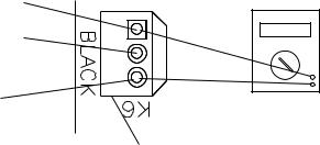
3)BC1 (infrared sensor) Power Supply (K6 connector): CB supplies 20VDC to BC1 and BC1 green LED is on. Diagnosis: Check that BC1 green LED is on. If not, check
for 20VDC between CB K6 #1 (DBU) and CB K6 #3 (BR). See Fig. 1. If 20VDC is not present, replace CB. If 20VDC is present, confirm that the yellow LED is not flashing or steady. If BC1 yellow LED is on or flashing, move ice away from lens. If no ice is present, clean the lens with a warm, clean damp cloth. If cleaning the lens does not work, replace BC1 (infrared sensor).
BC1 (infrared sensor) (20VDC) Closed 20VDC K6 #1 (DBU) to K6 #3 (BR) 20VDC K6 #1 (DBU) to K6 #2 (W) 0VDC K6 #2 (W) to K6 #3 (BR)
BC1 (infrared sensor) (20VDC) Open (yellow LED flashing or steady) 20VDC K6 #1 (DBU) to K6 #3 (BR) 0VDC K6 #1 (DBU) to K6 #2 (W) 20VDC K6 #2 (W) to K6 #3 (BR)
K6 #3 |
|
Red Positive |
|
|
Brown (BR) |
|
|
||
3 |
Test Lead |
20VDC |
||
K6 #2 |
||||
White (W) |
2 |
|
|
|
|
1 |
|
|
|
K6 #1 |
Black Negative |
Multimeter |
||
Dark Blue (DBU) |
Test Lead |
|
||
|
|
|
||
•K6 Connector
BC1 (Infrared Sensor)
Fig. 1
25
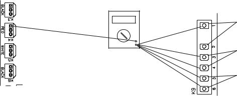
4) 5VDC Output Checks:
CB K9 Connector: Control Switch (CB K9 #1 and #2) (open contacts for icemaking, closed contacts for drain), High-Pressure Switch (CB K9 #3 and #4), Compressor
Control Relay/Gear Motor Protect Relay (K9 #5 and #6).
CB K8 Connector: Bin Control (2) (K8 #3 and #4) and Float Switch (K8 #5 (common), #6 (lower), and #7 (upper)).
When checking 5VDC control voltage, always place the red positive test lead from the multimeter to the CB white K5 pin closest to the CB red K4 connector. See Fig. 2.
Then place the black negative test lead from the multimeter to the corresponding pin to complete the 5VDC check.
Red positive test lead to K5 pin closest to K4 connector
Red Positive
Test Lead
5VDC |
Black Negative |
Control Switch |
|
||
|
Test Lead |
white/black (W/BK) |
Multimeter |
|
High-Pressure Switch |
|
yellow (Y) wires |
|
|
|
|
|
|
Compressor Control Relay/ |
|
|
Gear Motor Protect Relay |
|
|
(terminals #3 and #5) |
|
|
white/orange (W/O) |
Control Board K9 Connector
Fig. 2
a)Control Switch – CB K9 #1 (W/BK) and CB K9 #2 (W/BK):
5VDC is present between CB white K5 connector, pin closest to CB red K4 connector and CB K9 #1 (W/BK) at all times. If 5VDC is not present, replace CB. When the control switch is in the "ICE" position, the control switch contacts are open. 0VDC is present between CB white K5 connector, pin closest to CB red K4 connector and CB K9 #2 (W/BK). When in the "ICE" position, 5VDC is present between CB K9 #1 (W/BK) to CB K9 #2 (W/BK). When the control switch is in the "DRAIN" position, the control switch contacts are closed. 5VDC is present between CB white K5 connector, pin closest to CB red K4 connector, to CB K9 #1 (W/BK) or #2 (W/BK). If 5VDC is not present, replace CB. 0VDC is present from CB K9
#1 (W/BK) to CB K9 #2 (W/BK).
b)High-Pressure Switch – CB K9 #3 (Y) and CB K9 #4 (Y):
5VDC is present between CB K5 connector, pin closest to CB red K4 connector and
CB K9 #3 (Y) at all times. When the high-pressure switch is closed, 5VDC is present between CB K5 pin closest to CB K4 connector to CB K9 #3 (Y) and CB K9 #4 (Y). If 5VDC is not present, replace CB. When the high pressure switch is closed, 0VDC is present at CB K9 #3 (Y) to CB K9 #4 (Y). When the high pressure switch is open, 5VDC is present at CB K9 #3 (Y) to CB K9 #4 (Y). If the high-pressure switch is open and CB is not in alarm, replace CB. If 5VDC is present at CB K9 #3 (Y) and not at CB K9 #4 (Y), the high-pressure switch is open and CB sounds a 3-beep alarm.
Check continuity across the high pressure switch (CB K9 #3 (Y) and CB K9 #4 (Y)).
26
c)Compressor Control Relay/Gear Motor Protect Relay (CCR/GMPR) –
CB K9 #5 (W/O) and CB K9 #6 (W/O): 5VDC is present from CB white K5 connector, pin closest to CB red K4 connector to CB K9 #5 (W/O) at all times. If 5VDC is not present, replace CB. When CCR/GMPR terminals #3 (W/O) and #4 (W/O) are open (CCR/GMPR de energized), 5VDC is present between CB K9 #5 (W/O) and CB K9
#6 (W/O). When CCR/GMPR terminals #3 (W/O) and #4 (W/O) are closed (CCR/
GMPR energized), 5VDC is present between CB K9 #5 (W/O) and CB K9 #6 (W/O). When CCR/GMPR terminals #3 (W/O) & #5 (W/O) are open CB may be in an 8-beep alarm. See "III.A.2. LED Lights and Audible Alarm Safeties."
d)Bin Control (2) (mechanical stand-alone or backup) –
CB K8 #3 (GY) and CB K8 #4 (GY): 5VDC is present from CB white K5 connector, pin closest to CB red K4 connector to CB K8 #3 (GY) at all times. If 5VDC is not present, replace CB. When BC(2) is closed (calling for ice), 5VDC is present from CB white K5 connector, pin closest to CB red K4 connector, to CB K8 #3 (GY) and CB K8 #4 (GY). If 5VDC is not present to either CB K8 #3 (GY) or CB K8 #4 (GY), replace CB. If 5VDC is present at CB K8 #3 (GY) and not to CB K8 #4 (GY), BC(2) is open. See "II.D.2. Bin Control (2) (mechanical stand-alone or backup) Check."
e)Float Switch (LFS and UFS) – CB K8 #5 (BK) (common), CB K8 #6 (R) (upper), and CB K8 #7 (BU) (lower): 5VDC is present from CB white K5 connector pin closest to CB red K4 connector to CB K8 #5 (BK) (common) at all times. If not, replace CB. 5VDC is present from CB white K5 connector pin closest to CB red K4 connector
to CB K8 #6 (R) (upper) and CB K8 #7 (BU) (lower) when FS is open. If 5VDC is present between CB K8 #5 (BK) and CB K8 #6 (R) (upper) or CB K8 #7 (BU) (lower), FS is open. For further FS diagnostics, see "II.E. Float Switch Check and
Cleaning."
5)Fill "WTRIN" LED is on: 24VAC is present at CB K2 #9 (W/R) at all times. If not, confirm 24VAC from CB K2 #9 (W/R) to a neutral (LBU). When LFS open at startup or opens during normal operation, "WTRIN" LED turns on, fill timer (FT) starts, freeze timer (FZT) terminates (only during normal operation), and WV energizes. If LFS is open and "WTRIN" LED is off, confirm LFS status. See "II.E. Float Switch Check and Cleaning." If LFS is open and "WTRIN" LED is off, replace CB. If "WTRIN" LED is on
and WV is not energized, check for 24VAC at CB K2 #8 (O) to a neutral (LBU). If 24VAC is not present at CB K2 #8 (O), replace CB. "WTRIN" LED turns off once UFS closes.
If not, confirm UFS status. See "II.E. Float Switch Check and Cleaning." If UFS is closed and "WTRIN" LED is on, replace CB. If "WTRIN" LED is off and WV is open, check for 24VAC at CB K2 #8 (O). If 24VAC is present at CB K2 #8 (O), replace CB. If 24VAC is not present, check WV diaphragm.
6)Ice Purge Cycle "GM" LED is on: When UFS closes, GM delay timer starts (5 or
30 sec. depending on CB S1 dip switch #7). Once GM delay timer terminates, "GM"
LED turns on, GM and EH (-C model except FD-650) energize and 5-min. ice purge timer starts. If GM does not energize 30 sec. after UFS closes, confirm UFS status. See "II.E. Float Switch Check and Cleaning." If UFS is closed and GM LED does not turn, replace CB. If "GM" LED is on and GM and EH are off, check for 115VAC from CB K1 #2 to a neutral (W). If 115VAC is not present, check 115VAC power supply connections from power switch. If 115VAC is present, check for 115VAC from CB K1 #3 to a neutral (W). If 115VAC is present on CB K1 #2 and not on CB K1 #3, replace CB.
27
7)Freeze Cycle "GM" and "COMP" LED are on: The 5-min. ice purge timer terminates or the ice purge cycle bypass button ("SERVICE") is pressed, "COMP" LED turns on.
To bypass the 5-min. Ice Purge Cycle, press the "SERVICE" button on CB after the
"GM" LED turns on. WARNING! Risk of electric shock. Care should be taken not
to touch live terminals. 115VAC is present between CB X1 relay power supply brown (BR) or black (BK) wire and neutral (W) at all times. If not, check 115VAC power supply wire connections from power switch. If "COMP" LED is not on after 5-min. ice purge timer terminates, replace CB.
When "COMP" LED turns on, CR (if applicable) and compressor energize. If "COMP" LED is on and compressor relay (CR) (if applicable) and compressor are not, check for 115VAC from CB X1 relay power supply brown (BR) or black (BK) wire to neutral (W). If 115VAC is present, check X1 relay red (R), violet (V), or brown (BR)(FD-650 only) to neutral (W). If 115VAC is present on X1 relay brown (BR) or black (BK) and not on X1 relay red (R), violet (V), or brown (BR)(FD-650 only), replace CB.
8) Refill "WTRIN" LED is on: See "5) Fill "WTRIN" LED is on:" above.
Legend: BC1–bin control 1 (infrared sensor); BC(2)–bin control (2) (mechanical stand-alone or backup); CB–control board; CR–compressor relay; CCR/GMPR–compressor control relay/gear motor protect relay; EH–evaporator heater (-C model except FD-650); FS–float switch; GM–gear motor; LFS–lower float switch; UFS–upper float switch; WV–inlet water valve
28
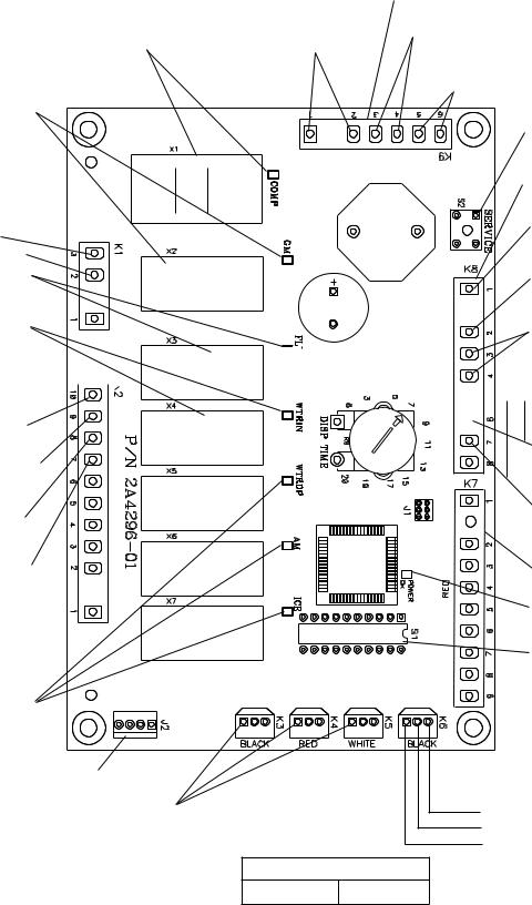
• "COMP" LED
(X1 Relay)
Comp, LLV, SLV
• "GM" LED
(X2 Relay)
GM
• K1 Connector
(115VAC)
GM, CCR/GMPR, EH, FM, FMR #3
115VAC Input #2
• "FLUSH" LED
(X3 Relay) (drain)
DV
• "WTRIN" LED
(X4 Relay)
WV
• K2 Connector 

(24VAC)
Drain Valve #10 (W/BU)
Control Transformer 24VAC Input
#9 (white/red)
Inlet Water Valve #8 (O)
Control Transformer 24VAC Input
#7 (white/red)
Water Dispensing |
|
|
Valve, Agitation |
|
|
Motor, and Ice |
|
|
Dispensing LEDs |
|
|
(not used on |
• J2 Connector-Open |
|
these models) |
||
|
||
5VDC common terminals |
||
•K3 Connector-Open
•K4 Connector-Open
•K5 Connector-Open
Control Board
• K9 Connector (5VDC)
Control Switch
#1 to #2 (white/black)


 (DRAIN)
Control Board
High-Pressure Switch #3 to #4 (yellow)
Compressor Control Relay Circuit/Gear Motor Protect Relay Circuit
#5 to #6 (white/orange)
• S2 "SERVICE" Button
(Ice Purge Cycle Bypass)
• K8 Connector
(24VAC and 5VDC)
Control Transformer 24VAC Input
#1 (white/red)
Control Transformer 24VAC Neutral
#2 (light blue)
Bin Control (2) (mechanical) #3 & #4 (gray) (5VDC)

 Float Switch-Common
  #5 (black) (5VDC)
Upper Float Switch #6 (red) (5VDC)
Lower Float Switch #7 (blue) (5VDC)
• K7 Connector-Open
• "POWER OK" LED
• S1 Dip Switch
3 2 1 
• K6 Connector (20VDC)
Bin Control 1 (infrared sensor) (dark blue)
(white, signal (common)) (brown (ground))
Part Number 2A48054-01
Fig. 3
29
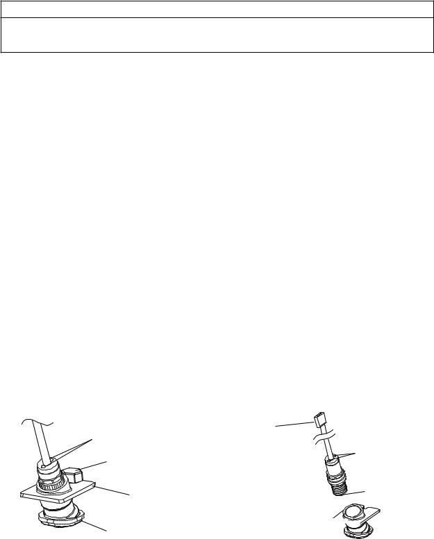
D. Bin Control Check
1. Bin Control 1 (infrared sensor) Check
IMPORTANT
Make sure CB S1 dip switch 7 is in the "ON" position. This allows the control board to monitor BC1 (infrared sensor) along with BC2 (mechanical) backup bin control.
1)Turn off the power supply.
2)Remove the front panel, top panel, and control box cover.
3)Confirm that CB S1 dip switch 1, 2, 3 are in the proper position for your application. See "III.B.2. BC1 (Infrared Sensor) Shutdown Delay (S1 dip switch 1, 2, 3)."
4)Confirm that BC1 is connected to CB K6 connector. Wipe down BC1 lens with a warm, clean, damp cloth. If the bottom of the icemaker is not accessible in your application, remove the thumbscrew securing the BC1 housing, then remove the housing from the base. See Fig. 4.
5)Move the control switch to the "ICE" position, then move the power switch to the "ON" position.
6)Turn on the power supply to start the automatic icemaking process. Check that BC1 green LED is on. The BC1 green LED confirms 20VDC power from CB to BC1 and remains on constantly. Diagnosis: If the BC1 green LED is not on, confirm 20VDC
at CB K6 #1 (DBU) to CB K6 #3 (BR). If 20VDC is present and the BC1 green LED is off, replace BC1. If not, see step "3) BC1 (infrared sensor) Power Supply," under "II.C.
Control Board Check.
7)Make sure CB "GM" LED is on. There is a delay of at least 30 sec. before the "GM" LED turns on after power-up. After CB "GM" LED turns on, press CB "SERVICE" button to bypass the 5-min. ice purge cycle. WARNING! Risk of electric shock. Care should be taken not to touch live terminals.
BC1 (infrared sensor) |
|
||
|
Connector |
|
|
LEDs |
(20VDC from |
|
|
|
K6 connector on |
LEDs |
|
Thumbscrew |
control board) |
||
|
|||
Lens
Housing
Housing 


Lens
Fig. 4
30
Loading...