


CR2A-HS
Table of contents
 Loading...
Hoshizaki
“A Superior Degree
of Reliability”
www.hoshizaki.com
Models
CR2A-FS
CR2A-HS
CF2A-FS
CF2A-HS
Commercial Series
Refrigerated Kitchen Equipment
Hoshizaki America, Inc.
Number: 71309
Issued: 7-14-2011
PARTS LIST

2
CONTENTS
Auxiliary Codes ...................................................................................................................... 3
Note About Ordering Parts .................................................................................................... 3
A. Reach-In Assembly ............................................................................................................ 4
B. Refrigeration Circuit ........................................................................................................... 9
CR2A-FS, CR2A-HS ......................................................................................................... 9
CF2A-FS, CF2A-HS .........................................................................................................11
C. Control Box Assembly ..................................................................................................... 14
CR2A-FS, CR2A-HS ....................................................................................................... 14
CF2A-FS, CF2A-HS ........................................................................................................ 15
D. Door-Right Hinged ........................................................................................................... 16
Full Solid: CR2A-FS, CF2A-FS ........................................................................................ 16
Half Solid: CR2A-HS ....................................................................................................... 19
Half Solid: CF2A-HS ........................................................................................................ 20
E. Door-Left Hinged ............................................................................................................. 22
Full Solid: CR2A-FS, CF2A-FS ........................................................................................ 22
Half Solid: CR2A-HS ....................................................................................................... 25
Half Solid: CF2A-HS ........................................................................................................ 26
F. Accessories & Packaging ................................................................................................. 28

3
Auxiliary Codes
CR2A-FS V-5 April 2010
V-6 June 2010
V-7 September 2010
A-5 January 2011
CR2A-HS V-5 April 2010
V-6 June 2010
CF2A-FS V-5 May 2010
V-6 September 2010
A-5 January 2011
CF2A-HS V-5 May 2010
V-6 September 2010
Auxiliary Code Breakdown
The auxiliary code is the rst two characters in the serial number. The rst character
indicates the year. Years progress or regress in alphabetical order. The series runs from
"A" through "V" and the letters "I" and "O" are skipped. The second character indicates
signicant part changes within a year. Base is "0" and this number advances for each
change. In cases where there is a letter in parentheses, this designates the month. This is
the last character in the serial number. The series runs from "(A)" through "(M)" and the
letter "(I)" is skipped. This designation is only included when identifying a parts change
within an auxiliary code.
Note About Ordering Parts
Most assemblies cannot be ordered as complete units; parts in the assemblies generally
must be ordered separately.
4
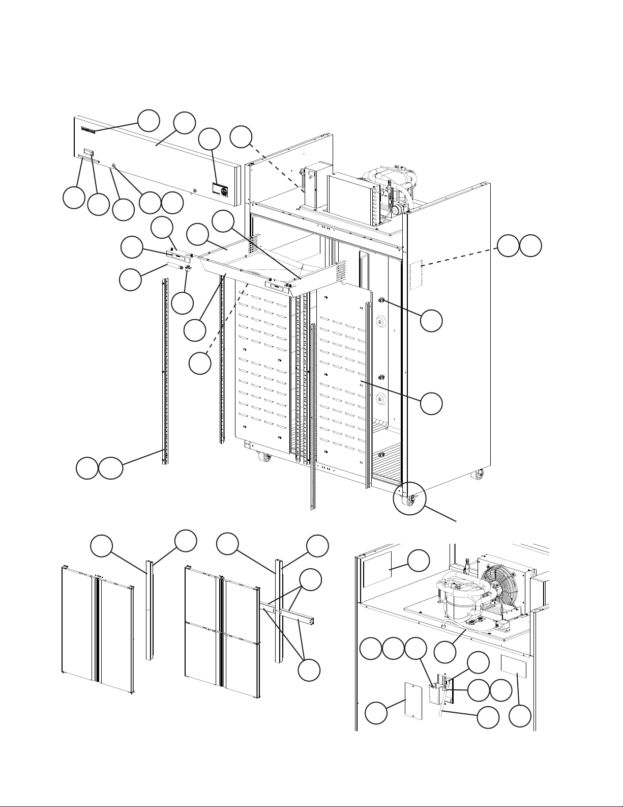
A. Reach-In Assembly
CR2A-FS, CR2A-HS, CF2A-FS, CF2A-HS
V-5 to A-5
For casters, see
section "F"
1 2
3
29
30
31 32
20
21
4
5
6
7
8
37
22
23
15
16
12
13
14
17
18
19
24
25
26
27
28
9
10 11
33 34
35
36
For doors, see section "D" and "E"
19a
26
27
5
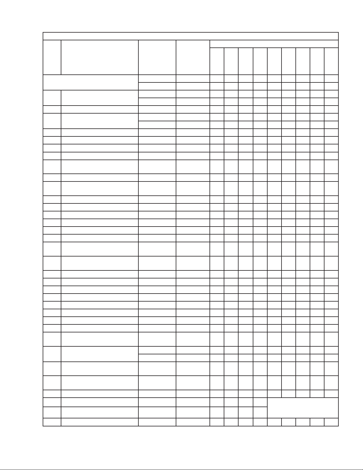
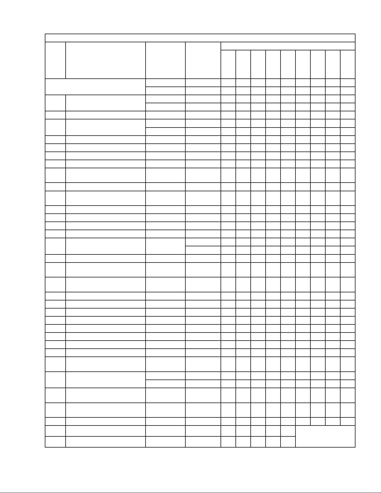
Title: A. Reach-In Assembly Models: CR2A-FS, CR2A-HS
Index
No. Description
Material or
Model Number Part Number
Required Number
V-5
(D)
V-5
(E-F)
V-6
(G-H)
V-7
(J)
V-7
(K)
V-7
(L)
to
A-5
Reach-In Assembly
Order Assembly Parts Individually
CR2A-FS 1A1982A01 1 1 1 1 1 1
CR2A-HS 1A1987A01 1 1 1 1 1 1
1 Nameplate CR2A-FS 2A5306-05 1 1 1 1 1 1
CR2A-HS 2A5306-06 1 1 1 1 1 1
2 Nameplate Cover 4A3727-01 1 1 1 1
3 Wiring Label Rev 4 2A5881-01 1 1 -
Rev 5 2A5881-01 1 1 1 1
4 Reservoir Cover 3A5898-01 1 1 1 1 1 1
5 Caution Label 4A1931-01 1 1 1 1 1 1
6 Ground Screw 433304-02 1 1 1 1 1 1
7 Front Panel 2A5884-01 1 1 1 1 1 1
8 Display Module (includes
mounting clips)
4A4862-01 1 1 1 1 1 1
9 Door Switch 3A1826-01 2 2 2 2 2 2
10 Door Lock (includes 2keys and
1 of item 11)
4A4924-01 2 2 2 2 2 2
11 Door Lock Cam 4A4925-01 2 2 2 2 2 2
12 Commercial Label 3A5816-01 1 1 1 1 1 1
13 Emblem 4A0560-01 1 1 1 1 1 1
14 Air Filter Label 426177-01 1 -
15 Evaporator Fan Shroud 3A5906G01 1 1 1 1 1 1
16 Fan Guard 4A4860-01 2 2 2 2 2 2
17 Right Side Evaporator Fan
Shroud
3A6629G01 1 1 1 1 1 1
18 Left Side Evaporator Fan
Shroud
3A6638G01 1 1 1 1 1 1
19 Pilaster 3A0145-22 8 8 8 8 8 8
19a Truss Head Screw 5×10, SS 7C32-0510 24 24 24 24 24 24
20 Duct Stand Off 4A4874-01 12 12 12 12 12 12
21 Rear Duct Panel 2A5205-01 2 2 2 2 2 2
22 Light Plate 3A5496-21 2 2 2 2 2 2
23 Light Socket 4A4443-01 2 2 2 2 2 2
24 Light Bulb 4A4444-01 2 2 2 2 2 2
25 Warning Label 4A2968-03 2 2 2 2 2 2
26 Vertical Mullion Face (includes
heater)
2A5906G01 1 1 1 1 1 1
27 Vertical Mullion Thermal Break CR2A-FS 2A5908G01 1 1 1 1 1 1
CR2A-HS 2A5908G02 1 1 1 1 1 1
28 Horizontal Mullion Face
(includes heater)
CR2A-HS 3A5910G01 2 2 2 2 2 2
29 Horizontal Mullion Thermal
Break
CR2A-HS 3A5951G01 2 2 2 2 2 2
30 Reservoir 3A5565-01 1 1 1 1 1 1
31 Float Switch Bracket 3A5560-01 1 1 1 1 V-7 (K) and later, see
"Condensate Pump" in
section "B"
32 Float Switch 4A4937-01 1 1 1 1
33 Rubber Gasket 413854-03 1 1 1 -
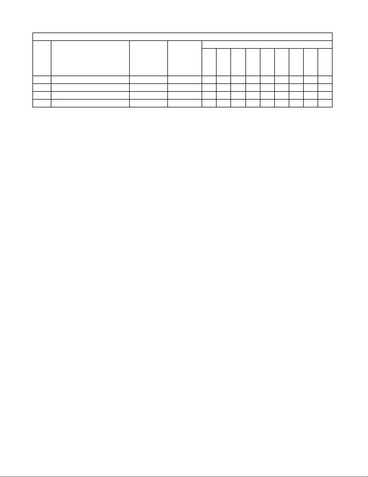
6
Title: A. Reach-In Assembly Models: CR2A-FS, CR2A-HS
Index
No. Description
Material or
Model Number Part Number
Required Number
V-5
(D)
V-5
(E-F)
V-6
(G-H)
V-7
(J)
V-7
(K)
V-7
(L)
to
A-5
34 Drain Fitting 4A2792-01 1 1 1 1 1 1
35 Silicone Hose L=150 7730I3812 1 1 1 1 1 1
36 Drain Boot 4A4938-01 1 1 1 1 1
37 PVC Tubing L=860 7716I1438 1 1
7
Title: A. Reach-In Assembly Models: CF2A-FS, CF2A-HS
Index
No. Description
Material or
Model Number Part Number
Required Number
V-5
V-5
(E-F)
V-5
(G)
V-5
(H) V-6
V-6
(K)
V-6
(L)
to
A-5
Reach-In Assembly
Order Assembly Parts Individually
CF2A-FS 1A2017A01 1 1 1 1 1 1 1
CF2A-HS 1A2032A01 1 1 1 1 1 1 1
1 Nameplate CF2A-FS 2A5306-07 1 1 1 1 1 1 1
CF2A-HS 2A5306-08 1 1 1 1 1 1 1
2 Nameplate Cover 4A3727-01 1 1 1 1 1
3 Wiring Label Rev 0 2A6010-01 1 1 1 -
Rev 1 2A6010-01 1 1 1 1
4 Reservoir Cover 3A5898-01 1 1 1 1 1 1 1
5 Caution Label 4A1931-01 1 1 1 1 1 1 1
6 Ground Screw 433304-02 1 1 1 1 1 1 1
7 Front Panel 2A5884-01 1 1 1 1 1 1 1
8 Display Module (includes
mounting clips)
4A4862-01 1 1 1 1 1 1 1
9 Door Switch 3A1826-01 2 2 2 2 2 2 2
10 Door Lock (includes 2keys and
1 of item 11)
4A4924-01 2 2 2 2 2 2 2
11 Door Lock Cam 4A4925-01 2 2 2 2 2 2 2
12 Commercial Label 3A5816-02 1 1 1 1 1 1 1
13 Emblem 4A0560-01 1 1 1 1 1 1 1
14 Air Filter Label 426177-01 1 1 -
15 Evaporator Fan Shroud 3A5906G01 1 1 1 -
3A6212G01 1 1 1 1
16 Fan Guard 4A4860-01 2 2 2 3 3 3 3
17 Right Side Evaporator Fan
Shroud
3A6629G01 1 1 1 1 1 1 1
18 Left Side Evaporator Fan
Shroud
3A6638G01 1 1 1 1 1 1 1
19 Pilaster 3A0145-22 8 8 8 8 8 8 8
19a Truss Head Screw 5×10, SS 7C32-0510 24 24 24 24 24 24 24
20 Duct Stand Off 4A4874-01 12 12 12 12 12 12 12
21 Rear Duct Panel 2A5205-01 2 2 2 2 2 2 2
22 Light Plate 3A5496-21 2 2 2 2 2 2 2
23 Light Socket 4A4443-01 2 2 2 2 2 2 2
24 Light Bulb 4A4444-01 2 2 2 2 2 2 2
25 Warning Label 4A2968-03 2 2 2 2 2 2 2
26 Vertical Mullion Face (includes
heater)
2A5906G01 1 1 1 1 1 1 1
27 Vertical Mullion Thermal Break CF2A-FS 2A5908G01 1 1 1 1 1 1 1
CF2A-HS 2A5908G02 1 1 1 1 1 1 1
28 Horizontal Mullion Face
(includes heater)
CF2A-HS 3A5910G01 2 2 2 2 2 2 2
29 Horizontal Mullion Thermal
Break
CF2A-HS 3A5951G01 2 2 2 2 2 2 2
30 Reservoir 3A5565-01 1 1 1 1 1 1 1
31 Float Switch Bracket 3A5560-01 1 1 1 1 1 V-6 (K) and later, see
"Condensate Pump" in
section "B"
32
Float Switch 4A4937-01 1 1 1 1 1
8
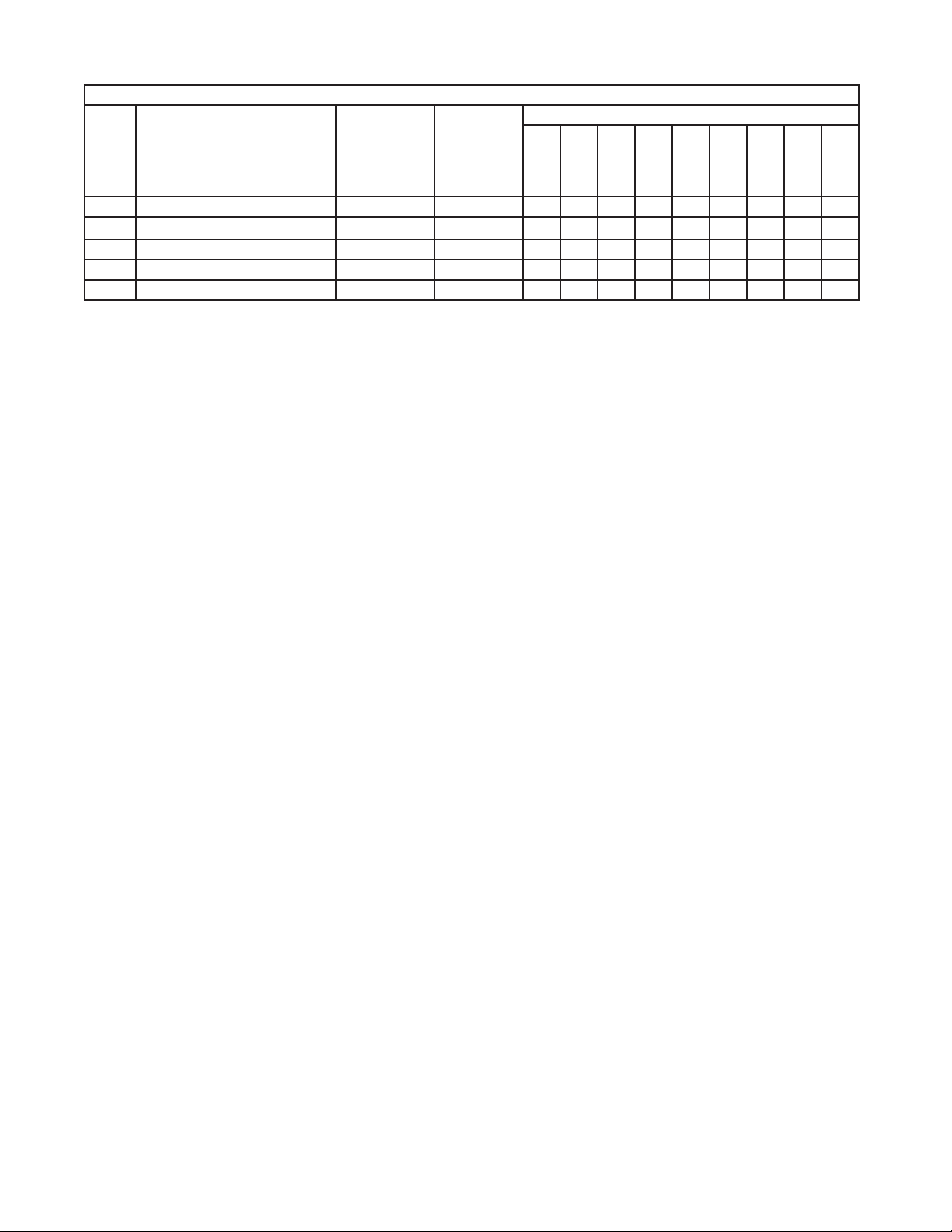
Title: A. Reach-In Assembly Models: CF2A-FS, CF2A-HS
Index
No. Description
Material or
Model Number Part Number
Required Number
V-5
V-5
(E-F)
V-5
(G)
V-5
(H) V-6
V-6
(K)
V-6
(L)
to
A-5
33 Rubber Gasket 413854-03 1 1 1 1 -
34 Drain Fitting 4A2792-01 1 1 1 1 1 1 1
35 Silicone Hose L=150 7730I3812 1 1 1 1 1 1 1
36 Drain Boot 4A4938-01 1 1 1 1 1 1
37 PVC Tubing L=860 7716I1438 1 1
9
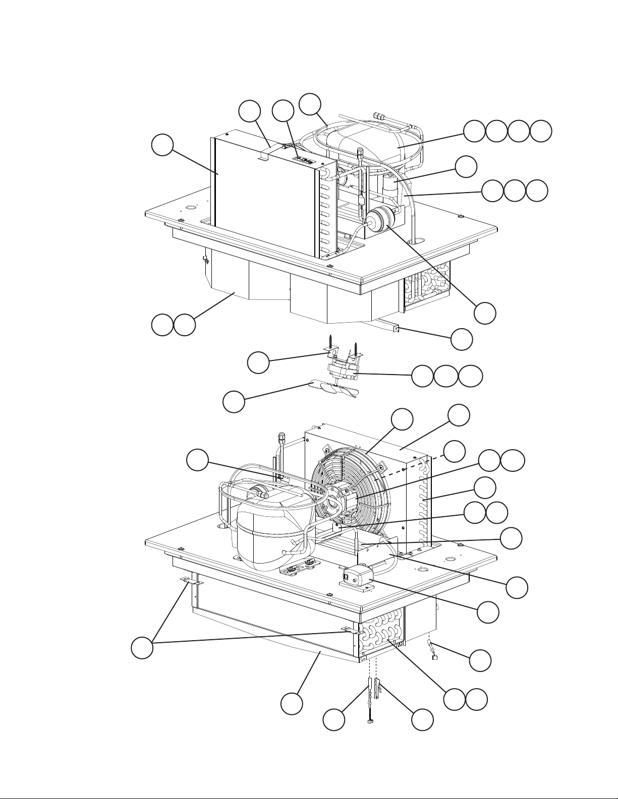
1
2
3
1a 1b 1c
8
20
21
4
5
6
7
9
10
11
22
23
15
16
12
31a
13
14
17
18
17a
19
31b
24 25
26
27
29
28
34
30
31
B. Refrigeration Circuit
CR2A-FS, CR2A-HS
V-5 to A-5
33
32
Loading...