


CT5.1

CT5.1
TREADMILL OWNER’S MANUAL
MANUEL D’UTILISATION DU TAPIS ROULANT
Read the TREADMILL GUIDE before using this OWNER’S MANUAL.
Lire le GUIDE DU TAPIS ROULANT avant de se servir du présent MANUEL D’UTILISATION.

3 ENGLISH
21 FRANÇAIS
2

ASSEMBLY
WARNING
There are several areas during the assembly process that special attention must be paid. It is very important to follow the assembly
instructions correctly and to make sure all parts are firmly tightened. If the assembly instructions are not followed correctly, the
treadmill could have parts that are not tightened and will seem loose and may cause irritating noises. To prevent damage to the
treadmill, the assembly instructions must be reviewed and corrective actions should be taken.
Before proceeding, find your treadmill’s serial number located near the on/off
power switch and power cord and enter it in the space provided below.
ENTER YOUR SERIAL NUMBER IN THE BOX BELOW:
SERIAL NUMBER:
MODEL NAME: HORIZON CT5.1 TREADMILL
» Refer to the SERIAL NUMBER and MODEL NAME when calling for service.
» Be sure to enter both the SERIAL NUMBER and MODEL NAME on your warranty card.
3
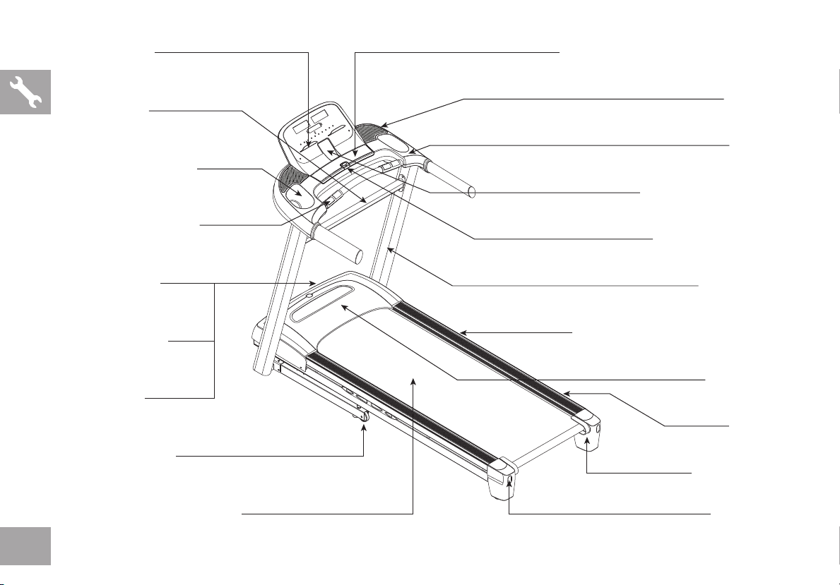
RE ADING RACK
TOU CH PAD PANEL AND DI SPLAY WINDO WS
SUPPO RT BAR
WATE R BOTT LE HOL DE R
GRIP P UL SE HANDRAILS
ON/OFF S WITCH
CIRCU IT BREAKER
POWER CO RD
TRANSPO RT WHEEL
SPEAKERS
CONSO LE
IPOD/MP3 P LAYER POCKET
SAF ET Y K EY PL ACEMENT
CONSO LE MAS T
FOOT LO CK LATCH ( UN DE RN EATH DECK)
MOTOR C OVER
SIDE RAIL
ROL LER END CAP
RUNNI NG BELT / RUNNIN G D ECK
RE AR ROL LER
ADJ US TMENT BO LTS
4
TOOLS INCLUDED:
F Screwdriver
F 6 mm T-Wrench
F 5 mm L-Wrench
F 4 mm L-Wrench
PARTS INCLUDED:
F 1 Console Assembly
F 2 Console Masts
F 1 Support Bar
F 2 Bottom Console Covers
F 5 Hardware Bags
F 1 Safety Key
F 1 Audio Adapter Cable
F 1 Bottle of Silicone Lubricant
(for 2 applications)
PRE ASSEMBLY
UNPACKING
Place the treadmill carton on a level flat surface. It is recommended that you place a
protective covering on your floor. Take CAUTION when handling and transporting this
unit. Never open box when it is on its side. Once the banding straps have been removed,
do not lift or transport this unit unless it is fully assembled and in the upright folded
position, with the lock latch secure. Unpack the unit where it will be used. The enclosed
treadmill is equipped with high-pressure shocks and may spring open if mishandled.
Never grab hold of any portion of the incline frame and attempt to lift or move the treadmill.
WARNING
DO NOT ATTEMPT TO LIFT THE TREADMILL! Do not move or lift treadmill
from packaging until specified to do so in the assembly instructions. You may
remove the plastic wrap from console masts.
WARNING
NEED HELP?
If you have questions or if
there are any missing parts,
contact Customer Tech
Support. Contact information
is located on the back panel
of this manual.
FAILURE TO FOLLOW THESE INSTRUCTIONS COULD RESULT IN INJURY!
NOTE: During assembly, do not completely tighten any screws or bolts until step 4 is
complete!
NOTE: A light application of grease may aid in the installation of hardware. Any grease,
such as lithium bike grease is recommended.
5
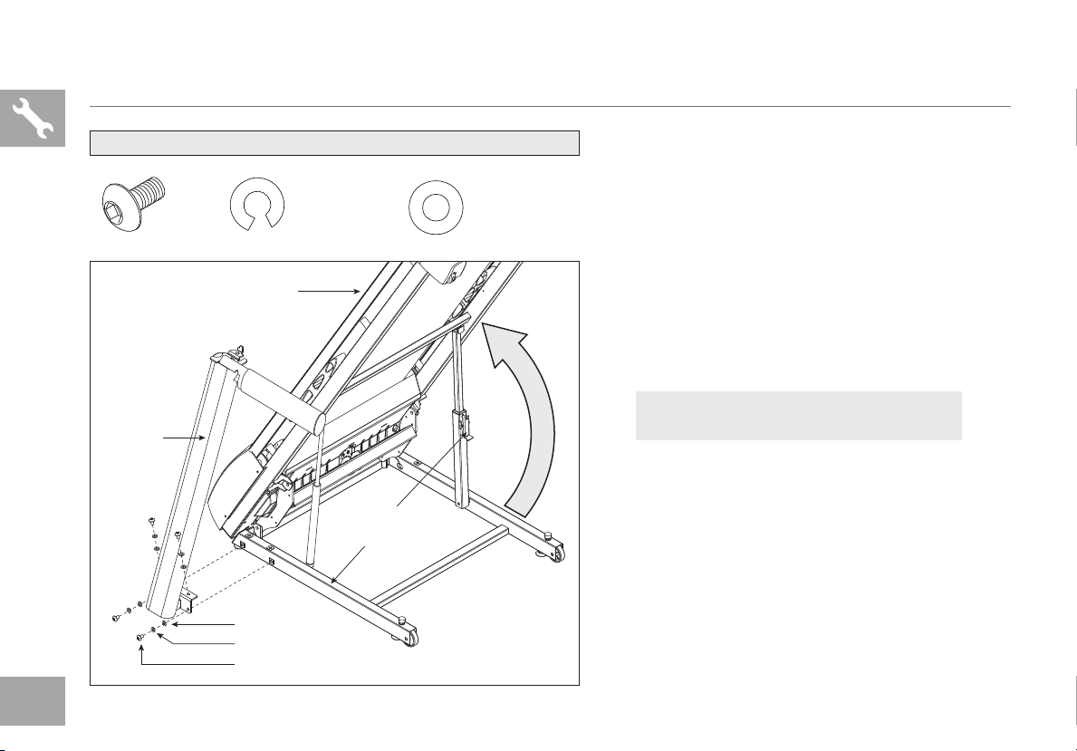
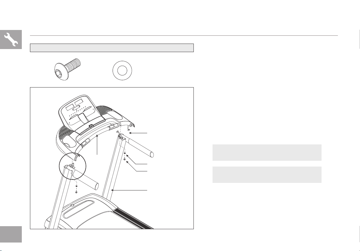
ASSEMBLY STEP 1
LEFT
CONSOLE
MAST
HARDWARE BAG 1 CONTENTS :
BOLT (A)
20 mm
Qty: 4
RUNNING DECK
FLAT WASHERS (C)
SPRING WASHERS (B)
BOLTS (A)
SPRING WASHER (B)
15 mm
Qty: 4
FOOT LATCH
BASE FRAME
FLAT WASHER (C)
15 mm
Qty: 4
A Cut the yellow banding straps and lift the
running deck upward until the foot
latch locks. Remove all contents from
underneath the running deck.
B Open hardware bag 1.
C With the running deck in the raised
position, attach the left console mast
to the base frame using 4 bolts (a),
4 spring washers (b) and 4 flat
washers (c).
NOTE: Do not completely tighten any
screws or bolts until
step 4 is complete!
6
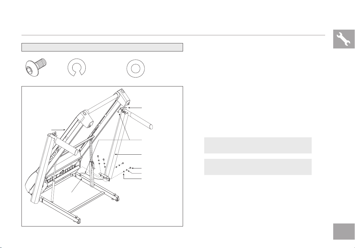
ASSEMBLY STEP 2
RUNN ING DECK
HARDWARE BAG 2 CONTENTS :
BOLT (A)
20 mm
Qty: 4
BASE FRAME
SPRING WASHER (B)
15 mm
Qty: 4
FLAT WASHER (C)
15 mm
Qty: 4
LEAD WIRE
CONSOLE CABLE
RIGHT CON SOLE MAST
BOLTS (A)
SPRIN G WASHER S (B)
FLAT WASHERS (C)
A Open hardware bag 2.
B Pull lead wire through right console
mast. After pulling the lead wire through the
mast, the top of the console cable should
be located at the top of the mast. Detach and
discard the lead wire.
C With the running deck in the raised
position, attach the right console
mast to the base frame using 4 bolts
(a), 4 spring washers (b) and 4 flat
washers (c).
NOTE: Do not completely tighten any
screws or bolts until
NOTE: Be careful not to pinch any wires
while assembling the right console mast.
step 4 is complete!
7
ASSEMBLY STEP 3
ASSEMBLE
LEFT SIDE
FIRST
HARDWARE BAG 3 CONTENTS :
BOLT (D)
25 mm
Qty: 2
CONSOLE
FLAT WASHER (E)
16 mm
Qty: 2
CONSOLE CABLES
FLAT WASHER (E)
BOLT (D)
CONSOLE MAST
A Disengage the deck lock latch with your
foot to lower the running deck.
B Open hardware bag 3.
C Gently place the console on top of the
console masts. Attach the left side first
using 1 bolt (d) and 1 flat washer (e).
D Connect the console cables, carefully
tucking wires in masts to avoid damage.
E Attach the right side of the console
using 1 bolt (d) and 1 flat washer (e).
NOTE: Do not completely tighten any
screws or bolts until
NOTE: Be careful not to pinch any wires
while assembling the masts.
step 4 is complete!
8
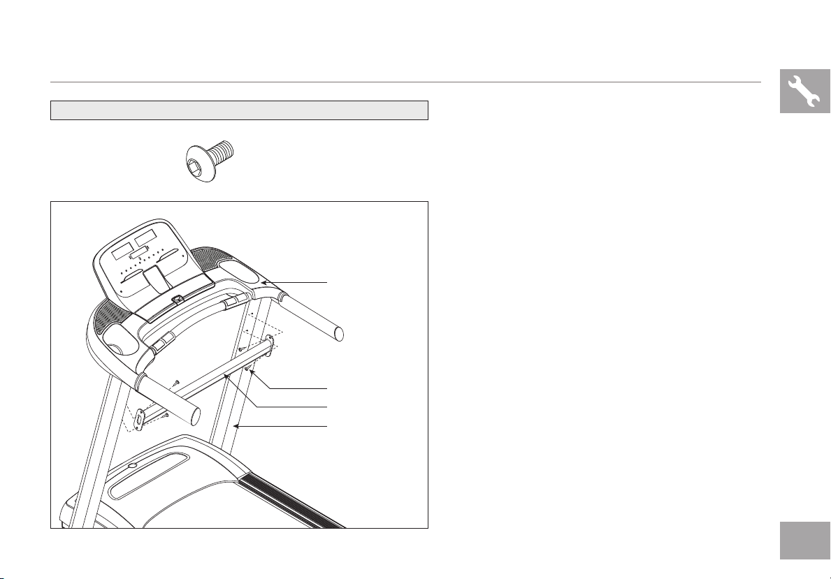
ASSEMBLY STEP 4
HARDWARE BAG 4 CONTENTS :
BOLT (H)
15 mm
Qty: 4
A Open hardware bag 4.
B Align support bar with holes in console
masts.
C Insert bolts (h) into all 4 holes of the
support bar.
Note: look into holes in the right mast before
inserting bolts to avoid pinching cables.
D Tighten all bolts completely.
CONSOLE
BOLTS (H)
SUPPORT BAR
CONSOLE MAST
9
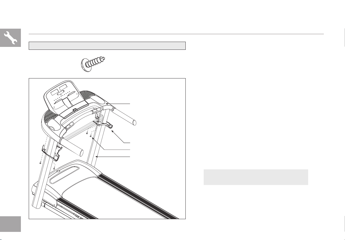
ASSEMBLY STEP 5
HARDWARE BAG 5 CONTENTS :
SCREW (G)
15 mm
Qty: 4
CONSOLE
BOTTOM CONSOLE COVER
SCREWS (G)
CONSOLE MAST
A Open hardware bag 5.
B Slide right bottom console cover up
console mast and align screw holes. Attach
bottom console cover to console
using 2 screws (g).
C Repeat on other side.
D Connect power plug to a power outlet. The ON/
OFF switch is located next to the power cord.
Flip this switch to the ‘ON’ position, so that
the switch is lit. You will hear a beep and the
console will turn on.
E Before the first use, lubricate the treadmill
deck by following the instructions in the
MAINTENANCE section in the TREADMILL
GUIDE.
YOU ARE FINISHED!
10

TREADMILL OPERATION
This section explains how to use your treadmill’s console and programming. The BASIC OPERATION section in the
TREADMILL GUIDE has instructions for the following:
• LOCATION OF THE TREADMILL
• USING THE SAFETY KEY
• FOLDING THE TREADMILL
• MOVING THE TREADMILL
• LEVELING THE TREADMILL
• TENSIONING THE RUNNING BELT
• CENTERING THE RUNNING BELT
• USING THE HEART RATE FUNCTION
11
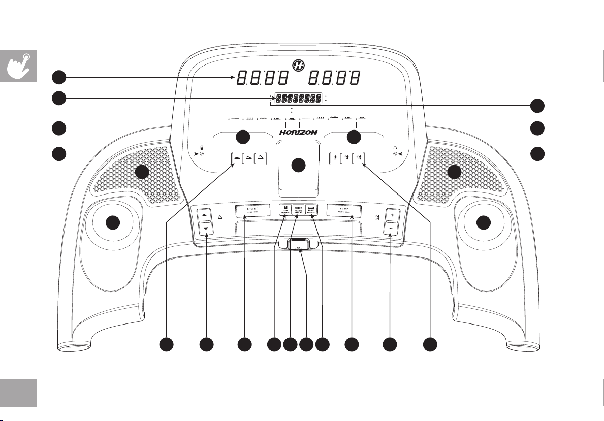
TIME DISTANCE
A
CALORIES
B
INCLINE
MANUAL
WEIGHT
INTERVALS
LOSS
% COMPLETE
SCAN
ROLLING
HILLS
D
HEART RATE
SPEED
C
SAVED
SAVED
SAVED
SAVED
SAVED
WEIGHT
MANUAL
INTERVALS
HILLS
ROLLING
LOSS
E
U U
™
Q
P P
My K E Y S
Press and hold a MyKEY
for three seconds to set
key to current incline.
™
LOW HIGHMED
O
SLOW MED
™
My K E Y S
™
Press and hold a MyKEY
for three seconds to set
FAST
key to current speed.
R
12
T T
F J SL KHM G I
SPE EDINC LIN E
N
 Loading...