


YZ667A1060
1
Wireless Domestic Heating Zoning System
INSTALLATION GUIDE
YZ667A1060
TABLE OF CONTENTS
Section Page
1 General.................................................. 1
2 Technical Information .......................... 1
3 Factory Conguration.......................... 2
4 HC60NG Relay Module......................... 3
5 CM67z Room Unit................................. 4
6 HR80UK Radiator Controller ............... 5
7 System Testing ..................................... 6
7.1 Service mode......................................................6
8 Changing the Conguration................ 7
8.1 Parameters of the CM67z...................................7
8.2 Changing or adding a HR80UK to a zone ........8
8.3 Built -in sensor conguration ...........................9
8.4 Adding a HC60NG Zone valve controller .........9
8.5 Resetting a Bound HR80UK ..............................9
9 Trouble Shooting................................ 10
9.1 Trouble Shooting Guide...................................10
9.2 Manual adaptation............................................11
1 GENERAL
The CM Zone Wireless Domestic Heating Zoning System
offers high levels of comfort and energy savings for the
home. It provides the ability to control two individual zones
at different comfort levels and at different times. A typical
example being the living areas and the bedrooms being
controlled separately.
The standard CM Zone Pack contains a Room Unit, a Relay
Module and six Radiator Controllers all pre-bound with three
Radiator Controllers bound to Zone 1 and three bound to
Zone 2. The System can be expanded or modied and the
methods used are described within this Guide.
To get the best from the installed system it is recommended
to use Honeywell VT15, VT117 or VT200 TRV bodies and a
Honeywell DU145 Automatic Bypass Valve.
For application support please contact your nearest
Honeywell salesman, for technical assistance please contact
the Honeywell Technical Help Desk, details are on the back
page.
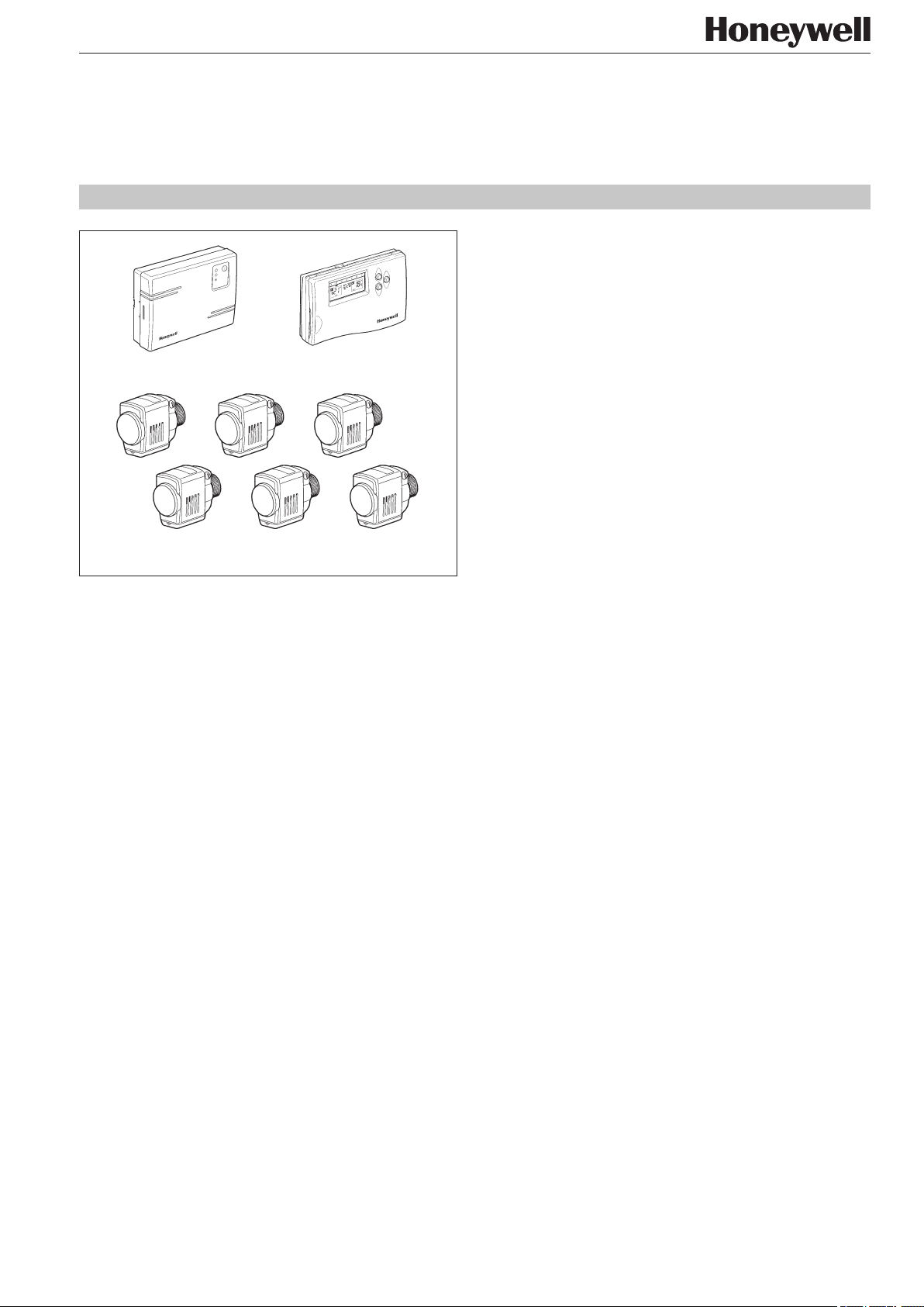
HC60NG Relay Module CM67z Room Unit
HR80UK Radiator Controllers
42010824-003 R1
2 TECHNICAL INFORMATION
Type numbers
CM67z - Room Unit (x1)
HR80UK - Radiator Controller (x6)
HC60NG - Relay module (x1)
Material
Housings made of plastics (ABS).
Dimensions
CM67z - 155 x 105 x 30 mm. (l x h x d)
HR80UK - 50 x 80 x 105 mm. (l x h x d)
HC60NG - 131 x 97 x 36 mm. (l x h x d)
Power
CM67z - 2 x 1.5 V IEC LR6 (AA) Alkaline cells
HR80UK - 2 x 1.5 V IEC LR6 (AA) Alkaline cells
HC60NG - 230V~ 50Hz powered
Electrical wiring (only for HC60NG)
Mains power supply
Relay output rating: 24-230 V~, 10A resistive,
3A inductive 0.6 p.f.
Programming Capability
2 individual heating programs
7 days with 6 temperature change times per day
Approvals
DIN EN ISO 9001/14001, CE, EN60730-1 (1995),
EN55014-1 (1997), EN55014-2 (1996),
ETSI EN300 220-3 (2000), ETSI EN301 489-3 (2000)
2
3
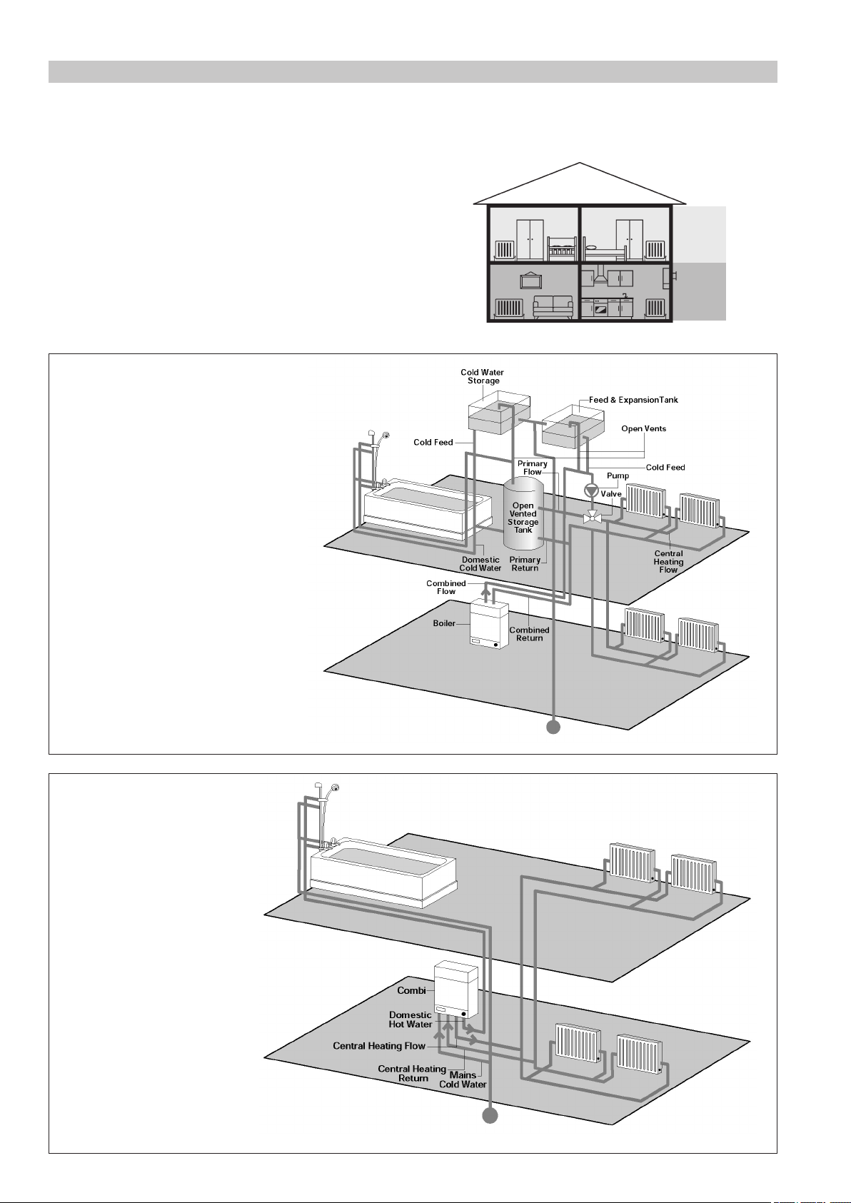
Section 3: Factory Conguration
Zoning Example
Zone 1: Living Room + Kitchen (downstairs)
Zone 2: Bedrooms (upstairs)
Zone 1
Zone 2
The Hydronic Zoning kit is factory pre-congured and has the
following components:
• Zone 1 - Three HR80UK Radiator controllers labelled 1
• Zone 2 - Two HR80UK Radiator controllers labelled 2
• HC60NG - Relay box
• CM67z - Room Unit
To change this factory conguration or to add components
please see Section 8: Changing the Conguration.
A typical traditional system with open
vented hot water storage tank
Conventional Boilers
These are used in traditional central
heating systems in the UK.
A typical COMBI system
Combination Boilers
With a combination boiler,
hot water and central heating
requirements are provided
from the one unit.
3
5 6
3 4
1
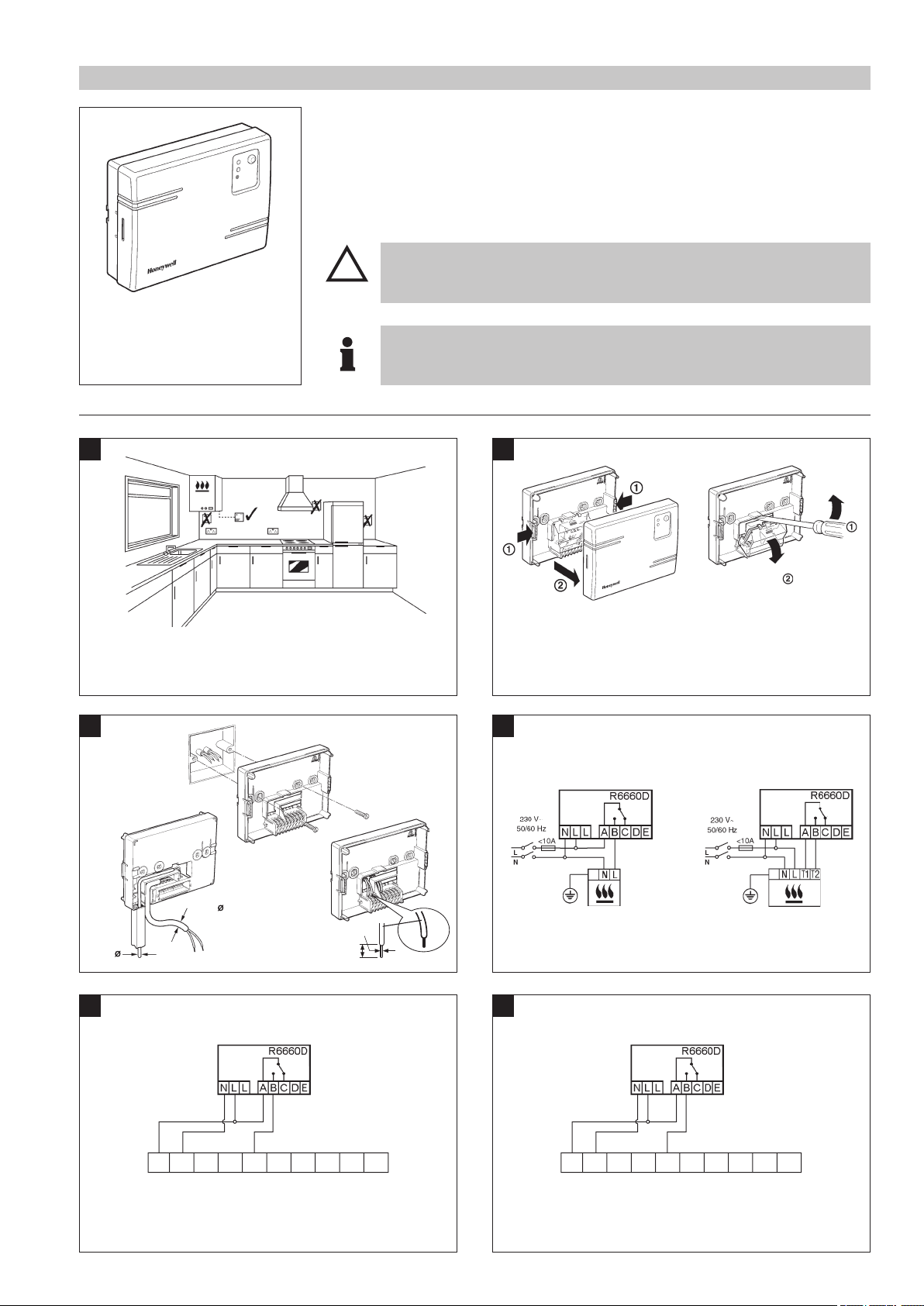
The HC60NG is a radio frequency (RF) device and for the best perform-
ance should be installed in an open space. Leave at least 30cm distance
from any metal objects including wall boxes and the boiler.
2
NOTE:
The HC60NG contains no user serviceable parts. It should be opened and
installed by qualied installer only.
WARNING:
Electrostatic sensitive device! Do not touch the circuit board.
> 7mm
< 7mm
1.0-2.5mm²
6mm max.
NOTE:
Install in accordance with local wiring regulations
CAUTION:
Observe ambient temperature and current limits (see HC60NG wiring label)
Section 4:
HC60NG Relay Module
Caution!
!
When selecting the operating site ensure that the distance to wireless
devices such as wireless headphones, cordless phones etc. is approx.
1-2m according to the DECT standard.
The HC60NG Relay Module is an integral part of the CM Zone Control System. It is
designed to control a Domestic Boiler, Valve, pump or Electric Heating appliances.
In the standard CM Zone Pack the HC60NG Relay Module is congured to control a Boiler
based upon demand signals received from the HR80UK Radiator Controllers either directly
or via a ‘Y Plan’ / ‘S Plan’ connection described below.
For control of other applications see Section 8: Changing the Conguration.
Please note: Maximum wire size 2.5mm
2
. SPDT relay suitable for
24...230V~, 10A resistive, 3A inductive
Honeywell ‘Y Plan’ Connections Honeywell ‘S Plan’ Connections
NOTE:
For existing ’Y Plan’ remove only Room Thermostat connections from
Junction Box Terminals and replace with Connections to HC60NG.
NOTE:
For existing ’S Plan’ remove only Room Thermostat connections from
Junction Box Terminals and replace with Connections to HC60NG.
HC60NG Relay Module
Typical Burner / Boiler connections
a. Burner (direct control)
HC60NG
b. Combi boiler
HC60NG
1 2 3 4 5 6 7 8 9 10
Typical ‘Y Plan’ Junction Box
HC60NG
1 2 3 4 5 6 7 8 9 10
Typical ‘S Plan’ Junction Box
HC60NG
4
5
Section
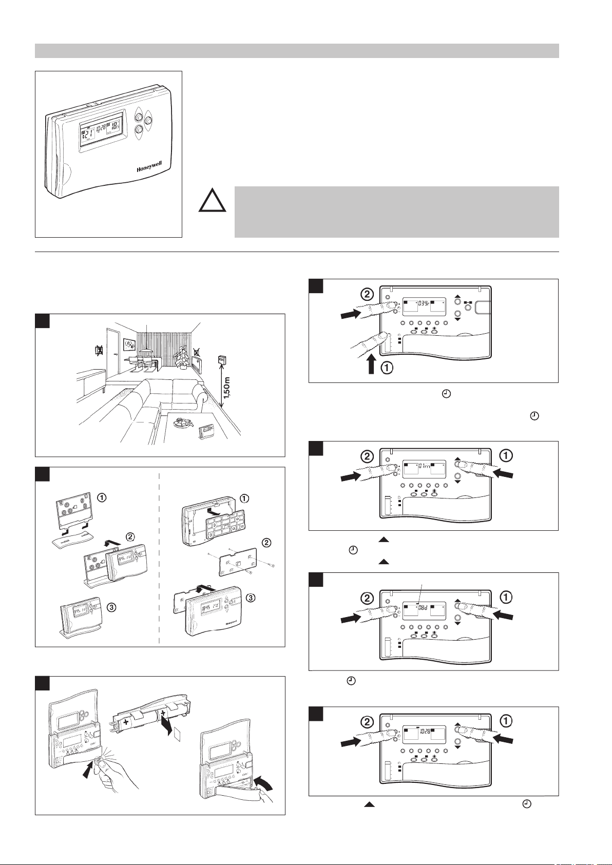
5: CM67z Room Unit
Positioning
The CM67z is a RF device and for the best performance
should be installed in an open space. Leave at least 30cm
distance from any metal objects including wall boxes.
Caution!
!
When selecting the operating site ensure that the distance to wireless devices
such as wireless headphones, cordless phones etc. is approx. 1-2m accord-
ing to the DECT standard or within 1m of other electrical devices
.
Do not mount the CM67z on metal surfaces or wall boxes.
Remove the insulation tab from the CM67z battery compartment.
The CM67z Room Unit provides a central point from which to congure the system and set
the time and temperature proles for each Zone. At a given time, as dened within a Zone
prole, the CM67z Room Unit transmits the required temperature setpoint to the respective
HR80UK Radiator Controllers, local temperature control and override is then provided at
each HR80UK Radiator Controller.
In the default setting, the CM67z Room Unit on-board sensor is disabled allowing it to be
moved around, however, this may be enabled for certain applications as described within
Section 8: Changing the conguration
For normal operation refer to the CM Zone User Guide
MON TUE WED THU FRI
SAT SUN
Setting the clock
Move the CM67z slider to DATE/ position. When setting the
date and time for the rst time after batteries were inserted the
zone controller display will ash as shown. Press the + or
-
buttons to set the current year (e.g. 03 = 2003).
Press the TEMP
button to go to the month:
Press the + or
-
to set the current month (e.g. 01 = January).
Press the TEMP
button to go to the day of the month:
Press the + or
-
to set the current day of the month. Check if the
day marker on the display indicates the correct day of the week.
Press TEMP
button to go to the time: Press the + or
-
until the correct time is displayed. Holding the button for a few
seconds will change the time slowly then quickly.
TEMP
DATE/
PROG
PROG
AUTO
OFF
z1
z2
MAN
z1
MAN
z2
1 2 3 4 5 6
PROG
COPY
DAY
DAY 1...7
z1
z2
z2
z1
MON TUE WED THU FRI SAT SUN
TEMP
DATE/
PROG
PROG
AUTO
OFF
z1
z2
MAN
z1
MAN
z2
1 2 3 4 5 6
PROG
COPY
DAY
DAY 1...7
z1
z2
Day of the week indicator
z2
z1
MON TUE WED THU FRI SAT SUN
TEMP
DATE/
PROG
PROG
AUTO
OFF
z1
z2
MAN
z1
MAN
z2
1 2 3 4 5 6
PROG
COPY
DAY
DAY 1...7
z1
z2
AM PM
z1
z2
MON TUE WED THU FRI SAT SUN
TEMP
DATE/
PROG
PROG
AUTO
OFF
z1
z2
MAN
z1
MAN
z2
1 2 3 4 5 6
PROG
COPY
DAY
DAY 1...7
z1
z2
z2
z1
MON TUE WED THU FRI SAT SUN
CM67z Room Unit
Wall MountingTable Stand
1
2
3
7
6
5
4
Start up
 Loading...