


XL 800 Series
FOR SMOKE CONTROL
HONEYWELL EXCEL 5000 OPEN SYSTEM
CONTENTS |
|
General ............................................................................... |
3 |
Before Installation ............................................................. |
3 |
Installation ......................................................................... |
3 |
Wiring ................................................................................. |
4 |
XL800 Series Power Consumption ................................ |
5 |
I/O Modules ................................................................... |
5 |
Description of the XCL8010AU Controller Module ......... |
7 |
Overview........................................................................ |
7 |
Interfaces and Bus Connections .................................. |
10 |
Technical Data............................................................. |
10 |
System Data........................................................... |
10 |
Operational Environment ....................................... |
10 |
Smoke Control Configuration....................................... |
10 |
Data File Set-Up .......................................................... |
11 |
Panel Reset ................................................................. |
11 |
Typical Power Limited Circuit for XL800 ...................... |
11 |
Connecting Single Bus Controller Systems ................. |
11 |
XCL8010AU, I/O Modules on Single Rail............... |
12 |
Multiple Rails in Single Cabinet.............................. |
12 |
LonWorks Bus I/O Modules in Separate Rooms .... |
12 |
How to Connect Panel Bus and LONWORKS Bus Mixed |
|
Controller Systems ...................................................... |
12 |
Connecting I/O Modules......................................... |
12 |
Connecting I/O Modules to the XCL8010AU.......... |
12 |
Setting Address of Panel Bus I/O Modules.................. |
13 |
Setting the I/O Bus Switch ........................................... |
14 |
LONWORKS Bus Topologies.......................................... |
14 |
C-Bus Topologies ........................................................ |
14 |
Mounting/Dismounting Modules.................................... |
14 |
Mounting/Dismounting Controller/Sockets ................... |
15 |
Mounting Sockets................................................... |
15 |
Connecting Sockets ............................................... |
15 |
Dismounting Sockets ............................................. |
16 |
Mounting/Dismounting Electronic Modules .................. |
16 |
Mounting Electronic Modules ................................. |
16 |
Dismounting Electronic Modules ............................ |
17 |
Connecting via C-Bus .................................................. |
17 |
Connecting to the Controller................................... |
17 |
Setting the C-Bus Termination Switch.................... |
17 |
Shielding ................................................................ |
17 |
INSTALLATION AND COMMISSIONING INSTRUCTIONS
Connecting HMIs or Laptops........................................ |
17 |
Connecting the XI582 Operator Interface ............... |
17 |
Connecting Laptops (XL-Online/CARE) ................. |
18 |
XCL8010AU Terminals........................................... |
18 |
Features....................................................................... |
18 |
LONWORKS Interface and Terminals ....................... |
18 |
LONWORKS Service LED and Button....................... |
18 |
C-Bus Tx LED and Rx LED .................................... |
19 |
Reset Button........................................................... |
19 |
HMI Interface.......................................................... |
19 |
Alarm and Power LEDs .......................................... |
20 |
Watchdog Status .................................................... |
20 |
Modem Interface..................................................... |
20 |
I/O Bus Switch S2................................................... |
20 |
C-Bus Termination Switch S1................................. |
21 |
Memory .................................................................. |
21 |
Description of the I/O Modules ....................................... |
21 |
Common Features ....................................................... |
21 |
Analog Input Modules .................................................. |
22 |
Types of Analog Input Modules .............................. |
22 |
Features ................................................................. |
22 |
Terminals................................................................ |
22 |
XFL821AU Connection Examples .......................... |
23 |
Analog Output Modules................................................ |
24 |
Types of Analog Output Modules ........................... |
24 |
Features ................................................................. |
24 |
Terminals................................................................ |
24 |
Technical Data........................................................ |
24 |
Modules with Manual Overrides ............................. |
25 |
XFL822AU Connection Example ............................ |
25 |
Synchronization Behavior of Analog Output Module |
|
Configured as Floating Output................................ |
25 |
Binary Input Modules ................................................... |
26 |
Types of Binary Input Modules ............................... |
26 |
Features ................................................................. |
26 |
Terminals................................................................ |
26 |
Technical Data........................................................ |
26 |
Status LEDs............................................................ |
27 |
XF823AU Connection Examples ............................ |
27 |
Relay Output Modules.................................................. |
28 |
Types of Relay Output Modules ............................. |
28 |
Features ................................................................. |
28 |
Terminals................................................................ |
28 |
Permissible Loads .................................................. |
29 |
Status LEDs with Manual Overrides ....................... |
29 |
Connection Examples............................................. |
30 |
Copyright © 2008 Honeywell GmbH All Rights Reserved |
EN1B-0410GE51 R0908A |

General |
Excel 800 |
Troubleshooting............................................................... |
31 |
Testing Wiring Connections.......................................... |
31 |
Troubleshooting on the XCL8010AU Controller............ |
31 |
Power LED (green) ................................................. |
31 |
Alarm LED (red) ...................................................... |
32 |
LONWORKS Service LED.......................................... |
32 |
C-Bus Tx and Rx LEDs........................................... |
33 |
HMI Tx and Rx LEDs .............................................. |
33 |
I/O Modules Troubleshooting........................................ |
34 |
Power LED of I/O Modules ..................................... |
34 |
Service LED of I/O Modules.................................... |
35 |
Trademark Information
Echelon, LON, LONMARK, LONTALK, LONWORKS, Neuron, are trademarks of Echelon Corporation registered in the United States and other countries.
EN1B-0410GE51 R0908A |
2 |
Excel 800
 WARNING
This equipment generates, uses, and can radiate radio frequency energy, and if not installed and used in accordance with the instructions manual, may cause interference to radio communications. It has been tested and found to comply with the limits for a Class A computing device pursuant to Subpart J of Part 15 of FCC Rules, which are designed to provide reasonable protection against such interference when operated in a commercial environment. Operation of this equipment in a residential area is likely to cause interference, in which case the user, at his own expense, will be required to take whatever measures may be required to correct the interference. Any unauthorized modification of this equipment may result in the revocation of the owner’s authority to continue its operation.
General
The XL800 Series is designed to provide heating, ventilating and air-conditioning control. They can operate either standalone, or networked to Honeywell central workstations such as EBI. These controllers can also be used for smoke control system monitoring and control, for monitor and control of fire (UL864), and general purpose signaling (UL2017). In UL 2017 applications, the product can be used as a type NM (Non-Monitored) system. It is also approved for UL916 (Energy Management Equipment.)
The XL800 Series can be used for smoke control applications when used in conjunction with a UL listed fire alarm control panel (FACP) and UL listed fire fighters’ smoke control station (FSCS).
Before Installation
1.Unpack door and remove the XL800 from carton. Check equipment and report any damage to a Honeywell representative.
2.Verify cabinet is installed correctly.
3.Securely mount the XL800 to a rigid structural surface using at least four sets of 1/4 in. (6 mm) mounting hardware (supplied locally).
NOTE: Anchoring materials must be suitable for the mounting surface (wood, concrete, steel). Mounting must comply with all local codes.
4.Obtain correct number and type of sheet metal screws for subpanel. Installation of a full-size subpanel requires six no. 10 x ½-inch (13 mm) sheet metal screws (not supplied). Installation of a smaller subpanel requires four no. 10 x ½-inch (13 mm) sheet metal screws (not supplied).
5.Obtain 14505159-001 Tamper Switch per job requirements. Installation of Tamper Switch is optional.
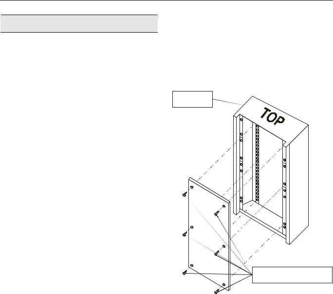
Installation
Mount controller subpanel in cabinet so all labeling is visible. Secure full-size subpanel in place with six no. 10 x ½-inch (13 mm) sheet metal screws (not supplied). Secure smaller subpanel with four no. 10 x ½-inch (13 mm) sheet metal screws (not supplied).
NOTE: Subpanel must mount flat and should not bulge or recess anywhere.
FULL-SIZE
CABINET
SIX NO. 10 x ½-INCH (13 mm)
SHEET METAL SCREWS
Fig. 1. Mounting controller subpanel in cabinet (full-size subpanel cabinet shown)
3 |
EN1B-0410GE51 R0908A |
Wiring |
Excel 800 |
Wiring
All wiring to the XL800 controller is unsupervised, except as noted.
All circuits are power limited, except for AC power circuits, relay contacts and other circuits as noted.
All field wiring terminals accept 24 AWG to 14 AWG (0.25 mm2 to 2 mm2) conductors except as noted.
All wiring must conform to local codes, ordinances, and regulations. Refer to job drawings for details.
Verify that the voltage difference between any conductor and earth ground does NOT exceed 150 Vac.
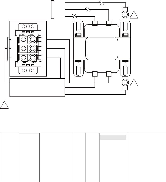
1.Connect input/output device wiring, C-Bus transmission wiring (minimum 18 gage [0.8012 sq mm]), LON Bus transmission wiring, and 14507063 Power Cable to Controller per job drawings. Fig. 2 and Fig. 3 show typical controller wiring. Four Power Module models are available (see Table 2).
2.Connect line voltage to Terminals H and N of the 14507287 Power Module. Connect a good earth ground to Terminal G of the Power Module. Fig. 5 through Fig. 7 show typical power wiring.
3.For Power Modules -001 through -007, leave power to Power Supply and Controller OFF. Connect 14507063 Power Cable from Controller to Power Module.
 WARNING
Risk of electric shock or equipment damage!
►Subpanel and Controller power must remain OFF until Controller is checked.
4.Install optional Tamper Switch on cabinet per instructions in the cabinet installation instructions. Wire Tamper Switch per job drawings.
5.Mount cabinet door.
CAUTION
Risk of electric equipment damage! Excessive static can burn out equipment.
►Observe proper anti-static material handling practices when installing or servicing PC parts and related components.
►Observe proper equipment and body grounding practices.
►Discharge static electricity from your body before handling parts.
|
|
Table 1. Connector terminal specifications |
||||
connector terminal |
pin |
signal type |
input / |
voltage |
max. |
max. current |
|
|
|
output |
type |
voltage |
|
analog input |
AI |
input |
SIGNAL |
±12 V |
±20 mA |
digital input |
DI |
input |
SIGNAL |
±10 V |
±20 mA |
|
|
|
|
|
|
analog output |
AO |
output(1 |
SIGNAL |
±10 V |
±20 mA |
digital output |
DO |
output(2 |
AC/DC |
±24 VAC/DC |
±50 mA |
totalizer output |
TI |
input |
SIGNAL |
±12 V |
±12 mA |
signal ground |
GND |
-- |
-- |
-- |
-- |
J1 RS-485 (C-BUS) (3 1 |
+A |
input / output |
SIGNAL |
±5 V |
1 mA / 180 mA |
2 |
-A |
input / output |
SIGNAL |
±5 V |
1 mA / 180 mA |
|
|
|
|
|
|
3S |
Shield A |
-- |
-- |
-- |
-- |
(1 special application; (2 regulated; (3 supervised
max. |
max. line |
frequency |
impedance |
9600 baud |
8K ohms |
--15K ohms
9600 baud 8K ohms
--10K ohms
100 Hz
----
9600 baud |
100 ohms |
9600 baud |
100 ohms |
----
Table 2. Power module models
|
model |
|
transformer max. input |
|
(48 VA) controller |
|
accessory output |
|
convenience outlet |
||||
|
|
|
|
||||||||||
|
|
Vac |
current draw |
Hz |
|
VAC output |
|
|
|||||
|
|
|
|
|
|
|
|
|
|
||||
14507287-001 |
120 |
0.5 A |
60 |
24 |
|
|
|
|
|
120 Vac, 10A |
|||
14507287-002 |
120 |
1.7 A |
60 |
24 |
24 |
Vac, 100 |
VA, 24 |
Vac, 40 VA |
|
120 Vac, 10A |
|||
14507287-003 |
120 |
1.7 A |
60 |
24 |
24 |
Vac, 100 |
VA, 24 |
Vdc, 600 mA |
|
120 Vac, 10A |
|||
|
|
|
|
|
|
|
|
|
|
||||
14507287-007 |
120 |
120 A |
60 |
24 |
-- |
|
|
|
-- |
||||
|
|
|
|
|
|
|
|
|
|
|
|
|
|
EN1B-0410GE51 R0908A |
4 |

Excel 800 |
|
Wiring |
XL800 Series Power Consumption |
|
I/O Modules |
When selecting the appropriate power supply, the power consumption of the XL800 modules must be taken into account.
Table 3. XL800 power consumption
|
max. power consumption |
|
model |
24 Vac, 60 Hz |
24 Vdc |
XCL8010AU with |
690 mA |
640 mA |
watchdog load |
|
|
XCL8010AU without |
190 mA |
140 mA |
watchdog load |
|
|
XF821AU, XFL821AU |
130 mA |
80 mA |
|
|
|
XF822AU, XFR822AU, |
160 mA |
90 mA |
XFL822AU, XFLR822AU |
|
|
XF823AU, XFL823AU |
180 mA |
130 mA |
XF824AU, XFR824AU, |
140 mA |
90 mA |
XFL824AU, XFLR824AU |
|
|
XFR825AU |
140 mA |
90 mA |
Variants of I/O Modules
There are two variants of I/O modules:
•Panel Bus I/O modules with communication via Panel Bus (light-gray housings)
Modules are automatically commissioned (with firmware download) by the XCL8010AU
•LONWORKS Bus I/O modules (dark-gray housings) with
communication via LONWORKS (FTT10-A, link power compatible) for easy integration and use with 3rd-party controllers
Terminal Sockets
I/O modules are mounted on the appropriate terminal sockets. Panel Bus I/O modules and LONWORKS Bus I/O modules use the same terminal sockets.
Color Coding
To distinguish modules and components, the following color coding is used:
Table 4. Color coding of Excel 800 Modules
|
color |
|
part |
|
|
||
|
red |
|
All of the user-accessible adjustable |
|
|
|
mechanical parts (i.e., bridge connectors and |
|
|
|
locking mechanism) and operating controls |
|
|
|
(manual overrides, etc.) |
|
|
|
|
|
light-gray |
|
Panel Bus I/O modules |
|
|
|
|
|
dark-gray |
|
LONWORKS Bus I/O modules |
|
|
|
|
5 |
EN1B-0410GE51 R0908A |
Wiring Excel 800
ANALOG |
ANALOG |
BINARY |
RELAY |
FLOATING |
INPUT |
OUTPUT |
INPUT |
OUTPUT |
OUTPUT |
LonWorks |
|
|
|
|
|
|
|
||
XFLR822AU |
|
|
XFLR824AU |
||||||
BUS |
|
|
|
|
|
|
|
||
MODULES |
|
|
|
|
|
|
|
||
|
|
|
|
|
|
|
|
|
|
XFL821AU |
XFL822AU |
XFL823AU |
XFL824AU |
||||||
PANEL |
|
|
|
|
|
|
|
|
|
|
|
||||||
XFR822AU |
|
|
|
|
XFR824AU |
XFR825AU |
|||||||||||
BUS |
|
|
|
|
|
|
|
|
|
|
|
|
|
||||
MODULES |
|
|
|
|
|
|
|
|
|
|
|
|
|
||||
|
|
|
|
|
|
|
|
|
|
|
|
||||||
XF821AU |
XF822AU |
|
XF823AU |
XF824AU |
|||||||||||||
|
|
|
|
|
|
|
|
|
|
|
|
|
|
|
|
|
|
|
|
|
|
|
|
|
|
|
|
|
|
|
|
|
|
|
|
|
|
|
|
|
|
|
|
|
|
|
|
|
|
|
|
|
|
|
|
|
|
|
|
|
|
|
|
|
|
|
|
|
|
|
|
XCL8010AU |
XS821-22 |
|
|
XS823 |
|
XS824-25 |
|
|
|
||||
|
|
|
|
|
|
CONTROLLER MODULE |
|
LonWorks or Panel Bus |
|
|
|
|
|
|
Fig. 2. Overview of I/O modules and terminal sockets |
||
EN1B-0410GE51 R0908A |
6 |

Excel 800 |
Description of the XCL8010AU Controller Module |
Description of the XCL8010AU Controller Module
Overview
PC or HMI
EXCELON
I/O MODULES
|
|
NO CONNECTION |
|
LonWorks BUS |
|
C-BUS |
|
Fig. 3. Connections to the XCL8010AU Controller |
|||
|
Legend |
||
|
1 |
Power supply for I/O modules |
|
|
2 |
I/O Bus communication terminals |
|
|
3 |
LONWORKS interface |
|
|
4 |
LONWORKS service button |
|
|
5 |
LONWORKS service LED |
|
|
6 |
C-Bus Tx LED |
|
|
7 |
C-Bus Rx LED |
|
|
8 |
Reset button |
|
|
9 |
HMI interface (for field use, only) |
|
|
10 |
Alarm LED |
|
|
11 |
Power LED |
|
|
12 |
Power supply terminals |
|
|
13 |
Alarm/watchdog outputs |
|
|
14 |
NO CONNECTION |
|
Fig. 4. XCL8010AU Controller Module front details |
15 |
S2 I/O Bus switch |
|
16 |
S1 C-Bus termination switch |
||
|
|||
|
17 |
C-Bus terminals |
|
|
18 |
LONWORKS terminals |
|
7 |
EN1B-0410GE51 R0908A |
Description of the XCL8010AU Controller Module |
Excel 800 |
24 VAC CONTROLLER POWER SWITCH
MAIN LINE VOLTAGE 120 VAC, 60 HZ TERMINAL “G“ MUST BE
CONNECTED TO A GOOD EARTH GROUND.
|
|
14507063-002 POWER CABLE |
||
|
(incl. with 14507287 power modules |
|||
|
14507287-001 through -003, only.) |
|||
CONNECTOR TO |
|
|
BRN |
|
|
|
GRN |
|
|
XL800 CONTROLLER |
|
|||
|
BLK |
|
||
J5 |
|
|
||
|
|
CONNECTORS ARE KEYED TO |
||
|
|
PREVENT MISALIGNMENT. |
||
|
|
CONVENIENCE OUTLET |
||
|
|
(UNFILTERED, UNSWITCHED) |
||
|
|
|
-001 = 120 VAC, 10 AMP |
|
120 VAC, 60 HZ |
|
|
|
|
|
|
|
|
|
|
|
|
||
|
LINE INPUT |
|
|
|
|
|
|
|
|
|
|
|
|
|
|
|
|
|
|
|
|
|
|
|
|
|
|
|
|
|
|
|
|
|
|
|
|
|
|
2 AMP |
|
|
FUSE F1 (2 AMPS) PART NUMBERS ARE AS FOLLOWS: |
|
|
|
|
CONTROLLER |
|
|
–HONEYWELL PART NO. 14000485-007 |
||||||||
|
|
|
F1 |
|||||||||||
|
|
* |
|
|
POWER |
|
|
(AVAILABLE FROM HONEYWELL BRANCH LOCATIONS, ONLY) |
||||||
|
|
|
|
|
|
|
–BUSSMAN PART NO. AGC-2 |
|||||||
|
|
|
|
|||||||||||
|
|
H |
ON |
|
|
|
|
|
–LITTLEFUSE PART NO. 312002 |
|||||
|
|
N |
OFF |
|
|
|
|
|
|
|
||||
|
|
G |
|
|
|
|
|
|
|
|||||
|
|
CONTROLLER |
|
|
|
|
|
|||||||
|
|
|
|
|
|
|
|
|||||||
|
|
|
|
|
|
|
|
|||||||
|
|
|
SUPPLY |
|
|
|
|
|
|
|
||||
|
|
|
24VAC |
|
|
|
|
|
|
|
||||
|
|
|
48VA ~ |
|
|
|
|
|
|
|
||||
|
|
|
|
MUST BE WIRED |
|
|||||||||
|
|
|
G |
|
|
|||||||||
|
|
|
|
TO EARTH GROUND |
|
|||||||||
|
|
|
|
|
|
|
|
|
|
|||||
|
|
|
|
|
|
|
|
|
|
|
|
|
|
|
“G“ MUST BE |
|
|
|
|
|
UNSWITCHED |
|
|
||||||
WIRED TO EARTH GROUND |
|
|
||||||||||||
|
|
|
|
|
|
|
|
UNFILTERED |
|
|
||||
120VAC
*14507287-001 POWER TERMINALS LABELED H-N-G.
Fig. 5. Typical 14507287-001 Power Module wiring
24 VAC CONTROLLER POWER SWITCH
MAIN LINE VOLTAGE 120 VAC, 60 HZ TERMINAL “G“ MUST BE
CONNECTED TO A GOOD EARTH GROUND.
|
|
14507063-002 POWER CABLE |
||
|
(incl. with 14507287 power modules |
|||
|
14507287-001 through -003, only.) |
|||
CONNECTOR TO |
|
|
BRN |
|
|
|
GRN |
|
|
XL800 CONTROLLER |
|
|||
|
BLK |
|
||
J5 |
|
|
||
|
|
CONNECTORS ARE KEYED TO |
||
|
|
PREVENT MISALIGNMENT. |
||
|
|
CONVENIENCE OUTLET |
||
|
|
(UNFILTERED, UNSWITCHED) |
||
|
|
|
-002 AND -003 = 10 AMP |
|
120 VAC, 60 HZ LINE INPUT
|
|
CONTROLLER |
2 AMP |
|
|
5 AMP |
|
|
|
|
|
|
|
||||||
|
|
F1 |
|
F2 |
|
||||
|
* |
POWER |
|
|
|
|
|||
|
H |
ON |
|
|
|
ON |
|
|
|
|
N |
OFF |
|
|
|
OFF |
|
|
~ |
|
G |
|
|
|
2 AMP |
||||
|
|
|
|
|
|
|
|||
|
|
CONTROLLER |
|
|
|
F3 |
|
|
|
|
|
|
|
|
|
|
|
||
|
|
SUPPLY |
MUST BE WIRED |
|
|
|
|||
|
|
24VAC |
TO EARTH GROUND |
|
|
|
|||
48VA ~
G
120 VAC, 60 HZ LINE INPUT
24VAC ACCESSORY POWER -002 AND -003 MODELS (4 AMP MAX.)
|
24 VAC ACCESSORY POWER |
|
|
|
|
“G“ MUST BE |
-002 MODEL, ONLY. 2 AMP MAX. |
|
|
|
|
WIRED TO EARTH GROUND |
|
|
|
|
|
|
FOR 14507287-003 (24VDC) |
BRN |
GRY |
BRN |
GRY |
|
FOR 14507287-002 (24VAC) |
RED |
BRN |
GRY |
GRY |
|
UNSWITCHED |
|
|
|
|
|
UNFILTERED 120 VAC |
|
|
|
|
* 14507287-001 POWER TERMINALS LABELED H-N-G.
POWER MODULE |
FUSE NO. |
FUSE RATING |
HONEYWELL PART NO. |
BUSSMAN PART NO. |
LITTLEFUSE PART NO. |
14507287-001 THROUGH -003 |
F1 |
2 AMPS |
14000485-007 |
AGC-2 |
312002 |
14507287-002 AND -003 |
F2 |
5 AMPS |
14507374-001 |
GMA 5AMP |
235005 |
14507287-002 AND -003 |
F3 |
2 AMPS |
14000485-007 |
AGC-2 |
312002 |
Fig. 6. Typical 14507287-002, -003 Power Module wiring
EN1B-0410GE51 R0908A |
8 |
Excel 800 |
Description of the XCL8010AU Controller Module |
CONTROLLER TRANSFORMER
|
|
|
|
|
|
|
|
|
|
|
|
|
|
|
|
|
GRN |
|
||
|
CONTROLLER |
G |
|
70 |
|
|
|
|
|
|||||||||||
|
|
|
|
|
BRN |
|
||||||||||||||
SUPPLY 24 VAC |
~ |
|
|
|
|
|
|
|
||||||||||||
|
|
71 |
|
|
|
|
||||||||||||||
|
|
|
|
|
|
48 VA |
|
|
|
BLK |
|
|
|
|
|
|||||
|
|
|
|
|
|
|
|
|
|
|
|
|
|
|
|
|
|
|||
|
|
|
|
|
|
|
|
|
|
|
|
72 |
|
|
|
|
|
|
||
|
|
|
|
|
|
|
|
|
|
|
|
|
3 |
4 |
|
|
|
|||
|
|
|
|
|
|
|
|
|
|
|
|
|
|
|
|
|||||
|
|
|
|
|
|
|
|
|
|
|
|
|
|
|
|
|
||||
|
|
|
|
|
|
|
|
|
|
|
|
|
|
|
|
|
|
|
|
|
|
|
|
|
|
|
|
|
|
|
|
|
|
|
|
|
|
|
|
|
|
|
|
|
|
|
|
|
|
|
|
|
|
|
|
|
|
|
|
|
|
|
|
|
|
|
|
|
|
|
|
|
|
|
|
|
|
|
|
|
|
|
|
|
|
|
|
|
|
|
|
|
|
|
|
|
|
|
|
|
|
BLK |
|
|
|
|
|
|
|
|
|
|
|
|
|
|
|
|
|
|
|
|
|||
H |
|
|
|
|
|
|
|
|
|
|
|
|
|
|
|
|
|
|
||
|
|
|
|
|
|
|
|
|
|
|
|
|
|
|
|
WHT |
|
|||
|
|
|
|
|
|
|
|
|
|
|
|
|
|
|
|
|
|
|
||
|
|
|
|
|
|
|
|
|
|
|
|
|
|
|
|
|
|
|
||
|
|
|
|
|
|
|
|
|
|
|
|
|
|
|
|
|
|
|
||
|
|
|
|
|
|
|
|
|
|
|
|
|
|
|
|
|
|
|||
N |
|
|
|
|
|
|
|
|
|
|
|
|
|
|
|
|
|
|
||
|
|
|
|
|
|
|
|
|
|
|
|
|
|
|
|
GRN |
|
|||
|
|
|
|
|
|
|
|
|
|
|
|
|
|
|
|
|
|
|
||
|
|
|
|
|
|
|
|
|
|
|
|
|
|
|
|
|
|
|
||
|
|
|
|
|
|
|
|
|
|
|
|
|
|
|
|
|
|
|
||
|
|
|
|
|
|
|
|
|
|
|
|
|
|
|
|
|
|
|||
G |
|
|
|
|
|
|
|
|
|
|
|
|
|
|
|
|
|
|
||
|
|
|
|
|
|
|
|
|
|
|
|
|
|
|
|
|
|
|
||
|
|
|
|
|
|
|
|
|
|
|
|
|
|
|
|
|
|
|
|
|
|
|
|
|
|
|
|
|
|
|
|
|
|
|
|
|
|
|
|
|
|
|
|
|
|
|
|
|
|
|
|
|
|
|
|
|
|
|
|
|
|
|
|
|
|
|
|
|
|
|
|
|
|
|
|
|
|
|
|
|
|
|
|
MAIN LINE (120 VAC, 60 Hz)
TERMINAL “G” MUST BE
CONNECTED TO A GOOD
EARTH GROUND.
24 V 50 VA
14507351-001 429P156A E1A 1052 XXXX
COM 120 V
1 2
1
1
1 MECHANICALLY SECURED TO SUBPANEL WITH MOUNTING SCREW
Fig. 7. Typical 14507287-007 Power Module wiring
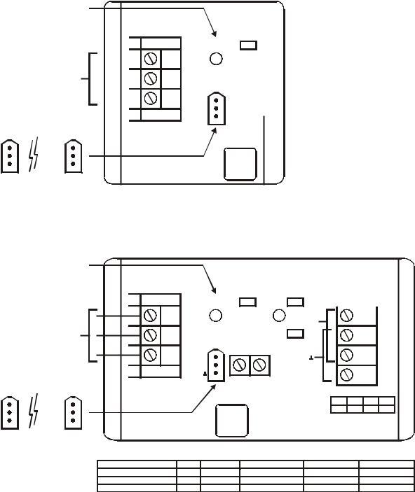
I/O Module Overview
Table 5. Overview of I/O modules
Panel Bus |
LONWORKS |
description |
inputs |
outputs |
manual controls |
LEDs 1) |
module |
Bus module |
|
|
|
|
|
XF821AU |
XFL821AU |
Analog Input Module |
8 |
– |
– |
– |
|
|
|
|
|
|
|
XF822AU |
XFL822AU |
Analog Output Module |
– |
8 |
– |
8 status LEDs |
|
|
|
|
|
|
|
XFR822AU |
XFLR822AU |
Analog Output Module |
– |
8 |
8 manual overrides |
8 status LEDs |
|
|
|
|
|
|
|
XF823AU |
XFL823AU |
Binary Input Module |
12 |
– |
– |
12 status LEDs |
|
|
|
|
|
|
|
XF824AU |
XFL824AU |
Relay Output Module |
– |
6 2) |
– |
6 status LEDs |
XFR824AU |
XFLR824AU |
Relay Output Module |
– |
6 2) |
6 manual overrides |
6 status LEDs |
XFR825AU |
– |
Floating Output Module |
– |
3 |
3 manual overrides |
3 pairs of status LEDs |
1)In addition to the power LED and service LED
2)Changeover outputs
9 |
EN1B-0410GE51 R0908A |
Description of the XCL8010AU Controller Module |
Excel 800 |
Corresponding Terminal Sockets
Table 6. I/O modules and corresponding terminal sockets
|
I/O module |
|
|
socket |
|
|
scope of delivery |
|
|
|
|
|
|
|
|||
|
XF821AU, |
|
|
|
|
1 terminal socket, |
||
|
XFL821AU |
|
|
|
|
1 bridge connector |
||
|
|
|
|
|
|
|
1 swivel label holder |
|
|
XF822AU, |
|
XS821-22 |
|
||||
|
|
|
|
|
||||
|
XFL822AU, |
|
|
|
|
|
|
|
|
XFLR822AU, |
|
|
|
|
|
|
|
|
XFR822AU |
|
|
|
|
|
|
|
|
|
|
|
|
|
|
|
|
|
XF823AU, |
|
|
|
|
1 terminal socket, |
||
|
|
XS823 |
|
1 bridge connector |
||||
|
XFL823AU |
|
|
|||||
|
|
|
|
|
1 swivel label holder |
|||
|
|
|
|
|
|
|
||
|
|
|
|
|
|
|
||
|
XF824AU, |
|
|
|
|
1 terminal socket, |
||
|
XFL824AU, |
|
|
|
|
1 bridge connector |
||
|
XFLR824AU, |
|
XS824-25 |
|
1 swivel label holder |
|||
|
XFR824AU |
|
|
|
|
1 long cross connector |
||
|
XFR825AU |
|
|
|
|
|
|
|
|
|
|
|
|
|
|
|
|
Interfaces and Bus Connections
The Excel 800 System can be connected to the following devices and systems:
Panel Bus
•For communication with up to 16 Panel Bus I/O modules
•Polarity-insensitive
LonWorks Bus
•For communication with other LONWORKS Bus devices within the building
•FTT10, link power compatible
•Polarity-insensitive
C-Bus
• For communication with other controllers
HMI
•For connecting an operator interface, e.g., XI582 or a laptop, e.g., for CARE
Modem
• NO CONNECTION
Technical Data
System Data
Table 7. System data
Operating voltage |
24 VAC/DC, 60 Hz |
|
Max. 3.57 A |
Power consumption |
|
|
(1 XCL8010AU Controller |
|
+ 16 I/O modules) |
|
|
Operational Environment
Table 8. Operational environment
ambient operating |
0 |
─ 49 °C (32 ─ 122 °F) |
temperature |
|
|
ambient operating |
5 |
─ 93 % rel. humidity |
humidity |
(non-condensing) |
|
ambient storage |
–20 ─ +70 °C (–4 ─ +158 °F) |
|
temperature |
|
|
ambient storage |
5 |
─ 95 % rel. humidity |
humidity |
(non-condensing) |
|
|
|
|
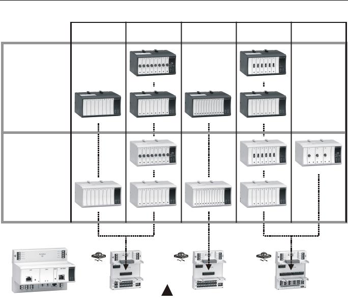
Smoke Control Configuration
|
|
SMOKE CONTROL CONFIGURATION |
|
|
|
|
|||||||||||
|
|
|
XL800 |
|
|
|
|
|
9 |
|
|
||||||
|
|
|
|
|
|
|
|
|
|
|
|
|
|
|
|
|
|
|
|
|
|
|
|
|
|
|
|
AO |
|
|
SUPPLY |
|
4 |
||
|
|
|
|
|
|
|
|
11 |
|
|
|
|
|
FAN |
|
||
UL-LISTED |
8 |
|
|
|
|
|
|
|
|
|
|
|
AIRFLOW SENSOR |
||||
|
|
|
|
|
|
|
|
|
|
|
|||||||
FIRE ALARM |
|
|
|
|
|
|
|
|
|
|
|
|
|
|
|
||
|
|
|
|
|
|
|
AO |
|
|
EXHAUST |
5 |
||||||
CONTROL UNIT |
|
|
|
|
|
|
|
|
|
||||||||
|
|
|
|
|
|
||||||||||||
|
|
|
|
|
|
|
|
12 |
|
|
|
|
|
FAN |
|
||
|
|
|
|
|
|
|
|
|
|
|
|
|
|
|
|
|
|
|
|
|
|
|
|
|
|
|
|
|
|
|
|
|
|
||
FIREFIGHTERS’ |
|
|
2 |
|
AO |
|
|
|
|
DAMPER 3 |
|||||||
SMOKE CONTROL |
|
|
|
|
|
|
|
|
|
||||||||
PANEL (FSCS) |
|
|
|
|
|
|
|
|
VERIFICATION |
|
|||||||
14505068 |
|
|
|
|
|
|
|
|
|
|
|
|
|
|
|||
|
|
|
|
|
|
|
|
|
|
|
|
|
|
||||
AUDIBLE |
|
1 |
|
|
|
|
|
|
|
|
|
|
|
|
|
|
|
|
|
|
|
|
|
|
|
|
|
|
|
|
|
||||
ANNUNCIATOR |
|
|
|
|
|
|
|
|
|
|
|
|
|
|
|
||
|
|
|
|
|
|
|
|
|
|
|
|
10 |
|
6 |
7 |
||
|
|
|
|
|
|
STATUS CONTROL |
|
||||||||||
|
|
|
|
|
|
||||||||||||
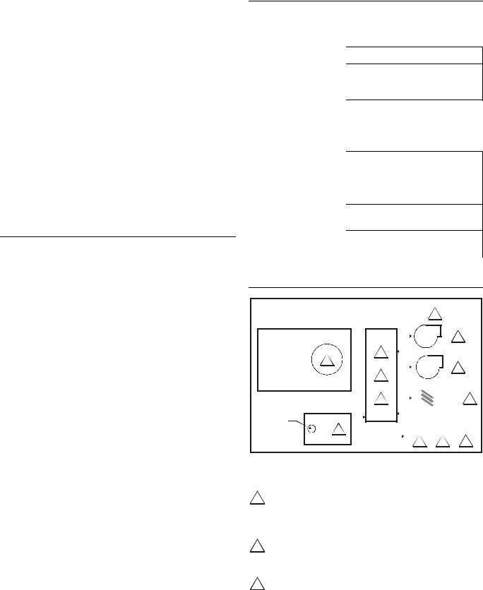
Fig. 8. Typical smoke control configuration
NOTES:
1Locate and configure per NFPA 92A, Section 3-4.3.4. UL-listed annunciator / FSCS panel switches have a minimum rating of 24 V, 1/10 Amp, and lamps / LEDs have a rating of 24 V, limited to 50 mA.
2Locate so as to minimize control wiring and piping. Avoid running wires or piping through areas that have a high fire risk.
3Locate per UL 555S.
EN1B-0410GE51 R0908A |
10 |
Excel 800 |
Description of the XCL8010AU Controller Module |
4Locate separate from and below all building exhaust fans and upstream of any prevailing winds.
5Exhaust to outside of building.
6Locate airflow differential switch.
7Locate UL-listed damper pressure / position indicator per damper installation instructions.
8Smoke control must be initiated by a listed fire alarm control unit or in zone automatic alarm devices and not devices located outside of the smoke control zone. Interconnecting wiring must be within 20 ft. (6 meters) and in conduit.
9Refer to NFPA 92A.
10Verify that the AC voltage source connected to the inside of the main line voltage terminal block is from a UL-1481 listed uninterruptible power supply. The main line voltage terminal block maximum current draw is 0.5 A. For 220/240 VAC (60 Hz) applications, verify that no potential between any conductor and the earth ground exceeds 150 VAC.
11All external LONWORKS bus field wiring must be limited to 4000 ft. (1200 meters) and be terminated to 14506944-001 transient protector (35 V, 290 mA max.) except C-Bus field wiring communicating at 1 MHZ, which uses 14502412-014 transient protector (19 V, 500 mA).
12Panel Bus wiring must be in the same enclosure or less than 20 ft. to adjacent enclosure. No protection is required.
Data File Set-Up
Generate the engineering data file for the XL800 Series Controllers. This data file has a mix of hardware points for the necessary inputs and outputs to control fans, dampers, and other equipment. In addition to the inputs and outputs, a custom control program is written to control the outputs per the sequence. The XL800 controllers can reset the program once the data from the operator interface indicates a normal condition for the dedicated smoke control equipment. Wire conditions must be programmed to provide annunciation of trouble conditions.
Also required for a dedicated application for the XL800, is a weekly time program to test control points, fans, and dampers by exercising the equipment and verifying feedback automatically during low building activity periods.
Panel Reset
When in Smoke Control Mode, panel reset is accomplished by resetting the initiating panel contact circuit or by the separate initiating/reset switch on the FSCS panel.
CAUTION
Risk of electric equipment damage!
►Failure to use listed/approved replacement parts can damage product, degrade operation and result in loss of safety function.
►This product must be installed and operated within its environmental, mechanical, and electrical specifications as contained in this document.
►When servicing, use only listed/approved replacement parts ordered directly from the manufacturer.
Typical Power Limited Circuit for XL800
POWER |
|
|
|
|
POWER |
|
|
|
|
|
|
|||||
LIMITED |
|
|
|
|
|
|
LIMITED |
|
|
|
|
|
|
|||
|
|
|
|
|
|
|
|
|
|
|
|
|
|
|
|
|
|
|
|
|
|
|
|
|
|
|
|
|
|
|
|
NON-POWER |
|
|
2 |
CPU |
ANALOG INPUT |
|
ANALOG OUTPUT |
DIGITAL INPUT |
DIGITAL OUTPUT |
|
LIMITED |
|||||||
|
|
|
|
|
||||||||||||
|
|
|
|
|
||||||||||||
|
|
MODULE |
|
|
MODULE |
MODULE |
MODULE |
|
|
|
||||||
|
|
|
|
|
|
|
|
|
|
|
|
|
|
|
|
|
|
|
|
|
|
|
|
|
|
|
|
POWER LIMITED |
|
|
|
|
|
|
|
|
|
|
|
|
|
|
|
|
|
24VAC |
|
|
|
|
|
|
|
|
|
CONTROL |
|
|
|
|
|
|
|
|
|||
|
|
|
|
|
24VAC |
ACCESSORY |
|
|
|
|
|
|||||
|
|
|
|
|
|
|
|
NON-POWER |
||||||||
|
|
|
|
|
|
|
|
|
|
24VAC |
|
|
|
|||
|
|
|
|
|
|
|
|
|
|
|
|
|
LIMITED |
|||
|
|
|
|
|
2 |
|
|
|
|
|
|
|
|
|
||
|
|
|
|
|
|
|
|
|
|
|
2 |
|
|
|
|
|
|
|
|
|
|
3 |
|
|
|
|
|
|
|
|
|
|
|
1 |
|
|
|
1 |
|
|
|
|
|
|||||||
|
|
|
|
|
|
|
|
|
||||||||
NON-POWER
LIMITED
NON-POWER
LIMITED
Fig. 9. Typical power-limited circuit for XL800
114507287-001 through -003 power module accessory 24 VAC output (rated 2A) must be wired in accordance with NFPA 70, Article 725 when routed within the cabinet or adjacent cabinets and also for external field wiring.
214507287-001, -002, -003, and -007 control power module 24 VAC output is inherently power-limited. Thus, all sourced power from the XL800 controller is power-limited. All field wiring from these controllers meet NFPA 70, Article 725 power limited Class II requirements.
3If a separate auxiliary power-limited 24 VAC power source is required, use a control power module (14507287-001 or -007 control supply).
4Devices must be installed in areas as shown. All cable must be routed as shown. All internal power-limited wiring must be separated by ¼ inch (6 mm) or barrier from non-power-limited wire. Excess wiring must be cut, trimmed, and dressed properly to ensure that proper clearances are maintained.
Connecting Single Bus Controller Systems
This section describes how to connect a controller system which uses Panel Bus I/O modules, only or LONWORKS Bus I/O modules, only.
11 |
EN1B-0410GE51 R0908A |
 Loading...