


V8043
Table of contents
 Loading...
INSTALLATION INSTRUCTIONS
Place Bar Code Here
95-6983-11
V4043, V4044 Valves;
V8043, V8044 Zone Valves
APPLICATION
These valves consist of an actuator motor and valve
assembly for controlling the flow of hot and/or cold water.
The V4043 and V8043 provide two-position, straight-
through control of supply water. The V4044 and V8044
provide two-position, diverting control of supply water.
The valves are designed for use with fan coil and other
units requiring quiet, compact water valves. The V8043E
and F also control supply water for baseboard radiators
and convectors. The V4043E and V8043J provide
straight-through control of steam only. Models are
available with 125 or 300 psi operating pressure.
INSTALLATION
When Installing this Product...
1. Read these instructions carefully. Failure to follow
them could damage the product or cause a hazard-
ous condition.
2. Check the ratings given in the instructions and on
the product to make sure the product is suitable for
your application.
3. Installer must be a trained, experienced service
technician.
4. After installation is complete, check out product
operation as provided in these instructions
CAUTION
1. Disconnect power supply before connecting
wiring to prevent electrical shock of equip-
ment damage.
2. Normally it is not necessary to remove the
powerhead from the valve body during instal-
lation. If the valve must be disassembled, be
certain that it is reassembled with the water
flow in the direction of the arrow. Reversal of
the powerhead will result in damage to the
gear train.
3. On 24V systems, never jumper the valve coil
terminals even temporarily. This may burn
out the heat anticipator in the thermostat.
IMPORTANT
Use this valve in hydronic heating systems
which do not contain dissolved oxygen in the
system water. The dissolved oxygen, which is
found in systems that have a frequent source of
makeup water, causes the rubber plug inside
the valve to deteriorate and eventually fail.
LOCATION
Install the valve in an area with adequate clearance to:
— Move the manual opening lever on the side of the
powerhead.
— Remove the powerhead cover.
— Wire the powerhead.
— Replace the powerhead motor.
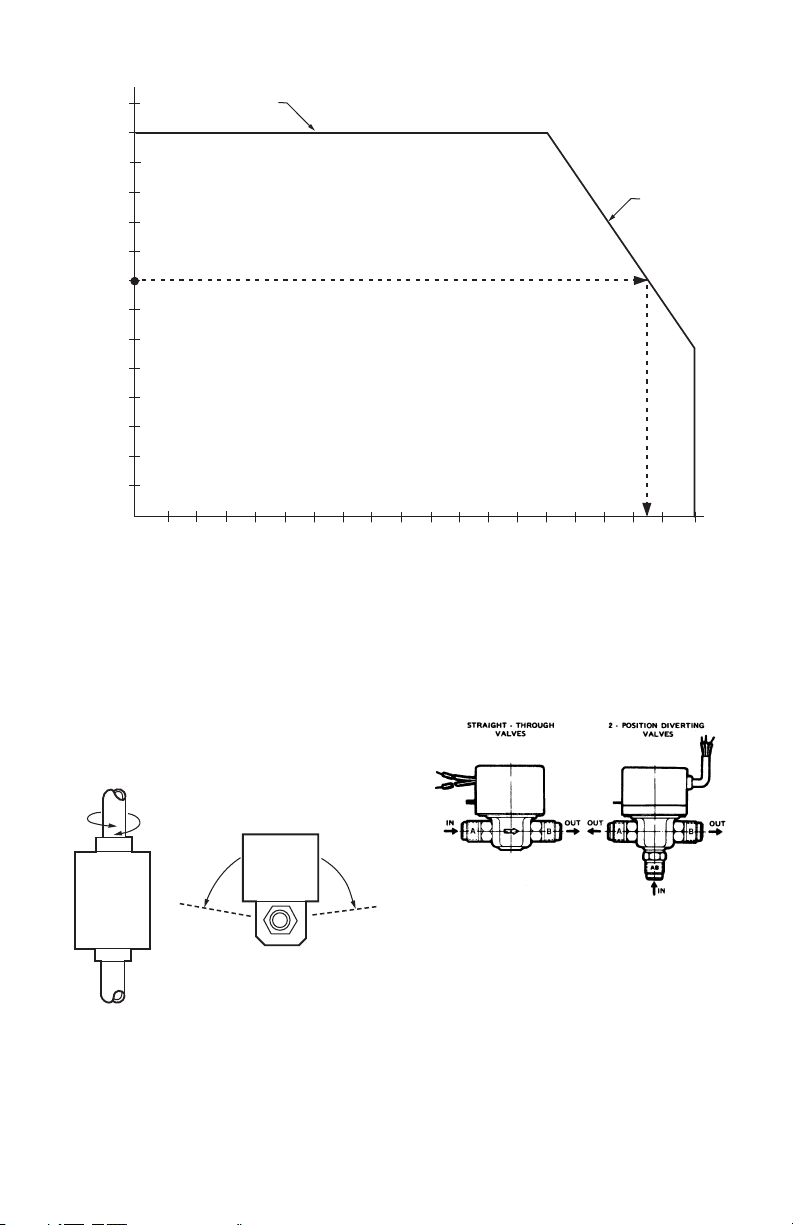
The valve location should be in an area where the
temperature does not exceed the maximum valve
operating temperature as shown in Fig. 1. The maximum
valve operating temperature depends on the maximum
ambient temperature at the valve location and the
maximum fluid temperature. Using the graph in Fig. 1,
the maximum valve operating temperature can be found
as follows:
1. Measure ambient temperature at valve and locate
this temperature on the ambient temperature scale
on the graph.
2. Draw a line from this ambient temperature, parallel
with the fluid temperature scale, to the maximum
fluid temperature line.
3. Draw a line from this point down to the fluid temp-
erature scale to find maximum operating tempera-
ture. (Note the example, shown by the dashed line
in Fig. 1).
V4043, V4044 VALVES; V8043, V8044 ZONE VALVES
95-6983—11 2
Fig. 1. Maximum temperature characteristics of valves.
MOUNTING
The valve can be mounted in any position on a vertical
line. If the valve is mounted horizontally; the powerhead
must be even with or above the center line of the piping.
Make sure that enough room is provided above the
powerhead to remove the cover for servicing.
Fig. 2. Mounting positions.
Mount the valve directly in the tube or pipe. Make sure
that the flow through the valve is in the direction indicated
by the arrow stamped on the valve body.
On diverting valves, the three fittings or ports are labeled
on the bottom of the valve body casting. See Fig. 3. Port
AB is the inlet port and is open at all times. Port A is
closed when the valve is de-energized; port B is open
when the valve is de-energized. Refer to the equipment
manufacturer’s instructions to determine which port (A or
B) should be connected to the coil bypass.
Fig. 3. Inlet and outlet ports on straight-through and
diverting valves.
FLARE FITTING MODELS
Use new, properly reamed pipe, free from chips. The
valve body is threaded for standard 5/8 in. OD copper, 45
degree SAE flare fitting nuts. These nuts are not furnished
with the valve and must be obtained separately.
SWEAT COPPER MODELS
1. Use new, properly reamed pipe, free from dents or
corrosion.
2. Place the valve onto the pipe. Set the manual open-
ing lever to MAN. OPEN position before applying
heat. This protects the plug inside the valve by
removing it from the seat.
EXAMPLE: 150°F (66°C) IS THE AMBIENT TEMPERATURE AT THE VALVE,
235F (113C) IS MAXIMUM FLUID TEMPERATURE.
MAXIMUM AMBIENT
TEMPERATURE LINE
MAXIMUM FLUID
TEMPERATURE
LINE
AMBIENT TEMPERATURE
FLUID TEMPERATURE
M8164
210
(99)
200
(93)
190
(88)
180
(82)
170
(77)
160
(71)
150
(66)
140
(60)
130
(54)
120
(49)
110
(43)
100
(38)
90
(32)
80
(27)
DEGREES F
DEGREES C
70
(21)
80
(27)
90
(32)
100
(38)
110
(43)
120
(49)
130
(54)
140
(60)
150
(66)
160
(71)
170
(77)
180
(82)
190
(88)
200
(93)
210
(99)
220
(104)
230
(110)
240
(116)
250
(121)
M10162
A
VERTICAL
PIPING
HORIZONTAL
PIPING
V4043, V4044 VALVES; V8043, V8044 ZONE VALVES
3 95-6983—11
3. IMPORTANT: Take care not to burn the plastic por-
tion of the composite adapter plate when soldering.
4. Sweat the joints, keeping the outer surface free
from solder. DO NOT use silver solder because of
the high melting temperature required.
To Install Replacement Powerhead
SYSTEMS WITH OLD STYLE VALVE BODIES (SERIES
1-5)
To install a replacement powerhead in a system with an
old style body (series 1-5), the valve body must be
converted to accept the new powerhead using Part No.
40003918 Conversion Kit. The kit includes a metal plate
with a driveshaft and rubber plug, O-ring, and four screws.
IMPORTANT
Converting the valve body for use with the new
powerhead does not require removal of the valve
body from the pipeline. However, it is necessary
to drain the water from the system before begin-
ning the conversion.
1. Disconnect the power supply before connecting the
wiring to prevent electrical shock or equipment
damage.
2. Disconnect the leadwires to the powerhead at the
terminal block or conduit connection. Remove the
conduit or cable connector if fitted. Label each wire
for rewiring later.
3. Drain the water from the system.
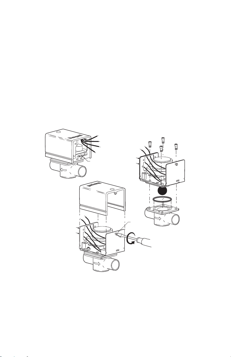
4. Remove the old powerhead from the valve body
(Fig. 4)
a. Place the manual opening lever (normally
closed models only) on the old powerhead in
the MAN. OPEN position (see Fig. 4A).
b. Remove the cover (Fig. 4B).
c. With the cover off, remove the four screws
securing the powerhead to the valve body.
d. Lift the powerhead off the valve body (Fig. 4C).
e. Remove the O-ring from the top of the valve
body.
Fig. 4. Remove old powerhead from systems using old style valve bodies
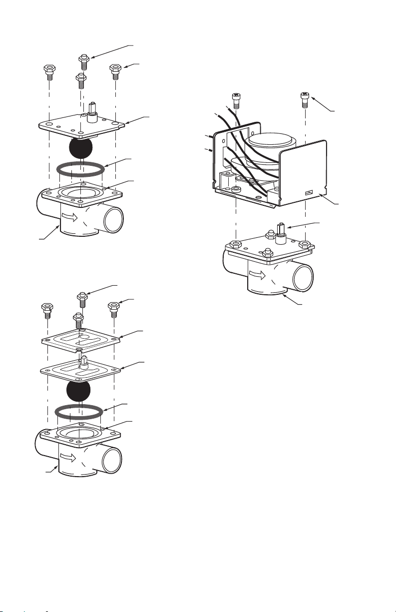
5. Install 40003918 Conversion Kit (Fig. 5)
a. Insert the new O-ring in the valve body.
b. Place metal plate with the rubber plug on top of
the valve body. Make sure the guide pins on the
underside of the metal plate fit into the recesses
on the valve body.
c. Secure the metal plate to the valve body with
the four screws (two sets) provided. One set of
screws has heads with recessed threads to
insert screws for mounting the new powerhead;
insert this set into the larger screw openings.
The other set has domed heads; insert this set
into the smaller screw openings. Each set of
screws must be inserted in opposite corners of
the metal plate so the screws sit flat on the
plate. Make sure the guide pins on the plate fit
into the recesses on the valve body.
A
AUTO
MAN
OPEN
MANUAL
OPENING
LEVER
COVER
RETAINING
SCREW
M10174
A
B
V8043F 1051
24V 50/60 CY
.32 AMP @ 60 CY
MADE IN CANADA
6
A
B
V8043F 1051
24V 50/60 CY
.32 AMP @ 60 CY
MADE IN CANADA
6
A
B
C
V4043, V4044 VALVES; V8043, V8044 ZONE VALVES
95-6983—11 4
Fig. 5a. Install 40003918 conversion kit with brass
adapter plate.
Fig. 5b. Install conversion kit with composite (steel &
plastic) adapter plate.
6. Install new powerhead (see Fig. 6)
a. Place the manual opening lever (normally
closed models only) on the new powerhead in
the MAN. OPEN position.
b. Fit the powerhead onto the valve body, ensuring
that the shaft seats correctly. The powerhead
should be aligned so that the manual opening
lever or slot for lever is at the port A end of the
valve body.
c. Secure the powerhead to the valve body with
the two screws provided.
d. If fitted, reconnect the conduit or cable. Recon-
nect the leadwires at the powerhead.
e. Replace the powerhead cover.
7. Turn on power.
Fig. 6. Install new powerhead.
SYSTEMS WITH NEW STYLE VALVE BODIES
(SERIES 6)
IMPORTANT
On a new style valve body that has been con-
verted to accept the new powerhead, it is not
necessary to drain the system if the valve body
remains in the pipeline.
1. Disconnect the power supply before connecting the
wiring to prevent electrical shock or equipment
damage.
2. Disconnect the leadwires to the powerhead at the
terminal block or conduit connection. Remove the
conduit or cable connector, if fitted. Label each wire
for rewiring later.
3. Remove the old powerhead (see Fig. 7):
a. Place the manual opening lever (normally
closed models only) on the old powerhead in
the MAN. OPEN position (Fig. 7A).
b. Remove the screw securing the cover to the
powerhead (Fig. 7B).
c. Lift off the cover from the powerhead.
d. Remove the two screws securing the power-
head to the valve body (Fig. 6).
e. Lift the powerhead off the valve body.
A
B
HEX-NUT SCREW
WITH DOMED HEADS (2)
HEX-NUT SCREWS
WITH RECESSED
THREADS AND
SHOULDER SHANK (2)
BRASS
ADAPTER
PLATE
O RING
LOCATING
RECESSES (3)
VALVE
BODY
M32317
STEEL
PLATE
A
B
HEX-NUT SCREW
WITH DOMED HEADS (2)
HEX-NUT SCREWS
WITH RECESSED
THREADS AND
SHOULDER SHANK (2)
PLASTIC
PLATE
O RING
LOCATING
RECESSES (3)
VALVE
BODY
M32316
A
B
V8043F 1036
24V 50/60 CY
.32 AMP @ 60 CY
MADE IN CANADA
6
SECURING
SCREW (2)
REMOVABLE
HEAD
SHAFT
REMOVABLE HEAD
VALVE BODY ASSEMBLY
M10173
Loading...