


UDC3500
Universal Digital Controller
Product Manual
51-52-25-120 Revision 4 March 2012
Honeywell Process Solutions

Notices and Trademarks
Copyright 2012 by Honeywell
Revision 4 March 2012
While this information is presented in good faith and believed to be accurate, Honeywell disclaims the implied warranties of merchantability and fitness for a particular purpose and makes no express warranties except as may be stated in its written agreement with and for its customers.
In no event is Honeywell liable to anyone for any indirect, special or consequential damages. The information and specifications in this document are subject to change without notice.
Honeywell, PlantScape, Experion PKS, and TotalPlant are registered trademarks of Honeywell International Inc.
Other brand or product names are trademarks of their respective owners.
Honeywell Process Solutions
1860 West Rose Garden Lane
Phoenix, Arizona 85027
.
ii |
UDC3500 Universal Digital Controller Product Manual |
March 2012 |

About This Document
Abstract
This document provides descriptions and procedures for the Installation, Configuration, Operation, and Troubleshooting of your UDC3500 Controller.
Revision Information
Document Name |
Document ID |
Revision |
Publication Date |
UDC3500 Universal Digital Controller |
|
Number |
|
|
|
|
|
Product Manual |
|
|
|
|
|
|
|
Input Voltage change |
51-52-25-120 |
4 |
March 2012 |
|
|
|
|
|
|
|
|
References
The following list identifies all documents that may be sources of reference for material discussed in this publication.
Document Title
Process Instrument Explorer manual |
51-52-25-131 |
How to Apply Digital Instrumentation in Severe Electrical Noise |
51-52-05-01 |
Environments. |
|
Modbus RTU Serial Communications User Manual |
51-52-25-66 |
MODBUS Messaging on TCP/IP Implementation Guide. |
51-52-25-121 |
March 2012 |
UDC3500 Universal Digital Controller Product Manual |
iii |

Support and Contact info
United States and Canada
Contact: |
Honeywell Process Solution |
|
Global Technical Support - Phone: 001-800-423-9883 |
|
Customer Service (HFS) - Phone: 001-800-343-0228 |
|
Outside United States - Phone: 001-215-641-3610 |
|
Calls are answered by dispatcher between 6:00 am and 4:00 pm Mountain Standard Time. |
|
Emergency calls outside normal working hours are received by an answering service and returned |
|
within one hour. |
Email support: |
ask-ssc@honeywell.com |
Mail: |
Honeywell Process Solutions |
|
1860 West Rose Garden Lane, |
|
Phoenix, Arizona 85027 |
For more contact details for Europe, Asia, North and South Americas, please see back page.
World Wide Web
Honeywell Process Solutions Support Online: www.honeywellprocess.com/
Elsewhere
Call your nearest Honeywell office.
Training Classes
Honeywell Automation College:
http://www.automationcollege.com
iv |
UDC3500 Universal Digital Controller Product Manual |
March 2012 |
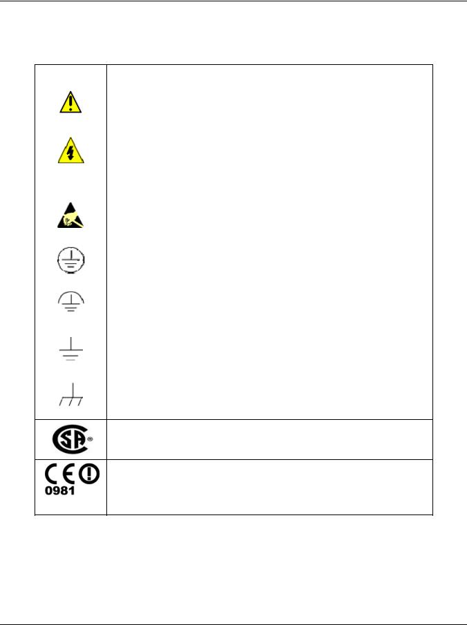
Symbol Definitions
The following table lists those symbols used in this document to denote certain conditions.
Symbol |
Definition |
This CAUTION symbol on the equipment refers the user to the Product Manual for additional information. This symbol appears next to required information in the manual.
WARNING
PERSONAL INJURY: Risk of electrical shock. This symbol warns the user of a potential shock hazard where HAZARDOUS LIVE voltages greater than 30 Vrms, 42.4 Vpeak, or 60 VDC may be accessible. Failure to comply with these instructions could result in death or serious injury.
ATTENTION, Electrostatic Discharge (ESD) hazards. Observe precautions for handling electrostatic sensitive devices
Protective Earth (PE) terminal. Provided for connection of the protective earth (green or green/yellow) supply system conductor.
Functional earth terminal. Used for non-safety purposes such as noise immunity improvement. NOTE: This connection shall be bonded to protective earth at the source of supply in accordance with national local electrical code requirements.
Earth Ground. Functional earth connection. NOTE: This connection shall be bonded to Protective earth at the source of supply in accordance with national and local electrical code requirements.
Chassis Ground. Identifies a connection to the chassis or frame of the equipment shall be bonded to Protective Earth at the source of supply in accordance with national and local electrical code requirements.
The Canadian Standards mark means the equipment has been tested and meets applicable standards for safety and/or performance.
For radio equipment used in the European Union in accordance with the R&TTE Directive the CE Mark and the notified body (NB) identification number is used when the NB is involved in the conformity assessment procedure. The alert sign must be used when a restriction on use (output power limit by a country at certain frequencies) applies to the equipment and must follow the CE marking.
March 2012 |
UDC3500 Universal Digital Controller Product Manual |
v |

|
|
Contents |
|
1 |
INTRODUCTION ................................................................................................... |
1 |
|
1.1 |
|
Overview......................................................................................................................................... |
1 |
1.2 |
|
Operator Interface ........................................................................................................................... |
6 |
|
1.2.1 Function of Displays and Keys ............................................................................................ |
7 |
|
1.3 |
|
Process Instrument Explorer Software............................................................................................ |
8 |
1.4 |
|
CE Conformity (Europe)............................................................................................................... |
10 |
2 |
INSTALLATION................................................................................................... |
11 |
|
2.1 |
|
Overview....................................................................................................................................... |
11 |
2.2 |
|
Condensed Specifications ............................................................................................................. |
13 |
2.3 |
|
Model Number Interpretation ....................................................................................................... |
17 |
2.4 |
|
Control and Alarm Relay Contact Information............................................................................. |
20 |
2.5 |
|
Mounting....................................................................................................................................... |
21 |
2.6 |
|
Wiring ........................................................................................................................................... |
23 |
|
2.6.1 Electrical Considerations ................................................................................................... |
23 |
|
2.7 |
|
Wiring Diagrams........................................................................................................................... |
25 |
3 |
CONFIGURATION............................................................................................... |
45 |
|
3.1 |
|
Overview....................................................................................................................................... |
45 |
3.2 |
|
Configuration Prompt Hierarchy .................................................................................................. |
47 |
3.3 |
|
Configuration Procedure............................................................................................................... |
51 |
3.4 |
|
Loop 1 Tuning Set Up Group ....................................................................................................... |
52 |
3.5 |
|
Loop 2 Tuning Set Up Group ....................................................................................................... |
56 |
3.6 |
|
SP Ramp Set Up Group ................................................................................................................ |
59 |
3.7 |
|
SP Program 2 Set Up Group ......................................................................................................... |
65 |
3.8 |
|
SP Program 3 Set Up Group ......................................................................................................... |
68 |
3.9 |
|
SP Program 4 Set Up Group ......................................................................................................... |
71 |
3.10 |
Accutune Set Up Group ............................................................................................................ |
74 |
|
3.11 |
Algorithm Set Up Group ........................................................................................................... |
79 |
|
3.12 |
Math Set Up Group ................................................................................................................... |
94 |
|
3.13 |
Logic Gates Set Up Group ...................................................................................................... |
100 |
|
3.14 |
Output Set Up Group............................................................................................................... |
107 |
|
3.15 |
Input 1 Set Up Group .............................................................................................................. |
118 |
|
3.16 |
Input 2 Set Up Group .............................................................................................................. |
122 |
|
3.17 |
Input 3 Set Up Group .............................................................................................................. |
125 |
|
3.18 |
Input 4 Set Up Group .............................................................................................................. |
128 |
|
|
|
|
|
vi |
|
UDC3500 Universal Digital Controller Product Manual |
March 2012 |

3.19 |
Input 5 Set Up Group .............................................................................................................. |
131 |
||
3.20 |
Control Set Up Group ............................................................................................................. |
134 |
||
3.21 |
Control 2 Set Up Group .......................................................................................................... |
143 |
||
3.22 |
Options Set Up Group ............................................................................................................. |
150 |
||
3.23 |
Communications Set Up Group............................................................................................... |
162 |
||
3.24 |
Alarms Set Up Group .............................................................................................................. |
166 |
||
3.25 |
Real Time Clock Set Up Group............................................................................................... |
174 |
||
3.26 |
Maintenance Set Up Group ..................................................................................................... |
175 |
||
3.27 |
Display Set Up Group ............................................................................................................. |
178 |
||
3.28 |
Read Maintenance Set Up Group............................................................................................ |
180 |
||
3.29 |
Time Events Set Up Group ..................................................................................................... |
181 |
||
3.30 |
P.I.E. Tool Ethernet and Email Configuration Screens........................................................... |
183 |
||
3.31 |
Configuration Record Sheet .................................................................................................... |
186 |
||
4 |
MONITORING AND OPERATING THE CONTROLLER................................... |
194 |
||
4.1 |
|
Overview..................................................................................................................................... |
194 |
|
4.2 |
|
Operator Interface ....................................................................................................................... |
195 |
|
4.3 |
Entering a Security Code ............................................................................................................ |
195 |
||
4.4 |
|
Lockout Feature .......................................................................................................................... |
196 |
|
4.5 |
|
Monitoring Your Controller........................................................................................................ |
198 |
|
|
4.5.1 |
Annunciators .................................................................................................................... |
198 |
|
|
4.5.2 Viewing the operating parameters.................................................................................... |
199 |
||
|
4.5.3 |
Diagnostic Messages ........................................................................................................ |
200 |
|
4.6 |
Start Up Procedure for Operation ............................................................................................... |
201 |
||
4.7 |
|
Control Modes ............................................................................................................................ |
202 |
|
|
4.7.1 |
Mode Definitions ............................................................................................................. |
202 |
|
|
4.7.2 What happens when you change modes........................................................................... |
203 |
||
4.8 |
|
Setpoints...................................................................................................................................... |
203 |
|
4.9 |
|
Timer |
........................................................................................................................................... |
205 |
4.10 |
Accutune .............................................................................................................................III |
206 |
||
|
4.10.1 ............................................................................................ |
Tune for Simplex Outputs |
208 |
|
|
4.10.2 ....................................................................................... |
Tune for Duplex (Heat/Cool) |
209 |
|
|
4.10.3 ................................. |
Using AUTOMATIC TUNE at start - up for Duplex (Heat/Cool) |
210 |
|
|
4.10.4 ...................................... |
Using BLENDED TUNE at start - up for Duplex (Heat/Cool) |
211 |
|
|
4.10.5 ....................................... |
Using MANUAL TUNE at start - up for Duplex (Heat/Cool) |
212 |
|
|
4.10.6 ............................................................................................ |
ACCUTUNE Error Codes |
213 |
|
4.11 |
Fuzzy .................................................................................................Overshoot Suppression |
214 |
||
4.12 |
Using ......................................................................................Two Sets of Tuning Constants |
215 |
||
4.13 |
Input ............................................................................................................Math Algorithms |
217 |
||
4.14 |
Logic ..............................................................................................................Gate Operation |
219 |
||
4.15 |
Digital ...............................................................................Input Option (Remote Switching) |
222 |
||
|
|
|
||
March 2012 |
UDC3500 Universal Digital Controller Product Manual |
vii |
||

4.16 |
Auto/Manual Station ............................................................................................................... |
227 |
||
4.17 |
Two Loops of Control ............................................................................................................. |
231 |
||
4.18 |
Configuring Two Loops of Control......................................................................................... |
234 |
||
4.19 |
Monitoring Two Loops of Control.......................................................................................... |
235 |
||
4.20 |
Operating Two Loops of Control ............................................................................................ |
236 |
||
4.21 |
Alarm Setpoints....................................................................................................................... |
237 |
||
4.22 |
Three Position Step Control Algorithm................................................................................... |
239 |
||
4.23 |
Setting a Failsafe Output Value for Restart After a Power Loss............................................. |
240 |
||
4.24 |
Setting Failsafe Mode.............................................................................................................. |
241 |
||
4.25 |
Carbon Potential, Oxygen and Dewpoint Algorithms............................................................. |
241 |
||
4.26 |
Healthwatch............................................................................................................................. |
244 |
||
4.27 |
Setpoint Rate/Ramp/Program Overview ................................................................................. |
244 |
||
4.28 |
Setpoint Rate ........................................................................................................................... |
245 |
||
4.29 |
Setpoint Ramp ......................................................................................................................... |
245 |
||
4.30 |
Setpoint Ramp/Soak Programming ......................................................................................... |
247 |
||
4.31 |
P.I.E. Tool Maintenance Screens ............................................................................................ |
262 |
||
4.32 |
Configuring your Ethernet Connection ................................................................................... |
272 |
||
5 |
INPUT CALIBRATION....................................................................................... |
279 |
||
5.1 |
|
Overview..................................................................................................................................... |
279 |
|
5.2 |
Minimum and Maximum Range Values ..................................................................................... |
280 |
||
5.3 |
|
Preliminary Information.............................................................................................................. |
282 |
|
5.4 |
Input Set Up Wiring.................................................................................................................... |
284 |
||
|
5.4.1 Thermocouple Inputs Using an Ice Bath.......................................................................... |
284 |
||
|
5.4.2 Thermocouple Inputs Using a Thermocouple Source...................................................... |
285 |
||
|
5.4.3 |
RTD Inputs....................................................................................................................... |
286 |
|
|
5.4.4 Radiamatic, Millivolts, Volts, Carbon, Oxygen or Thermocouple Differential Inputs.... |
287 |
||
|
5.4.5 0 to 10 Volts or –1 to 1 Volts........................................................................................... |
289 |
||
|
5.4.6 |
Milliamperes .................................................................................................................... |
290 |
|
|
5.4.7 Dual High Level Voltage Inputs ...................................................................................... |
291 |
||
|
5.4.8 Dual High Level Milliamperes Inputs.............................................................................. |
292 |
||
5.5 |
|
Input Calibration Procedure........................................................................................................ |
293 |
|
5.6 |
Restore Input Factory Calibration............................................................................................... |
295 |
||
6 |
OUTPUT CALIBRATION................................................................................... |
297 |
||
6.1 |
|
Overview..................................................................................................................................... |
297 |
|
6.2 |
First Current Output Calibration................................................................................................. |
298 |
||
6.3 |
Second Current Output Calibration............................................................................................. |
300 |
||
6.4 |
Third Current Output Calibration ............................................................................................... |
302 |
||
6.5 |
Position Proportional and Three Position Step Output Calibration ............................................ |
304 |
||
6.6 |
Restore Factory Output Calibration ............................................................................................ |
307 |
||
|
|
|
|
|
viii |
|
|
UDC3500 Universal Digital Controller Product Manual |
March 2012 |

7 |
TROUBLESHOOTING/SERVICE...................................................................... |
309 |
|
7.1 |
Overview..................................................................................................................................... |
309 |
|
7.2 |
Troubleshooting Aids.................................................................................................................. |
310 |
|
7.3 |
Power-up Tests............................................................................................................................ |
312 |
|
7.4 |
Status Tests ................................................................................................................................. |
312 |
|
7.5 |
Background Tests and Diagnostic Messages .............................................................................. |
313 |
|
7.6 |
Controller Failure Symptoms...................................................................................................... |
318 |
|
7.7 |
Troubleshooting Procedures ....................................................................................................... |
319 |
|
|
7.7.1 Procedure #1 – Power ...................................................................................................... |
320 |
|
|
7.7.2 Procedure #2 – Current Outputs....................................................................................... |
320 |
|
|
7.7.3 Procedure #3 – Position Proportional .............................................................................. |
322 |
|
|
7.7.4 Procedure #4 – Time Proportional ................................................................................... |
325 |
|
|
7.7.5 Procedure #5 – Current/Time or Time Current/Proportional........................................... |
326 |
|
|
7.7.6 Procedure #6 – Alarm Relays .......................................................................................... |
327 |
|
|
7.7.7 Procedure #7 – Keyboard................................................................................................. |
328 |
|
|
7.7.8 Procedure #8 – Analog Input ........................................................................................... |
329 |
|
|
7.7.9 Procedure #9 – RS-485 .................................................................................................... |
330 |
|
|
7.7.10 |
Procedure #10 – Ethernet ............................................................................................. |
332 |
|
7.7.11 |
Procedure #11 – Email ................................................................................................. |
333 |
7.8 |
Restoring Factory Configuration ................................................................................................ |
334 |
|
7.9 |
Software Upgrades...................................................................................................................... |
335 |
|
8 |
PARTS LIST ...................................................................................................... |
337 |
||
|
8.1 |
Exploded View............................................................................................................................ |
337 |
|
|
8.2 |
Removing the chassis.................................................................................................................. |
339 |
|
9 |
MODBUS RTU FUNCTION CODES.................................................................. |
340 |
||
|
9.1 |
Overview..................................................................................................................................... |
340 |
|
|
9.2 |
General Information.................................................................................................................... |
340 |
|
|
9.3 |
Function Code 20 (14h) - Read Configuration Reference Data.................................................. |
342 |
|
|
9.3.1 |
Read Configuration Examples ......................................................................................... |
344 |
|
|
9.4 |
Function Code 21 (15h) - Write Configuration Reference Data................................................. |
346 |
|
|
9.4.1 |
Write Configuration Examples ........................................................................................ |
348 |
|
10 MODBUS READ, WRITE AND OVERRIDE PARAMETERS PLUS EXCEPTION |
||||
CODES........................................................................................................................ |
|
349 |
||
|
10.1 |
Overview ................................................................................................................................. |
349 |
|
|
10.2 |
Reading Control Data.............................................................................................................. |
352 |
|
|
10.3 Read Software Options Status................................................................................................. |
353 |
||
|
10.4 |
Miscellaneous Read Onlys ...................................................................................................... |
354 |
|
10.4.1 |
Register Addresses for Read Onlys .............................................................................. |
354 |
10.4.2 |
SetPoint Program Read Only Information.................................................................... |
354 |
|
|
|
March 2012 |
UDC3500 Universal Digital Controller Product Manual |
ix |

10.5 |
Setpoints .................................................................................................................................. |
355 |
|
10.6 |
Using a Computer Setpoint (Overriding Controller Setpoint) ................................................ |
357 |
|
10.7 |
Configuration Parameters........................................................................................................ |
360 |
|
10.7.1 |
Tuning Loop 1 .............................................................................................................. |
360 |
|
10.7.2 |
Tuning Loop2 ............................................................................................................... |
362 |
|
10.7.3 |
SP Ramp/Rate/Program #1........................................................................................... |
363 |
|
10.7.4 |
Setpoint Program #2 ..................................................................................................... |
369 |
|
10.7.5 |
Setpoint Program #3 ..................................................................................................... |
375 |
|
10.7.6 |
Setpoint Program #4 ..................................................................................................... |
381 |
|
10.7.7 |
Accutune....................................................................................................................... |
387 |
|
10.7.8 |
Algorithm ..................................................................................................................... |
389 |
|
10.7.9 |
Math.............................................................................................................................. |
394 |
|
10.7.10 |
Logic............................................................................................................................. |
397 |
|
10.7.11 |
Output Algorithms........................................................................................................ |
401 |
|
10.7.12 |
Input 1........................................................................................................................... |
403 |
|
10.7.13 |
Input 2........................................................................................................................... |
405 |
|
10.7.14 |
Input 3........................................................................................................................... |
407 |
|
10.7.15 |
Input 4........................................................................................................................... |
409 |
|
10.7.16 |
Input 5........................................................................................................................... |
411 |
|
10.7.17 |
Control.......................................................................................................................... |
413 |
|
10.7.18 |
Control Loop 2 ............................................................................................................. |
416 |
|
10.7.19 |
Options ......................................................................................................................... |
419 |
|
10.7.20 |
Communications........................................................................................................... |
423 |
|
10.7.21 |
Alarms .......................................................................................................................... |
425 |
|
10.7.22 |
Maintenance ................................................................................................................. |
429 |
|
10.7.23 |
Time Event ................................................................................................................... |
432 |
|
10.7.24 |
Display.......................................................................................................................... |
434 |
|
10.7.25 |
Clock ............................................................................................................................ |
435 |
|
10.8 |
Modbus RTU Exception Codes............................................................................................... |
436 |
|
11 |
FURTHER INFORMATION................................................................................ |
|
438 |
|
|
11.1 |
Modbus RTU Serial Communications .................................................................................... |
|
438 |
|
11.2 |
Modbus Messaging on Ethernet TCP/IP ................................................................................. |
|
438 |
|
11.3 |
How to Apply Digital Instrumentation in Severe Electrical Noise Environments |
..................438 |
|
12 |
INDEX................................................................................................................ |
|
439 |
|
13 |
SALES AND SERVICE.............................. |
ERROR! BOOKMARK NOT DEFINED. |
||
x |
UDC3500 Universal Digital Controller Product Manual |
March 2012 |
Tables
Table 2-1 Condensed Specifications ____________________________________________________ 13 Table 2-2 Control Relay Contact Information _____________________________________________ 20 Table 2-3 Alarm Relay Contact Information ______________________________________________ 20 Table 2-4 Mounting Procedure _________________________________________________________ 22 Table 2-5 Permissible Wiring Bundling__________________________________________________ 24 Table 2-6 Single or Cascade Loop Controller – Loop 1 Output Functionality and Restrictions _______ 26 Table 2-7 Dual Loop Controller – Loop 2 Output Functionality and Restrictions __________________ 27 Table 2-8 Terminals for connecting a UDC to a MDI Compliant Hub or Switch utilizing a cross-over cable
______________________________________________________________________________ 41 Table 2-9 Terminals for connecting a UDC directly to a PC utilizing a straight-through cable ________ 42 Table 3-1 Configuration Topics ________________________________________________________ 45 Table 3-2 Configuration Prompt Hierarchy _______________________________________________ 47 Table 3-3 Configuration Procedure _____________________________________________________ 51 Table 3-4 TUNING Group Function Prompts _____________________________________________ 52 Table 3-5 TUNING 2 Group Function Prompts____________________________________________ 56 Table 3-6 SPRAMP Group Function Prompts _____________________________________________ 60 Table 3-7 SP PROG2 Group Function Prompts____________________________________________ 65 Table 3-8 SP PROG3 Group Function Prompts____________________________________________ 68 Table 3-9 SP PROG4 Group Function Prompts____________________________________________ 71 Table 3-10 ACCUTUNE Group Function Prompts _________________________________________ 75 Table 3-11 ALGORTHM Group Function Prompts ________________________________________ 79 Table 3-12 MATH Group Function Prompts ______________________________________________ 94 Table 3-13 LOGIC Group Function Prompts _____________________________________________ 100 Table 3-14 OUTPUT Group Function Prompts ___________________________________________ 107 Table 3-15 INPUT 1 Group Function Prompts ___________________________________________ 118 Table 3-16 INPUT 2 Group Function Prompts ___________________________________________ 122 Table 3-17 INPUT 3 Group Function Prompts ___________________________________________ 125 Table 3-18 INPUT 4 Group Function Prompts ___________________________________________ 128 Table 3-19 INPUT 5 Group Function Prompts ___________________________________________ 131 Table 3-20 CONTROL Group Function Prompts __________________________________________ 134 Table 3-21 CONTROL2 Group Function Prompts _________________________________________ 143 Table 3-22 OPTION Group Function Prompts ___________________________________________ 150 Table 3-23 Communications Group Function Prompts _____________________________________ 162 Table 3-24 ALARMS Group Function Prompts __________________________________________ 167 Table 3-25 CLOCK Group Function Prompts ____________________________________________ 174 Table 3-26 MAINTENANCE Group Function Prompts ____________________________________ 175 Table 3-27 DISPLAY Group Function Prompts __________________________________________ 178 Table 3-28 READ MAINTENANCE Group Function Prompts ______________________________ 180 Table 3-29 TIME EVT Group Function Prompts _________________________________________ 181 Table 3-30 Configuration Record Sheet _________________________________________________ 186 Table 4-1 Procedure to Enter a Security Code ____________________________________________ 196 Table 4-2 Annunciators _____________________________________________________________ 198 Table 4-3 Lower Display Key Parameter Prompts_________________________________________ 199 Table 4-4 Procedure for Starting Up the Controller ________________________________________ 201 Table 4-5 Control Mode Definitions ___________________________________________________ 202 Table 4-6 Changing Control Modes ____________________________________________________ 203 Table 4-7 Procedure for Changing the Local Setpoints _____________________________________ 204 Table 4-8 Procedure for Switching Between Setpoints _____________________________________ 204
March 2012 |
UDC3500 Universal Digital Controller Product Manual |
xi |

Table 4-9 Procedure for Starting “TUNE”_______________________________________________ 208 Table 4-10 Procedure for Using AUTOMATIC TUNE at Start-up for Duplex Control ____________ 210 Table 4-11 Procedure for Using BLENDED TUNE at Start-up for Duplex Control_______________ 211 Table 4-12 Procedure for Using MANUAL TUNE for Heat side of Duplex Control ______________ 212 Table 4-13 Procedure for Using MANUAL TUNE for Cool side of Duplex Control ______________ 212 Table 4-14 Procedure for Accessing Accutune Error Codes _________________________________ 213 Table 4-15 Accutune Error Codes _____________________________________________________ 213 Table 4-16 Set Up Procedure _________________________________________________________ 215 Table 4-17 Procedure for Switching PID SETS from the Keyboard ___________________________ 216 Table 4-18 Logic Gates Constraints and Dynamic Operation Status ___________________________ 220 Table 4-19 Digital Input Option Action on Contact Closure _________________________________ 222 Table 4-20 Digital Input Combinations “DIG IN1” or “DIG IN2” ____________________________ 225 Table 4-21 Digital Inputs 1 and 2 Combination___________________________________________ 226 Table 4-22 Auto/Manual Station Mode Configuration Procedure _____________________________ 228 Table 4-23 Procedure for selecting Two Loop Algorithm ___________________________________ 234 Table 4-24 Digital Display Indication—Two Loops _______________________________________ 235 Table 4-25 Procedure for Displaying Alarm Setpoints _____________________________________ 237 Table 4-26 Procedure for Displaying TPSC Motor Position _________________________________ 239 Table 4-27 Procedure for Setting a Failsafe Value_________________________________________ 240 Table 4-28 Procedure for Setting a Failsafe Mode_________________________________________ 241 Table 4-29 Running A Setpoint Ramp __________________________________________________ 246 Table 4-30 Program Contents_________________________________________________________ 248 Table 4-31 Ramp/Soak Profile Example (Using 12 Segments) _______________________________ 251 Table 4-32 Program #1 Record Sheets __________________________________________________ 252 Table 4-33 Program #2 Record Sheets __________________________________________________ 254 Table 4-34 Program #3 Record Sheets __________________________________________________ 256 Table 4-35 Program #4 Record Sheets __________________________________________________ 258 Table 4-36 Run/Monitor Functions ____________________________________________________ 260 Table 5-1 Voltage, Milliamp and Resistance Equivalents for Input Range Values _______________ 280 Table 5-2 Equipment Needed_________________________________________________________ 282 Table 5-3 Set Up Wiring Procedure for Thermocouple Inputs Using an Ice Bath ________________ 284 Table 5-4 Set Up Wiring Procedure for Thermocouple Inputs using a Thermocouple Source _______ 285 Table 5-5 Set Up Wiring Procedure for RTD Inputs _______________________________________ 286 Table 5-6 Set Up Wiring Procedure for Radiamatic, Millivolts, Volts, Carbon, Oxygen or Thermocouple
Differential Inputs (Except 0-10 Volts and –1 to 1 Volts) ________________________________ 287 Table 5-7 Procedure to determine calibration voltages for Thermocouple Differential input types other than the
Factory Setting _________________________________________________________________ 288 Table 5-8 Set Up Wiring Procedure for 0 to 10 Volts or –1 to 1 Volts _________________________ 289 Table 5-9 Set Up Wiring Procedure for Milliampere Inputs _________________________________ 290 Table 5-10 Set Up Wiring Procedure for Dual High Level Voltage Inputs ______________________ 291 Table 5-11 Set Up Wiring Procedure for Dual High Level Milliampere Inputs __________________ 292 Table 5-12 Input Calibration Procedure _________________________________________________ 293 Table 5-13 Restore Factory Calibration _________________________________________________ 295 Table 6-1 Set Up Wiring Procedure for the First Current Output _____________________________ 298 Table 6-2 First Current Output Calibration Procedure______________________________________ 299 Table 6-3 Set Up Wiring Procedure for the Second Current Output ___________________________ 300 Table 6-4 Second Current Output Calibration Procedure ___________________________________ 301 Table 6-5 Set Up Wiring Procedure for the Third Current Output ____________________________ 302 Table 6-6 Third Current Output Calibration Procedure _____________________________________ 303 Table 6-7 Position Proportional and Three Position Step Output Calibration Procedure ___________ 305
xii |
UDC3500 Universal Digital Controller Product Manual |
March 2012 |

Table 6-8 Restore Factory Calibration __________________________________________________ 307 Table 7-1 Procedure for Identifying the Software Version __________________________________ 311 Table 7-2 Procedure for Displaying the Status Test Results _________________________________ 312 Table 7-3 Background Tests__________________________________________________________ 313 Table 7-4 Controller Failure Symptoms_________________________________________________ 318 Table 7-5 Troubleshooting Power Failure Symptoms ______________________________________ 320 Table 7-6 Troubleshooting Current Output Failure ________________________________________ 320 Table 7-7 Troubleshooting Position Proportional Output Failure _____________________________ 322 Table 7-8 Troubleshooting Time Proportional Output Failure _______________________________ 325 Table 7-9 Troubleshooting Current/Time or Time/Current Proportional Output Failure ___________ 326 Table 7-10 Troubleshooting Alarm Relay Output Failure ___________________________________ 327 Table 7-11 Troubleshooting a Keyboard Failure __________________________________________ 328 Table 7-12 Troubleshooting an Analog Input Failure ______________________________________ 329 Table 7-13 Troubleshooting a RS-485 Communications Failure______________________________ 330 Table 7-14 Troubleshooting an Ethernet Communications Failure ____________________________ 332 Table 7-15 Troubleshooting an Email Failure ____________________________________________ 333 Table 7-16 Restoring Factory Configuration _____________________________________________ 334 Table 7-17 Software Upgrades________________________________________________________ 335 Table 8-1 Parts Identification _________________________________________________________ 338 Table 8-2 Parts Not Shown___________________________________________________________ 338 Table 8-3 Software Upgrades (see Section 7.9) ___________________________________________ 339 Table 9-1 Integer Parameter Type _____________________________________________________ 341 Table 9-2 Floating Point Parameter Type________________________________________________ 341 Table 9-3 Register Parameter ID Address Format for Function Code 20 _______________________ 343 Table 9-4 Register Parameter ID Address Format for Function Code 21 _______________________ 347 Table 10-1 Control Data Parameters ___________________________________________________ 352 Table 10-2 Option Status ____________________________________________________________ 353 Table 10-3 Miscellaneous Read Onlys__________________________________________________ 354 Table 10-4 SetPoint Program Read Only Information ______________________________________ 354 Table 10-5 Setpoint Code Selections ___________________________________________________ 355 Table 10-6 Setpoint Associated Parameters ______________________________________________ 356 Table 10-7 Computer Setpoint Selection ________________________________________________ 357 Table 10-8 Computer Setpoint Associated Parameters for Loop 1 ____________________________ 358 Table 10-9 Computer Setpoint Associated Parameters for Loop2 _____________________________ 359 Table 10-10 Set-up Group – Tuning Loop 1 _____________________________________________ 360 Table 10-11 Set-up Group – Tuning Loop 2______________________________________________ 362 Table 10-12 Set-up Group – Setpoint Ramp/Rate/Program #1 _______________________________ 363 Table 10-13 Set-up Group – Setpoint Program #2_________________________________________ 369 Table 10-14 Set-up Group – Setpoint Program #3_________________________________________ 375 Table 10-15 Set-up Group – Setpoint Program #4_________________________________________ 381 Table 10-16 Set-up Group – Adaptive Tune _____________________________________________ 387 Table 10-17 Set-up Group – Algorithm _________________________________________________ 389 Table 10-18 Set-up Group – Math _____________________________________________________ 394 Table 10-19 Set-up Group – Logic_____________________________________________________ 397 Table 10-20 Set-up Group – Output Algorithms __________________________________________ 401 Table 10-21 Set-up Group – Input 1____________________________________________________ 403 Table 10-22 Set-up Group – Input 2____________________________________________________ 405 Table 10-23 Set-up Group – Input 3____________________________________________________ 407 Table 10-24 Set-up Group – Input 4____________________________________________________ 409 Table 10-25 Set-up Group – Input 5____________________________________________________ 411
March 2012 |
UDC3500 Universal Digital Controller Product Manual |
xiii |

Table 10-26 Set-up Group – Control ___________________________________________________ 413 Table 10-27 Set-up Group – Control2 __________________________________________________ 416 Table 10-28 Set-up Group – Options ___________________________________________________ 419 Table 10-29 Set-up Group – Communications____________________________________________ 423 Table 10-30 Set-up Group – Alarms ___________________________________________________ 425 Table 10-31 Set-up Group – Maintenance _______________________________________________ 429 Table 10-32 Set-up Group – Time Event ________________________________________________ 432 Table 10-33 Set-up Group – Display ___________________________________________________ 434 Table 10-34 Set-up Group – Clock ____________________________________________________ 435 Table 10-35 Modbus RTU Data Layer Status Exception Codes ______________________________ 437
xiv |
UDC3500 Universal Digital Controller Product Manual |
March 2012 |

Figures
Figure 1-1 UDC3500 Operator Interface __________________________________________________ 6 Figure 1-2 Screen capture of Process Instrument Explorer running on a Pocket PC _________________ 8 Figure 1-3 Depiction of infrared communications ___________________________________________ 9 Figure 2-1 Model Number Interpretation _________________________________________________ 17 Figure 2-2 Mounting Dimensions (not to scale)____________________________________________ 21 Figure 2-3 Mounting Methods _________________________________________________________ 22 Figure 2-4 Composite Wiring Diagram___________________________________________________ 28 Figure 2-5 Mains Power Supply ________________________________________________________ 29 Figure 2-6 Input 1 Connections_________________________________________________________ 30 Figure 2-7 Input 2 Connections_________________________________________________________ 31 Figure 2-8 Input 3 Connections_________________________________________________________ 32 Figure 2-9 HLAI Inputs 2 and 4 Connections ______________________________________________ 33 Figure 2-10 HLAI Inputs 3 and 5 Connections _____________________________________________ 34 Figure 2-11 Optional Analog Input Jumper Positions________________________________________ 34 Figure 2-12 First Current Output________________________________________________________ 35 Figure 2-13 Second Current Output _____________________________________________________ 35 Figure 2-14 Output #2 – Electromechanical Relay Output ____________________________________ 36 Figure 2-15 Output #2 – Solid State Relay Output __________________________________________ 36 Figure 2-16 Output #2 – Open Collector OutputThird ______________________________________ 37 Figure 2-17 Output #2 – Third Current Output_____________________________________________ 37 Figure 2-18 Output #2 – Dual Relay Output for Time Duplex _________________________________ 38 Figure 2-19 Output #2 – Dual Relay Output for Position Proportional or Three Position Step Control _ 38 Figure 2-20 RS-422/485 Communications Option Connections________________________________ 39 Figure 2-21 Ethernet Communications Option with Adaptor Board_____________________________ 39 Figure 2-22 Ethernet Communications Option without Adaptor Board __________________________ 40 Figure 2-23 Digital Inputs _____________________________________________________________ 42 Figure 2-24 Optional Electromechanical Relay Outputs______________________________________ 43 Figure 2-25 Transmitter Power for 4-20 mA — 2 wire Transmitter Using Open Collector Output_____ 43 Figure 2-26 Transmitter Power for 4-20 mA — 2 Wire Transmitter Using Second Current Output ____ 44 Figure 3-1 Mass Flow Example ________________________________________________________ 92 Figure 3-2 Example of Eight Segment Characterizer________________________________________ 99 Figure 3-3 Ethernet Configuration Screen _______________________________________________ 183 Figure 3-4 Email Configuration Screen _________________________________________________ 184 Figure 4-1 Operator Interface_________________________________________________________ 195 Figure 4-2 Auto/Manual Station for Loop 1 (Loop 2 similar) ________________________________ 227 Figure 4-3 Functional Overview Block Diagram of a Single Loop (Loop #1) or
Dual Loop Controller (Loop #1 and Loop #2)_________________________________________ 232 Figure 4-4 Functional Overview Block Diagram of Internal Cascade Controller _________________ 233 Figure 4-5 Hi/Lo Override Selector ____________________________________________________ 234 Figure 4-6 Carbon Potential Control ___________________________________________________ 243 Figure 4-7 Ramp/Soak Profile Example_________________________________________________ 251 Figure 4-8 SP Program #1 Record Sheets _______________________________________________ 252 Figure 4-9 SP Program #2 Record Sheets _______________________________________________ 254 Figure 4-10 SP Program #3 Record Sheets ______________________________________________ 256 Figure 4-11 SP Program #4 Record Sheets ______________________________________________ 258 Figure 4-12 Loop Data Maintenance Screen _____________________________________________ 262 Figure 4-13 Alarm Details Maintenance Screen __________________________________________ 263 Figure 4-14 Digital Inputs Details Maintenance Screen_____________________________________ 264
March 2012 |
UDC3500 Universal Digital Controller Product Manual |
xv |

Figure 4-15 Status Data Maintenance Screen_____________________________________________ 265 Figure 4-16 Diagnostic History Maintenance Screen_______________________________________ 266 Figure 4-17 Ethernet Status Maintenance Screen__________________________________________ 267 Figure 4-18 Healthwatch Data Maintenance Screen _______________________________________ 268 Figure 4-19 Healthwatch Data Reset Screen _____________________________________________ 269 Figure 4-20 Totalizer Maintenance Screen ______________________________________________ 270 Figure 4-21 Real Time Clock Maintenance Screen ________________________________________ 271 Figure 4-22 IR Communications Address _______________________________________________ 272 Figure 4-23 Configuration Upload in Progress ___________________________________________ 273 Figure 4-24 Ethernet Communications Address __________________________________________ 275 Figure 4-25 Configuration Upload in Progress ___________________________________________ 276 Figure 5-1 Input Wiring Terminals ____________________________________________________ 282 Figure 5-2 Wiring Connections for Thermocouple Inputs Using an Ice Bath ____________________ 284 Figure 5-3 Wiring Connections for Thermocouple Inputs Using a Thermocouple Source __________ 285 Figure 5-4 Wiring Connections for RTD (Resistance Thermometer Device) ____________________ 286 Figure 5-5 Wiring Connections for Radiamatic, Millivolts, Volts, Carbon, Oxygen or
Thermocouple Differential Inputs (Except 0-10 Volts and –1 to 1 Volts)____________________ 287 Figure 5-6 Wiring Connections for 0 to 10 Volts or –1 to 1 Volts_____________________________ 289 Figure 5-7 Wiring Connections for Milliampere Inputs_____________________________________ 290 Figure 5-8 Wiring Connections for Dual High Level Voltage Inputs __________________________ 291 Figure 5-9 Wiring Connections for Dual High Level Milliampere Inputs_______________________ 292 Figure 6-1 Wiring Connections for Calibrating the First Current Output _______________________ 298 Figure 6-2 Wiring Connections for Calibrating the Second Current Output _____________________ 300 Figure 6-3 Wiring Connections for Calibrating Third Current Output _________________________ 302 Figure 8-1 UDC3500 Exploded View __________________________________________________ 337 Figure 10-1 Software Option Status Information __________________________________________ 353
xvi |
UDC3500 Universal Digital Controller Product Manual |
March 2012 |

Introduction
1 Introduction
1.1 Overview
Function
The UDC3500 is a microprocessor-based stand-alone controller. It combines a high degree of functionality and operating simplicity in a 1/4 DIN size controller. This instrument is an ideal controller for regulating temperature and other process variables in numerous heating and cooling applications, as well as in metal working, food, pharmaceuticals, semiconductor, testing and environmental work.
The UDC3500 monitors and controls temperatures and other variables in applications such as environmental chambers, plastic processing machines, furnaces and ovens, and packaging machinery.
Features
3 Universal Analog Inputs (can be configured to act as one Universal and four High Level)
± 0.10% Analog Input Accuracy (can be Field Calibrated to ± 0.05%)
16-bit Analog Input resolution typical
Fast scanning rate (166ms)
Up to 7 Analog and Digital Outputs
4 Digital Inputs
Two Math Functions, two Characterizers, one Polynomial equation and one Totalizer available
Two Independent Loops or Cascade Loop
Up to four 20-segment Setpoint Programs (can be concatenated to form two 40segment Setpoint Programs)
Ethernet TCP/IP with Email or RS-485 Modbus communication
Infrared PC & Pocket PC configuration
NEMA4X and IP66 front face protection
Multilanguage prompts
¼ DIN Size
Easily Field Upgradeable
Easy to read displays
Bright, dual displays with multi-language prompts (in English, French, German, Spanish, or Italian) make the operator interface easy to read, understand, and operate. Simple keystrokes let you set operating parameters that meet your process control needs.
March 2012 |
UDC3500 Universal Digital Controller Product Manual |
1 |

Introduction
Analog Inputs
The UDC3500 has three universal analog inputs with a typical accuracy of ±0.10% of full-scale input and a typical resolution of 16 bits. These can be configured to act as one Universal and four High Level Inputs for a total of five analog inputs. All analog inputs are sampled six times per second (every 166 ms).
The Process Variable input can be one of the various Thermocouple, RTD, Radiamatic or linear actuations. Linear actuations have Thermocouple, RTD, and Radiamatic transmitter characterization capability as a standard feature. Linear actuations also have square root capability.
The optional second and third inputs are isolated from each other and all other inputs and outputs and accept the same actuations as input one. Input 3 provides the Slidewire input for Position Proportional control. These optional inputs can each be split into two high level inputs. The fourth input is enabled by first configuring Input 2 as a 20 mA or 5 Vdc input type (high level) and moving a jumper on the Second Optional Input Board. Input 4 will then be available as a high level input. The fifth input is enabled by first configuring Input 3 as a 20 mA or 5 Vdc input type (high level) and moving a jumper on the Third Optional Input Board. Input 5 will then be available as a high level input.
All actuations and characterizations are keyboard configurable. Cold junction compensation is provided for thermocouple type inputs. Upscale, downscale or failsafe sensor break protection is keyboard configurable. A configurable digital filter of 0 to 120 seconds provides input signal damping.
Thermocouple Health—In addition to the standard configurable upscale, downscale or failsafe output burnout selections, the condition of the thermocouple can be monitored to determine if it is good, failing or in danger of imminent failure.
Math Functions
Algorithm—Two pre-configured algorithms are available for easy implementation. This includes the capability of using a Ratio and Bias with any input. You can select from the following menu:
Feedforward Summer—Uses any input, followed by a Ratio/Bias calculation, summed directly with the computed PID output value to provide a resultant output to the final control element (standard feature).
Weighted Average —Computes the weighted average of a PV or SP for the control algorithm from two inputs (standard feature).
Feedforward Multiplier—Uses any input, multiplied by the calculated PID output to provide a resultant output, which is sent to the final control element (standard feature).
Summer/Subtractor—Will add or subtract inputs with the result used as the derived PV.
Multiplier/Divider—Uses the analog inputs to calculate a derived PV. It is available with or without Square Root.
Input High/Low Select—Specifies the PV input as the higher or lower of two inputs.
2 |
UDC3500 Universal Digital Controller Product Manual |
March 2012 |

Introduction
8 Segment Characterizers—Two characterizers are available that can be applied to any Analog Input, to Loop 1 Output or to Loop 2 Output. The Characterizers can be combined to produce a single 16-segment characterizer. †
Totalizer—Calculates and displays the total flow volume as measured by any of the analog inputs or as derived by either Math algorithm. Displayed value is eight digits with a configurable scaling factor. The totalizer value may be reset.
Combinational Inputs—Inputs can be combined for use with Relative Humidity, % Oxygen, Carbon Potential, Dewpoint or Math Algorithms. This controller can accept carbon probes from Cambridge, Marathon Monitors, Corning, A.A.A.C, Barber Coleman, MacDhui, Bricesco or Furnace Controls.
Polynomial Curve Characterizer—A fifth order polynomial equation can be used on any one of the analog inputs.
Logic Gates—Five Logic Gates configurable as OR, NOR, AND, NAND, XOR, XNOR, or COMPARATOR. Each Gate has two inputs and one output. The Gates may be linked together to perform more complex functions.
† Characterizers are mutually exclusive with Setpoint Program #4.
Digital Inputs
Four isolated digital inputs are provided for remote dry contact closure to select one of 25 actions. Also, two of these digital inputs can allow one of six additional selections to be combined with one of the above selections.
Outputs
Output Types - The UDC3500 may have up to seven of the following outputs:
Current Outputs (4-20 or 0-20 mA)
Electromechanical Relays (5 amps)
Solid State Relay (1 amp)
Dual Electromechanical Relays (2 amps)
Open Collector Output (+30 VDC @ 20 mA)
Alarms
Up to four electromechanical alarm relays are available to activate external equipment when preset alarm setpoints are reached. Each of the four alarms can be set to monitor two independent setpoints. Each alarm setpoint can be either high or low alarm. The alarm type can be selected to be either of the inputs, the Process Variable, Deviation, Output, Shed from communications, PV rate of change, or to alarm on manual mode activation or a Current Output Open failure. It can also be used as an On or Off event at the beginning or end of a Ramp/Soak segment. An individual alarm hysteresis setting is provided for each relay and these are configurable from 0 to 100% of range.
Alarms can be configured as latching or non-latching. continued
March 2012 |
UDC3500 Universal Digital Controller Product Manual |
3 |

Introduction
Alarm blocking is also available which allows start-up without alarm energized until after it first reaches the operating region.
PV rate of change alarm.
Loop break alarm.
Timer output reset.
Diagnostic Alarm
Communications
A communications link is provided between the UDC3500 and a host computer or PLC via the RS422/485 Modbus® RTU or Ethernet TCP/IP * communications option. An infrared communication link is also available allowing a non-intrusive configuration of the instrument.
Miscellaneous Features
Auxiliary Output * (optional)—All of the three current outputs can function as Auxiliary Outputs which can be scaled from 4-20 ma for 0 to 100% for any range. These can be configured to represent any analog input, PV, active Setpoint, Local SP1, Deviation, or the Control Output for either control loop.
Transmitter Power—This feature provides up to 30 volts dc to power a 2-wire transmitter (requires the use of open collector output selection or one of the current outputs).
Four Local and one Remote Setpoints—Can be configured to provide four Local and one Remote Setpoints, which are selectable either via the keyboard or by Digital Input.
Universal Switching Power—Operates on any line voltage from 90 to 250 Vac 50/60 Hz without jumpers. 24 Vac/dc instrument power is available as an option.
Timer—This standard feature provides a configurable time period of 0 to 99 hours, 59 minutes or units of minutes and seconds. It can be started via the keyboard, alarm 2, or by a digital input. The timer output is Alarm 1, which energizes at the end of the Timer Period. Alarm 1 can be automatically reset. The Timer Period can be changed between each batch. Status is shown on the lower display.
Healthwatch—Consists of three timers and three counters, which can each be assigned to track UDC3500 controller functions. Selected Maintenance & Diagnostic data can be accessed from the front panel or via communications. Alarms can be configured to activate when a desired threshold is reached. A security code is required to perform resetting of any of the above listed counter or timer functions.
Real Time Clock—An optional battery-backed clock feature that allows the user to perform such things as starting an SP Program on a specific date and time.
Auto/Manual Station Plus Back-up Control—A UDC3500 can act as both an Auto/Manual Station PLUS as a back-up PID Controller, should the primary loop controller fail. Since the PID control is sometimes implemented via a PLC, this feature provides a very cost-effective way to insure the process does not have to shutdown or
4 |
UDC3500 Universal Digital Controller Product Manual |
March 2012 |
Introduction
remain in manual mode if the PLC should fail. Switching from the Auto/Manual Station to the back-up control mode is accomplished using the Digital Input option.
Moisture Protection—The NEMA4X and IP66 rated front face permits use in applications where it may be subjected to moisture, dust, or hose-down conditions. UL and CSA approved as Type 4 protection.
Setpoint Ramp/Soak Programming (Optional)—Enables you to program and store ten Ramp and ten Soak segments (total of twenty segments) for setpoint programming. Run or Hold of program is keyboard or remote digital switch selectable.
Enhanced Setpoint Programming (Optional) )—Four Setpoint Programs each of ten Ramp and ten Soak Segments. Each pair can be concatenated so as to form a single Setpoint Program of twenty Ramps and twenty Soaks. †
Setpoint Rate—Lets you define a ramp rate to be applied to any local setpoint change. A separate upscale or downscale rate is configurable. A single setpoint ramp is also available as an alternative.
Output Rate Limiter—A maximum output rate may be configured for both the upscale and the downscale output directions.
CE Mark—Conformity with 73/23/EEC, Low Voltage Directive and 89/336/EEC, the EMC Directive as a standard feature.
Approval Body Options—CSA certification and UL listing are available as an option.
Four Sets of Tuning Constants—Four sets of PID parameters can be configured for each loop and automatically or keyboard selected.
Data Security—Five levels of keyboard security protect tuning, configuration, and calibration data, accessed by a configurable 4-digit code. Nonvolatile EEPROM memory assures data integrity during loss of power.
Diagnostic/Failsafe Outputs—Continuous diagnostic routines detect failure modes, trigger a failsafe output value and identify the failure to minimize troubleshooting time.
High Noise Immunity—The controller is designed to provide reliable, error-free performance in industrial environments that often affect highly noise-sensitive digital equipment.
Accutune III™ —This standard feature provides a truly plug and play tuning algorithm, which will, at the touch of a button or through a digital input, accurately identify and tune any process including those with deadtime and integrating processes. This speeds up and simplifies start-up plus allows retuning at any setpoint. The algorithm used is an improved version of the Accutune IITM algorithm found on earlier controllers. Two possibilities are now offered when tuning your process: Fast Tune and Slow Tune.
Fast Tune will tune the process in such a way that the temp is reached faster, a slight overshoot will be allowed.
Slowtune will minimize overshoot, but it will take more time for the process temperature to reach the target setpoint.
March 2012 |
UDC3500 Universal Digital Controller Product Manual |
5 |

Introduction
Heat/Cool (Duplex Tune) will automatically tune both the heating and cooling sides of the process.
Fuzzy Logic—This standard feature uses fuzzy logic to suppress process variable overshoot due to SP changes or externally induced process disturbances. It operates independently from Accutune III tuning. It does not change the PID constants, but temporarily modifies the internal controller response to suppress overshoot. This allows more aggressive tuning to co-exist with smooth PV response. It can be enabled or disabled depending on the application or the control criteria.
*The Second Current Output option is mutually exclusive with the Ethernet Communications option.
†Characterizers are mutually exclusive with Setpoint Program #4.
1.2Operator Interface
Figure 1-1 UDC3500 Operator Interface
6 |
UDC3500 Universal Digital Controller Product Manual |
March 2012 |

Introduction
1.2.1 Function of Displays and Keys
Table 1-1 Function of Displays and Keys
Display Indicators
35002 |
Upper display with 4 larger digits shows |
|
Process Variable value (normal operation) |
||
|
||
|
and special annunciator features. During |
|
|
Configuration, the upper display provides |
|
|
guidance for the operator through prompts (7 |
|
|
– characters) |
|
|
|
|
During normal operation, the lower display |
SP 3500 |
||||
|
|
|
|
shows key-selected operating parameters |
|
|
|
|
|
|
|
|
|
such as Output, Setpoints, Inputs, Deviation, |
|
|
|
|
active Tuning Parameter Set, Timer Status, or |
|
|
|
|
minutes remaining in a setpoint ramp (4 |
|
|
|
|
digits). During configuration, the lower display |
|
|
|
|
provides guidance for the operator through |
|
|
|
|
prompts (8-characters). |
|
|
|
|
Indicates Alarm 1 and/or Alarm 2 conditions |
|
ALM |
|
||
|
|
|
|
exist. |
|
|
|
|
|
|
|
|
Indicates Digital Input 1 and/or 2 on. |
|
|
|
DI |
|
|
OUT
F
Or
C
MAN
Or
A
SP
Indicates Control Relay 1 and/or 2 on.
Indicates either degrees Fahrenheit or Centigrade.
Indicates either Manual or Auto mode.
Indicates Local Setpoint #1. Also, a bar is lighted when the setpoint being used is shown on the lower display.
Keys and Functions
Func
Loop 1/2
Setup
Lower
Display
Selects functions within each configuration group. Switches between Loop Displays for Two Loop and Cascade units.
Scrolls through the configuration groups.
Returns Controller to normal display from Set Up mode. Toggles various operating parameters for display.
Increases setpoint or output value. Increases the configuration values or changes functions in Configuration mode groups.
Infrared transceiver
Man
Auto
SP
Select
Run
Hold
Selects Manual or Auto mode.
Hold key down to cycle through configured setpoints.
Enables Run/Hold of the SP Ramp or Program plus Timer start.
Decreases setpoint or output value. Decreases the configuration values or changes functions in Configuration mode groups.
NEMA4X and IP66 screw attachment (each corner)
March 2012 |
UDC3500 Universal Digital Controller Product Manual |
7 |
Introduction
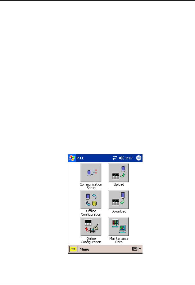
1.3 Process Instrument Explorer Software
Overview
Process Instrument Explorer (P.I.E.) lets you configure your instrument on a desktop/laptop or Pocket PC. For details see Process Instrument Explorer Manual #51- 52-25-131.
Features
Create configurations with intuitive software program running on a Pocket PC, a Desktop or a laptop computer.
Create/edit configurations live, just connect software to the controller via a communications port.
Create/edit configurations offline and download to controller later via a communications port.
Communication types available on every UDC3500:
Infrared (standard)
RS 485 (optional)
Ethernet (optional)
Same port types on UDC2500 and UDC3200 allow interconnectivity.
This software is available in English, Spanish, Italian, German and French.
Figure 1-2 Screen capture of Process Instrument Explorer running on a Pocket PC
8 |
UDC3500 Universal Digital Controller Product Manual |
March 2012 |

Introduction
Infrared communications
The infrared connection provides a non-intrusive wireless connection with the instrument and maintains NEMA4X AND IP66 integrity.
No need to get access to the back of the controller to communicate with the instrument, no need to take your screw driver to wire the communication cable, no wiring mistake possible. You can now duplicate an instrument’s configuration, upload or download a new configuration in a matter of seconds, just by pointing your Pocket PC in the direction of the instrument.
It takes just a few seconds to upload a configuration from an instrument. You can then save the configuration file onto your PC or pocket PC for review, modification or archiving. Furthermore, this software also gives you important maintenance information on the controller: instantly, get information on the current operating parameters, digital inputs and alarm status, identify internal or analog input problems.
Question: What if I have several controllers on the same panel? How can I be sure I am communicating with the correct one?
Answer: The infrared port of the controller is normally “off”. You activate the infrared port by pressing any controller’s key. You can now communicate. After 4 minutes, the port will be shut down again. Each controller may also be assigned a different communications address.
Figure 1-3 Depiction of infrared communications
March 2012 |
UDC3500 Universal Digital Controller Product Manual |
9 |

Introduction
1.4 CE Conformity (Europe)
This product is in conformity with the protection requirements of the following European Council Directives: 73/23/EEC, the Low Voltage Directive, and 89/336/EEC, the EMC Directive. Conformity of this product with any other “CE Mark” Directive(s) shall not be assumed.
Product Classification: Class I: Permanently connected, panel-mounted Industrial Control Equipment with protective earthing (grounding) (EN61010-1).
Enclosure Rating: This controller must be panel-mounted with the rear terminals enclosed within the panel. The front panel of the controller is rated at NEMA4X and IP66 when properly installed.
Installation Category (Overvoltage Category): Category II (EN61010-1)
Pollution Degree: Pollution Degree 2: Normally non-conductive pollution with occasional conductivity caused by condensation. (Ref. IEC 664-1)
EMC Classification: Group 1, Class A, ISM Equipment (EN61326, emissions), Industrial Equipment (EN61326, immunity)
Method of EMC Assessment: Technical File (TF) Declaration of Conformity: 51453681
Deviation from the installation conditions specified in this manual, and the special conditions for CE conformity in Subsection 2.1, may invalidate this product’s conformity with the Low Voltage and EMC Directives.
ATTENTION
The emission limits of EN61326 are designed to provide reasonable protection against harmful interference when this equipment is operated in an industrial environment. Operation of this equipment in a residential area may cause harmful interference. This equipment generates, uses, and can radiate radio frequency energy and may cause interference to radio and television reception when the equipment is used closer than 30 meters (98 feet) to the antenna(e). In special cases, when highly susceptible apparatus is used in close proximity, the user may have to employ additional mitigating measures to further reduce the electromagnetic emissions of this equipment.
WARNING
If this equipment is used in a manner not specified by the manufacturer, the protection provided by the equipment may be impaired.
10 |
UDC3500 Universal Digital Controller Product Manual |
March 2012 |

Installation
2 Installation
2.1 Overview
Introduction
Installation of the UDC3500 consists of mounting and wiring the controller according to the instructions given in this section. Read the pre-installation information, check the model number interpretation (Subsection 2.3) and become familiar with your model selections, then proceed with installation.
What’s in this section?
The following topics are covered in this section.
|
TOPIC |
See Page |
|
2.1 |
Overview |
11 |
|
|
|
|
|
2.2 |
Condensed Specifications |
13 |
|
|
|
|
|
2.3 |
Model Number Interpretation |
17 |
|
|
|
|
|
2.4 |
Control and Alarm Relay Contact Information |
20 |
|
|
|
|
|
2.5 |
Mounting |
21 |
|
|
|
|
|
2.6 |
Wiring |
23 |
|
|
|
|
|
2.7 |
Wiring Diagrams |
28 |
|
Figure 2-4 Composite Wiring Diagram |
|
||
Figure 2-5 Mains Power Supply |
29 |
|
|
Figure 2-6 Input 1 Connections |
30 |
|
|
Figure 2-7 Input 2 Connections |
31 |
|
|
Figure 2-8 Input 3 Connections |
32 |
|
|
Figure 2-9 HLAI Inputs 2 and 4 |
33 |
|
|
Figure 2-10 HLAI Inputs 3 and 5 |
34 |
|
|
Figure 2-11 Optional Analog Input Jumper Positions |
34 |
|
|
Figure 2-12 First Current Output |
35 |
|
|
Figure 2-13 Second Current Output |
35 |
|
|
Figure 2-14 Output #2 – Electromechanical Relay Output |
36 |
|
|
Figure 2-15 Output #2 – Solid State Relay Output |
36 |
|
|
Figure 2-16 Output #2 – Open Collector Output |
37 |
|
|
Figure 2-17 Output #2 – Third Current Output |
37 |
|
|
Figure 2-18 Output #2 – Dual Relay Output for Time Duplex |
38 |
|
|
Figure 2-19 Output #2 – Dual Relay Output for Position |
38 |
|
|
|
Proportional or Three Position Step Control |
39 |
|
Figure 2-20 RS-422/485 Communications Option |
|
||
|
|
40 |
|
March 2012 |
UDC3500 Universal Digital Controller Product Manual |
11 |

Installation
Figure 2-22 Ethernet Communications Option |
42 |
|
Figure 2-23 |
Digital Inputs |
43 |
Figure 2-24 |
Optional Electromechanical Relay Outputs |
43 |
Figure 2-25 |
Transmitter Power for 4-20 mA — 2 wire |
|
Transmitter Using Open Collector Output |
44 |
|
Figure 2-26 |
Transmitter Power for 4-20 mA — 2 Wire |
|
Transmitter Using Second Current Output |
44 |
|
12 |
UDC3500 Universal Digital Controller Product Manual |
March 2012 |

Installation
Pre-installation Information
If the controller has not been removed from its shipping carton, inspect the carton for damage then remove the controller.
Inspect the unit for any obvious shipping damage and report any damage due to transit to the carrier.
Make sure a bag containing mounting hardware is included in the carton with the controller.
Check that the model number shown on the inside of the case agrees with what you have ordered.
2.2Condensed Specifications
Honeywell recommends that you review and adhere to the operating limits listed in Table 2-1 when you install your controller.
|
Table 2-1 Condensed Specifications |
|
Specifications |
Analog Inputs |
Up to three Universal analog inputs. These can easily be configured to operate as 2 |
|
Universal and 2 High Level or as 1 Universal and 4 High Level inputs. |
|
Accuracy: |
|
± 0.10% of full scale typical (± 1 digit for display) |
|
Can be field calibrated to ± 0.05% of full scale typical |
|
16-bit resolution typical |
|
Sampling Rate: All inputs are sampled six times per second |
|
Temperature Stability: ± 0.0075% of Full Scale span / ˚C change—typical |
|
Input Impedance: |
|
0-20 and 4-20 Milliampere Inputs: 250 ohms |
|
0-10 Volt and –1 to +1 Volt Input: 200K ohms |
|
All Others: 10 megohms |
|
Maximum Lead Wire Resistance: |
|
Thermocouples: 50 ohms/leg |
|
100 ohm, 200 ohm, 500 ohm and 1000 ohm RTD: 100 ohms/leg |
|
100 ohm Low RTD: 10 ohms/leg |
|
Slidewire Input for Position Proportional Control (Input 3 only): |
|
100 ohm to 1000 ohm resistive slidewire types |
|
Herculine Models 10260 and 11280 Slidewire Emulation |
Analog Input Signal |
Burnout Selections: Upscale, Downscale, Failsafe or None |
Failure Operation |
Thermocouple Health: Good, Failing, Failure Imminent or Failed |
|
Failsafe Output Level: Configurable 0-100% of Output range |
Stray Rejection |
Common Mode |
|
AC (50 or 60 Hz): 120 dB (with maximum source impedance of 100 ohms) or ± 1 LSB (least |
|
significant bit) whichever is greater with line voltage applied. |
|
DC: 120 dB (with maximum source impedance of 100 ohms) or a ±1 LSB whichever is |
|
greater with 120 Vdc applied. |
|
DC (to 1 KHz): 80 dB (with maximum source of impedance of 100 ohms) or ±1 LSB |
|
whichever is greater with 50 Vac applied. |
|
Normal Mode |
|
AC (50 or 60 Hz): 60 dB (with 100 % span peak-to-peak maximum) |
Digital Inputs (Four) |
+30 Vdc source for external dry contacts or isolated solid-state contacts. Digital Inputs are |
(Optional) |
isolated from line power, earth ground, analog inputs and all outputs. |
March 2012 |
UDC3500 Universal Digital Controller Product Manual |
13 |

Installation
|
Specifications |
Current and Auxiliary |
Up to three Milliamp Outputs. These outputs provide a 0 to 21 mA current output into a |
Outputs |
negative or positive grounded load or into a non-grounded load. Current outputs are isolated |
|
from each other, line power, earth ground and all inputs. Outputs can easily be configured |
|
via the keyboard to be 0 to 20 mA or 4 to 20 mA without field calibration and for either direct |
|
or reverse action when used as a control output. |
|
Any current output not being used as a control output can be used in an Auxiliary Output |
|
mode. Auxiliary Outputs can be configured to represent any Analog Input, PV, Setpoint, |
|
Deviation, or Control Output. The range of an Auxiliary Output can be scaled per the range |
|
of the selected variable and can be set anywhere between 0 to 21 mA. |
|
Resolution: 14 bits over 0 to 21 mA |
|
Accuracy: 0.05% of full scale |
|
Temperature Stability: 0.01% F.S./°C typical |
|
Load Resistance: 0 to 1000 ohms |
|
The First Current Output is a standard feature and is present on all instruments. The Second |
|
Current Output is an option and is mutually exclusive with Ethernet Communications. The |
|
Third Current Output is an option and is mutually exclusive with the other Output 2 Options |
|
listed directly below. |
Output 2 Options |
Output 2 is a socket which may be populated with any one of the following output types: |
|
Electromechanical Relay |
|
SPDT contacts. Both Normally Open and Normally Closed contacts are brought out to the |
|
rear terminals. |
|
Resistive Load: 5 amps @ 120 Vac or 240 Vac or 30 Vdc |
|
Inductive Load (cos = 0.4): 3 amps @ 130 Vac or 250 Vac |
|
Inductive Load (L/R = 7 milliseconds): 3.5 amps @ 30 Vdc |
|
Motor: 1/6 H.P. |
|
Dual Electromechanical Relays |
|
Two SPST relays. One Normally Open contact for each relay is brought out to the rear |
|
terminals. This option must be used as the Loop 1 output for On-Off Duplex, Time Duplex, |
|
Three Position Step Control and Position Proportional Control applications. Instruments with |
|
this option can have a total of five relays plus one or two current outputs. |
|
Resistive Load: 2 amps @ 120 Vac, 240 Vac or 30 Vdc |
|
Inductive Load (cos = 0.4): 1 amp @ 130 Vac or 250 Vac |
|
Inductive Load (L/R = 7 milliseconds): 1 amp @ 30 Vdc |
|
Solid State Relay |
|
SPST solid-state contact consisting of a triac N.O. output with zero-crossing detection. |
|
Resistive Load: 1.0 amp @ 25°C ambient temperature and 120 or 240 Vac |
|
0.5 amp @ 55°C ambient temperature and 120 or 240 Vac |
|
Inductive Load: 50 VA @ 55°C ambient temperature and 120 or 240 Vac |
|
Minimum Load: 20 milliamps |
|
Open Collector Output |
|
Transistor drive for powering an external relay. Isolated from earth ground and all other |
|
circuits except the First Current Output. Internally powered @ 30 Vdc. |
|
Note: Applying an external power supply to this output will damage the instrument. |
|
Maximum Sink Current: 20 mA |
|
Overload Protection: 100 mA |
|
Third Current Output |
|
See above. |
Three Relay Board |
Three SPDT contacts. Both Normally Open and Normally Closed contacts are brought out to |
(Optional) |
the rear terminals for each relay. These relays are used for Alarm outputs or for the output of |
|
the second control loop. They may also be used as outputs for Logic Gate functions. |
|
Resistive Load: 5 amps @ 120 Vac or 240 Vac or 30 Vdc |
|
Inductive Load (cos = 0.4): 3 amps @ 130 Vac or 250 Vac |
|
Inductive Load (L/R = 7 milliseconds): 3.5 amps @ 30 Vdc |
|
Motor: 1/6 H.P. |
14 |
UDC3500 Universal Digital Controller Product Manual |
March 2012 |
 Loading...