


Airport Systems
Installation and Operation Guide
for
High Intensity Obstruction
Lighting System
Model SG-60
Manual Number EPM-00000019-001
Honeywell Airport Systems
2162 Union Place
Simi Valley, CA 93065
Phone (805) 581-5591
Fax (805) 581-5032
www.oblighting.com
Copyright 2002 Honeywell Inc.
All Rights Reserved

Airport Systems
HISTORY OF REVISIONS
Rev. |
Comment |
ECO# |
Approved |
Date |
A |
First Release (New Boards) |
3637 |
S. Hammond |
8/30/2002 |
|
|
|
|
|
|
|
|
|
|
|
|
|
|
|
|
|
|
|
|
|
|
|
|
|
|
|
|
|
|
NOTICE
The integrity and reliability of Honeywell airport lighting systems are dependent on the use of Honeywell parts and components. To ensure the optimum performance and reliability of your Honeywell system, it is strongly advised that only components and modules provided by Honeywell be used.
WARRANTY
Honeywell warrants the equipment described in this instruction manual and sold to the purchaser to be free from defects in material and workmanship at the time of shipment. Honeywell’s liability under this warranty being limited to repairing or replacing, at
Honeywell’s option, items which are returned to it prepaid within one year from date of installation or a maximum of two years from date of shipment (whichever is less) to the original Purchaser and found, to Honeywell’s satisfaction, to have been defective. In no event shall Honeywell be liable for consequential damages. NO PRODUCT IS WARRANTED AS BEING FIT FOR A PARTICULAR PURPOSE AND THERE IS NO WARRANTY OF MERCHANTABILITY. This warranty applies only if: (I) the items are used solely under the operating conditions and in the manner recommended in Honeywell’s instruction manual, specifications, or other literature; (II) the items have not been misused or abused in any manner or repairs attempted thereon; (III) written notice of the failure within the warranty period is forwarded to Honeywell and the directions received for properly identifying items returned under warranty are followed; and (IV) such return notice authorizes Honeywell to examine and disassemble returned products to the extent Honeywell deems necessary to ascertain the cause of failure. The warranties stated herein are exclusive. THERE ARE NO OTHER WARRANTIES, EITHER EXPRESSED OR
IMPLIED, BEYOND THOSE SET FORTH HEREIN, and Honeywell does not assume, nor does Honeywell authorize anyone else to assume for it, any other obligation or liability in connection with the sale or use of said products. Honeywell’s liability on any claim of any kind, including negligence, for loss or damages arising out of or connected with the manufacture, sale, delivery, repair or use of any equipment or services provided by Honeywell shall in no case exceed the price allocable to the item or service or part thereof which gives rise to the claim.
EPM-00000019-001 |
i |
Rev A |

Airport Systems
DISCLAIMERS
This manual could contain technical inaccuracies or typographical errors. Honeywell reserves the right to revise this manual from time to time of the contents thereof without obligation of Honeywell to notify any person of such revision or change. Details and values given in this manual are average values and have been compiled with care.
They are not binding, however, and Honeywell disclaims any liability for damages or detriments suffered as a result of reliance on the information given herein or the use of product, processes or equipment to which this manual refers. No warranty is made that the use of the information or of the products processes or equipment to which this manual refers will not infringe any third party’s patents or rights. The information given does not release the buyers from making their own experiments and tests.
EPM-00000019-001 |
ii |
Rev A |

Airport Systems
TABLE OF CONTENTS
SAFETY INFORMATION ............................................................................................... |
V |
|||
SECTION 1. GENERAL INFORMATION ..................................................................... |
1-1 |
|||
1.1 |
SCOPE ...................................................................................................................................... |
|
1-1 |
|
1.2 |
GENERAL DESCRIPTION .............................................................................................................. |
1-1 |
||
1.2.1 Model SGC-60 Master Controller ..................................................................................... |
1-1 |
|||
1.2.2 |
Model SGF-60 Flashhead ................................................................................................ |
1-1 |
||
1.2.3 Ambient Light Sensor (P/N 12H00107-001)....................................................................... |
1-1 |
|||
1.3 |
SAFETY PRECAUTIONS ................................................................................................................ |
1-4 |
||
1.4 |
SPECIFICATIONS......................................................................................................................... |
1-6 |
||
SECTION 2. INSTALLATION & POWER UP............................................................... |
2-1 |
|||
2.1 |
UNPACKING ............................................................................................................................... |
|
2-1 |
|
2.2 |
SYSTEM CONFIGURATION.............................................................................................................. |
2-1 |
||
2.2.1 |
Master Controller Configuration ....................................................................................... |
2-1 |
||
2.2.2 |
Flashhead Configuration .................................................................................................. |
2-3 |
||
2.3 |
INSTALLATION ............................................................................................................................ |
|
2-6 |
|
2.3.1 |
SGC-60 |
Master Controller............................................................................................... |
2-6 |
|
2.3.2 |
SGF-60 Flashhead........................................................................................................... |
2-6 |
||
2.3.3 Ambient Light Sensor (Photocell)..................................................................................... |
2-7 |
|||
2.3.4 Cables and Junction Boxes.............................................................................................. |
2-8 |
|||
2.4 |
INSTALLATION WIRING .............................................................................................................. |
2-11 |
||
2.4.1 Master Controller to Photocell Wiring............................................................................. |
2-12 |
|||
2.4.2 Master Controller Data/Communications Wiring............................................................. |
2-12 |
|||
2.4.3 Master Controller Power Wiring ..................................................................................... |
2-12 |
|||
2.4.4 Master Controller Wiring For Dual Systems ................................................................... |
2-13 |
|||
2.4.5 |
Flashhead Wiring........................................................................................................... |
2-14 |
||
2.4.6 Conduit and Tower Wiring Detail ................................................................................... |
2-14 |
|||
2.4.7 |
Junction Box Details ...................................................................................................... |
2-18 |
||
2.5 |
FINAL INSTALLATION CHECK ...................................................................................................... |
2-27 |
||
2.5.1 |
Preliminary .................................................................................................................... |
2-27 |
||
2.5.2 Verify Correct Wiring in Master Controller...................................................................... |
2-27 |
|||
2.5.3 |
Verifying Photocell Wiring.............................................................................................. |
2-27 |
||
2.5.4 Verify Proper Tower Wiring for Data/Control Cable........................................................ |
2-27 |
|||
2.6 |
POWER UP AND SYSTEM TESTS................................................................................................. |
2-28 |
||
2.6.1 Master Controller Status Indicators ................................................................................ |
2-28 |
|||
2.6.2 |
Flashhead Status Indicators........................................................................................... |
2-29 |
||
2.6.3 |
System Power Up .......................................................................................................... |
2-29 |
||
2.6.4 Verify Local Mode Operation.......................................................................................... |
2-30 |
|||
2.6.5 Verify Photocell Operation Connected to Controller ....................................................... |
2-33 |
|||
2.6.6 Verify Photocell Operation Not Connected to Controller................................................. |
2-33 |
|||
SECTION 3. PRINCIPLES OF OPERATION ............................................................... |
3-1 |
|||
3.1 |
OVERALL DESCRIPTION ............................................................................................................... |
3-1 |
||
3.2 |
SGF-60 FLASHHEAD .................................................................................................................. |
3-1 |
||
3.2.1 |
SGF-60 Motherboard ....................................................................................................... |
3-3 |
||
3.2.2 |
SGF-60 Digital Board....................................................................................................... |
3-3 |
||
3.2.3 |
SGF-60 Trigger/High-Voltage Board ................................................................................ |
3-6 |
||
3.3 |
SGC-60 MASTER CONTROLLER .................................................................................................. |
3-8 |
||
3.3.1 |
Power Supply................................................................................................................... |
3-8 |
||
3.3.2 Flash Requests and Flashhead Status ............................................................................. |
3-8 |
|||
3.3.3 |
System Mode Selection ................................................................................................... |
3-9 |
||
EPM-00000019-001 |
iii |
Rev A |
||

Airport Systems
3.3.4 |
Communications Circuitry .............................................................................................. |
|
3-10 |
SECTION 4. TROUBLESHOOTING ............................................................................ |
|
4-1 |
|
SECTION 5. MAINTENANCE ...................................................................................... |
|
5-1 |
|
5.1 SGC-60 MASTER CONTROLLER .................................................................................................. |
|
5-1 |
|
Transformer Replacement............................................................................................................ |
|
5-1 |
|
5.2 SGF-60 FLASHHEAD .................................................................................................................. |
|
5-2 |
|
5.2.1 |
Flashtube Replacement ................................................................................................... |
|
5-2 |
5.3 AMBIENT LIGHT SENSOR (PHOTOCELL) ......................................................................................... |
|
5-3 |
|
SECTION 6. REPLACEMENT PARTS ........................................................................ |
|
6-1 |
|
SECTION 7. ANTENNA OBSTRUCTION LIGHT (AOL) ............................................. |
7-1 |
||
|
TABLE OF FIGURES |
|
|
Figure 1-1: Model SGC-60 Master Controller............................................................... |
1-2 |
||
Figure 1-2: Model SGF-60 Flashhead.......................................................................... |
|
1-3 |
|
Figure 2-1: Flashtube Installation................................................................................. |
|
2-6 |
|
Figure 2-2: Master Controller Mounting Dimensions.................................................... |
2-9 |
||
Figure 2-3: Flashhead Outline and Mounting Dimensions ............................................ |
2-10 |
||
Figure 2-4: Typical Wiring Installation.......................................................................... |
|
2-11 |
|
Figure 2-5: Flex Conduit Typical Installation Layout .................................................. |
2-15 |
||
Figure 2-6: Junction Box Wiring Details..................................................................... |
|
2-19 |
|
Figure 2-7: Flex Conduit Installation Detail ................................................................ |
|
2-20 |
|
Figure 2-8: WC000001 Cable Overview .................................................................... |
|
2-21 |
|
Figure 2-9: Flashhead Cable....................................................................................... |
|
2-24 |
|
Figure 2-10: Master Controller Circuit Board ............................................................. |
2-25 |
||
Figure 2-11: Flashhead Digital Control Board............................................................ |
2-26 |
||
Figure 3-1: Master Controller Board Schematic ......................................................... |
3-11 |
||
Figure 3-2: SGF-60 Flashhead System Schematic .................................................... |
3-12 |
||
Figure 3-3: SGF-60 Digital Board Schematic ............................................................. |
3-13 |
||
Figure 3-4: SGF-60 Trigger/High-Voltage Board Schematic...................................... |
3-14 |
||
Figure 4-1: General Troubleshooting – All Flashheads Stuck in Day Mode ................ |
4-3 |
||
Figure 4-2: General Troubleshooting – Flashhead Does Not Flash............................. |
4-4 |
||
Figure 4-3: General Troubleshooting – Flashhead Stuck in Day Mode ....................... |
4-5 |
||
Figure 4-4: Dual System-Specific Troubleshooting ...................................................... |
4-6 |
||
Figure 4-5: Catenary System-Specific Troubleshooting Chart ..................................... |
4-7 |
||
Figure 5-1: SGC-60 Replacement Transformer ........................................................... |
5-1 |
||
Figure 5-2: Flashtube Installation................................................................................. |
|
5-3 |
|
Figure 7-1: SG-60 AOL Flashhead Mounting Dimensions ........................................... |
7-2 |
||
Figure 7-2: SG-60 AOL Power Supply Mounting Dimensions...................................... |
7-3 |
||
Figure 7-3: SG-60 AOL Wiring Installation................................................................... |
|
7-4 |
|
Figure 7-4: SG-60 AOL Flashhead Component Locations........................................... |
7-5 |
||
Figure 7-5: SG-60 AOL Power Supply Component Locations...................................... |
7-6 |
||
Figure 7-6: SG-60 AOL Schematic............................................................................... |
|
7-7 |
|
EPM-00000019-001 |
iv |
Rev A |
|
Airport Systems
SAFETY INFORMATION
This section contains general safety instructions for using your Honeywell equipment. Task and equipment-specific Warnings are included in other sections of this manual where appropriate. Read all Warnings and follow all instructions carefully. Failure to do so may result in personal injury, death, or property damage. To use this equipment safely, refer to the following:
1.Refer to the FAA Advisory Circular AC 150/5340-26, Maintenance of Airport Visual
Aids Facilities, for instructions on safety precautions.
2.Observe all safety regulations. To avoid injuries, always remove power prior to making any wire connections and/or touching any parts. Refer to FAA Advisory Circular AC 150/5340-26.
3.Read and become familiar with the general safety instructions provided in this section of the manual before installing, operating, maintaining, or repairing this equipment.
4.Read and carefully follow the instructions given throughout this manual before performing specific tasks and working with specific equipment.
5.Store this manual within easy reach of personnel installing, operating, maintaining, or repairing this equipment.
6.Follow all applicable safety procedures required by your company, industry standards, and government or other regulatory agencies.
7.Obtain and read Material Safety Data Sheets (MSDS) for all materials used.
SAFETY AND WORKMANSHIP ALERTS
This manual uses two types of markings when giving instructions requiring special attention. The markings will be followed by indented text:
WARNING!
The WARNING sign in this manual denotes a hazard. The WARNING calls attention to a procedure or practice which, if not correctly performed or adhered to, could result in property damage, injury or death. Do not proceed beyond a WARNING sign until the indicated conditions are fully understood and met.
.
CAUTION
Failure to obey the instructions following a CAUTION marking may result in equipment damage.
EPM-00000019-001 |
v |
Rev A |

Airport Systems
QUALIFIED PERSONNEL
The term “qualified personnel” is defined here as individuals who thoroughly understand the equipment and its safe operation, maintenance, and repair. Qualified personnel are physically capable of performing the required tasks, familiar with all relevant safety rules and regulations and have been trained to safely install, operate, maintain, and repair the equipment. It is the responsibility of the company operating this equipment to see that its personnel meet these requirements.
INTERLOCKS
This equipment contains interlocks for your protection. To ensure safety, always remove power from the equipment prior to opening access panels or doors if possible. Do not depend on the interlocks or door switches when working with the equipment. Do not short-circuit or tamper with any access gate, door or other safety interlock switch. Discharge capacitors with an approved insulated grounding rod prior to touching any part. When it is absolutely mandatory that an interlock be bypassed for the purpose of tracing or correcting a malfunction, authorized maintenance personnel may perform the bypass for the specific test to be made. Immediately after completing the test, restore the interlock to working condition.
WARNING!
INTENDED USE
HONEYWELL IS NOT RESPONSIBLE FOR INJURIES OR DAMAGES RESULTING FROM NONSTANDARD, UNINTENDED APPLICATIONS OF ITS EQUIPMENT. THIS EQUIPMENT IS DESIGNED AND INTENDED ONLY FOR THE PURPOSE DESCRIBED IN THIS MANUAL. USES NOT DESCRIBED IN THIS MANUAL ARE CONSIDERED UNINTENDED USES AND MAY RESULT IN SERIOUS PERSONAL INJURY, DEATH OR PROPERTY DAMAGE. UNINTENDED USES MAY RESULT FROM TAKING ANY OF THE ACTIONS LISTED BELOW.
1.Making changes to the equipment that have not been recommended or described in this manual, or using parts that are not genuine Honeywell replacement parts.
2.Failing to make sure that auxiliary equipment complies with approval agency requirements, local codes, and all applicable safety standards.
3.Using materials or auxiliary equipment that are inappropriate or incompatible with your Honeywell equipment.
4.Allowing unqualified personnel to perform any task.
EPM-00000019-001 |
vi |
Rev A |
Airport Systems
WARNING!
KEEP AWAY FROM LIVE CIRCUITS. OPERATION AND MAINTENANCE PERSONNEL MUST OBSERVE ALL SAFETY REGULATIONS AT ALL TIMES. DO NOT CHANGE PLUG-IN COMPONENTS OR MAKE ADJUSTMENTS INSIDE EQUIPMENT WITH THE HIGH VOLTAGE SUPPLY ON. UNDER CERTAIN CONDITIONS, THERE IS A POTENTIAL FOR SERIOUS INJURY FROM CIRCUITS WITH POWER CONTROLS IN THE OFF POSITION. THIS IS DUE TO CHARGES RETAINED BY THE CAPACITORS. TO AVOID SERIOUS INJURY, ALWAYS DISCONNECT POWER, THEN DISCHARGE CAPACITORS BY USING AN APPROVED GROUNDING ROD PRIOR TO TOUCHING ANY PART.
RESUSCITATION. MAINTENANCE PERSONNEL SHOULD BE TRAINED IN CARDIOPULMONARY RESUSCITATION (CPR).
CAUTION
This equipment contains static sensitive semiconductor devices and integrated circuits that may be damaged by Electro-Static Discharge (ESD). Take the necessary precautions before attempting service.
Any replacement circuit boards should be kept in metallized anti-static bags until immediately before installation. Ground yourself (touch the outside of a grounded metal enclosure) before removing circuit boards from their protective bags. Avoid touching components when handling the boards.
EPM-00000019-001 |
vii |
Rev A |

Airport Systems
SECTION 1. GENERAL INFORMATION
1.1Scope
This manual provides information about the installation, operation, and maintenance of the StrobeGuardâ, Model SG-60, High Intensity Obstruction Lighting System manufactured by Honeywell.
1.2General Description
The StrobeGuardâ system is a high intensity flashing white obstruction lighting system with a xenon flashtube as the light source. It designed for use as a high intensity aviation obstruction warning system. The system is designed and manufactured to comply with Federal Aviation Administration Advisory Circular 150/5345-43E. The StrobeGuardâ system can support up to 24 Flashheads controlled by a single controller at distances up to 2500 feet. The Flashheads are FAA light type L-856 or L-857.
System components are shown in Figure 1-1 on Page 1-2, and Figure 1-2 on Page 1-3. The system consists of the following units:
·Model SGC-60 Master Controller
·Model SGF-60 Flashhead
·Ambient Light Sensor
1.2.1 Model SGC-60 Master Controller
The Master Controller is a microprocessor-based system that controls the flash interval and timing, flash intensity, and monitors the complete StrobeGuardâ system. The controller is designed with LED status indicators and relays for remote alarming.
1.2.2 Model SGF-60 Flashhead
The Flashhead is designed as a capacitor discharge xenon flashtube unit. The Flashhead consists of the following major components:
·Xenon flashtube
·Reflector
·High voltage trigger transformer
·Power supply (including high voltage)
·Control circuits
1.2.3 Ambient Light Sensor (P/N 12H00107-001)
The Ambient Light Sensor (photocell) is used to provide input to the controller. With this input, the controller adjusts the operation of the system between day, twilight, and night.
SG-60 High Intensity Strobe System |
1-1 |
Manual EPM-00000019 Rev A |
Airport Systems
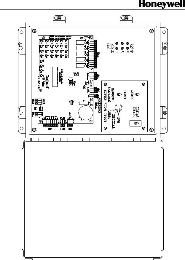
Figure 1-1: Model SGC-60 Master Controller
SG-60 High Intensity Strobe System |
1-2 |
Manual EPM-00000019 Rev A |

Airport Systems
Figure 1-2: Model SGF-60 Flashhead |
SG-60 High Intensity Strobe System |
1-3 |
Manual EPM-00000019 Rev A |

Airport Systems
1.3Safety Precautions
The following general safety precautions must be observed during all phases of operation, service, and repair of this equipment. Failure to comply with these precautions or with specific warnings elsewhere in this manual violates safety standards of design, manufacture, and intended use of this equipment. Honeywell assumes no liability for the customer’s failure to comply with these requirements, as listed below.
1.Any interruption of the protective grounding conductor (inside or outside the instrument) or disconnecting the protective earth ground terminal is likely to make this equipment dangerous. Intentional interruption is prohibited.
2.Whenever it is likely that the ground protection has been impaired, the equipment must be made inoperative by removing AC line power, and then shall be secured against any unintended operation.
3.Ensure that only fuses with the required rated current and of the specified type (normal blow, time delay, etc.) are used for replacement. The use of repaired fuses and the short-circuiting of fuseholders must be avoided.
4.Electrical energy available at many points may result in personal injury or death if touched. Any adjustment, maintenance, and repair of the opened equipment while power is applied shall be avoided as much as possible, however some maintenance described in this manual is performed with power supplied to the equipment while protective covers are removed. When repair with power applied is unavoidable, maintenance shall be carried out only by a skilled person who is aware of the hazard involved. Do not attempt internal service or adjustment unless another person, capable of rendering first aid and resuscitation, is present.
5.Do not install substitute parts or perform any unauthorized modification to the equipment.
6.Capacitors inside the equipment may still be charged after the equipment has been disconnected from its power source, even though the equipment was designed to drain charge from the capacitors when power is removed. Do not put hands or tools in the Flashhead until the High Voltage Indicator neon lamp DS1 on the High Voltage & Trigger board is extinguished. (Refer to Figure 1-2, Page 1-3, for the location of High Voltage Indicator DS1 - do not confuse the High
Voltage Indicator DS1, with the PWR ON lamp DS1.) Note that it is possible for the High Voltage Indicator DS1 to be lit even when the PWR ON lamp DS1 is off. If this happens, the energy storage capacitors C1 - C3 must be discharged before performing maintenance.
SG-60 High Intensity Strobe System |
1-4 |
Manual EPM-00000019 Rev A |
Airport Systems
WARNING!
This system uses lethal voltages in the Flashhead. Unless absolutely necessary, do not attempt to service or adjust the equipment with AC line power applied.
Safety interlock switches are provided in the Flashhead enclosure to interrupt main AC power to the power supply. These interlock switches are activated when the Flashhead door is opened in a conventional manner. No interlock is provided when other means of access are used. Never tamper with (remove, short circuit) the interlocks in any way.
AC LINE VOLTAGE IS STILL PRESENT WHEN INTERLOCKS ARE ACTIVATED. DISCONNECT POWER AT THE MAIN AC CIRCUIT BREAKERS BEFORE INSPECTING OR SERVICING, UNLESS ABSOLUTELY NECESSARY TO PERFORM MAINTENANCE WITH POWER ON.
WARNING!
Flashtubes in this lighting containing some ultraviolet permanent eye damage.
system produce brilliant flashes of light radiation that can cause temporary or
DO NOT LOOK DIRECTLY AT THE FLASHHEAD WHILE IT IS IN OPERATION.
SG-60 High Intensity Strobe System |
1-5 |
Manual EPM-00000019 Rev A |

Airport Systems
1.4 |
Specifications |
|
|
|
Light Output: |
|
|
|
|
|
Day Intensity.............................................. |
|
270,000 ±25% effective candelas, single flash |
|
|
Twilight Intensity.......................................... |
|
20,000 ±25% effective candelas, single flash |
|
|
Night Intensity......................................... |
|
2,000 ±25% effective candelas, burst of flashes |
|
|
Beam Pattern............................................................... |
|
|
120º horizontally, 3 º min. vertically |
|
|
|
|
max. intensity of 3% of peak at -10º |
|
Flash Rate: Day......................................................................... |
|
|
40 fpm - single white flash |
|
Twilight.................................................................. |
|
|
40 fpm - single white flash |
|
Night................................................................ |
|
|
40 fpm - white burst of flashes |
|
Master/Slave Operation ........ |
|
Up to 24 slave SGF-60 Flashheads may share a common |
|
|
|
sync and photocell circuit from one SGC-60 Master Controller. |
||
Electrical Input: |
|
|
|
|
|
Master Controller...................... |
|
50 Watts. 120, 208, 240, 277, 380, 480 VAC. 50, 60Hz |
|
|
Flashhead............................... |
|
500 Watts. 120, 208, 240, 277, 380, 480 VAC. 50, 60Hz |
|
|
|
|
Requires specific voltage selector block and manual |
|
|
|
|
change to transformer wiring for different AC voltages. |
|
Mechanical Properties: |
|
|
|
|
|
Flashhead |
|
|
|
|
Weight........................................................................................... |
|
|
82 pounds (37.2 kg) |
|
Dimensions............. |
18.88"w (479.4mm) x 15.25"h (387.4mm) x 10.75"d (273.1mm) |
||
|
Surface Area....................................................................................... |
|
|
1.89 square feet |
|
Wind Load .............................................................. |
|
|
100 pounds at 150 mph (240kph) |
|
Master Controller |
|
|
|
|
Weight ……………………………………………………… |
|
........24 pounds (10.89 kg) |
|
|
Dimensions ....................................... |
|
14"w (356mm) x 12"h (305mm) x 6"d (152mm) |
|
Operating Environment: |
|
|
|
|
|
Operating Temperature.............................................................................. |
|
|
-55ºC to +55ºC |
|
Humidity............................................................................................. |
|
|
95% relative humidity |
System Operating Status Indicators: |
|
|||
|
Flashhead, AC line power present ............................................... |
PWR ON Indicator DS1 |
||
|
Flashhead, high voltage present on capacitors .................... |
High Voltage Indicator DS1 |
||
|
(located on Trigger / High Voltage board) |
|
||
|
Master Controller Indicators |
|
|
|
|
Flashhead Status .......................................................... |
|
|
LEDs DS1 - DS24, red/green |
|
Day Mode .............................................................................................. |
|
|
LED DS25 red |
|
Twilight Mode ........................................................................................ |
|
|
LED DS26 red |
|
Night Mode ............................................................................................ |
|
|
LED DS27 red |
SG-60 High Intensity Strobe System |
1-6 |
Manual EPM-00000019 Rev A |
||

Airport Systems
Flashhead Fail......................................... |
Relay K1 de-energized and LED DS29 Off |
Photocell Fail.......................................... |
Relay K2 de-energized and LED DS30 Off |
Power Fail................................................ |
Relay K3 de-energized and LED DS31 Off |
Night Mode Operation............................. |
Relay K4 de-energized and LED DS32 Off |
White Night Backup (Dual Systems) ........... |
Relay K5 energized and LED DS33 On |
SG-60 High Intensity Strobe System |
1-7 |
Manual EPM-00000019 Rev A |

Airport Systems
SECTION 2. INSTALLATION & POWER UP
WARNING!
Modifications to the Power Supply are required for certain applications. Remove input power at circuit breakers and discharge capacitors with an approved grounding rod before attempting any necessary modifications.
2.1Unpacking
Carefully unpack each item and remove any internal packing material from the master controller, and the flashhead/power supply. Carefully check the supplied materials with the High Intensity Lighting System bill of materials. There are many small items that should be supplied inside clear plastic bags, verify each of these bags contain the proper amount of parts per the bill of materials. Report any shortages of materials immediately to the Honeywell Technical Support.
Examine each item for obvious physical damage. Report any claims to the carrier immediately. Pertinent data such as installation drawings, schematics, interconnection drawings, and operation manuals are included in the Master Controller carton. The flashtubes are packaged separately inside each Flashhead carton. Do not remove flashtubes from their boxes until you are ready to install them.
2.2System Configuration
Honeywell pre-configures the system to match the installation. However, there are cases where complete installation information is not available prior to the system leaving the factory or the installation has changed. Setting the configuration may also be necessary when replacing individual units in the system. The following is a guide for configuring the Master Controller and the Flashheads.
2.2.1Master Controller Configuration
There are a number of system control switches and configuration switch blocks (DIP switches) on the Master Controller. The configuration switch blocks may have multiple switches. Reference to the individual switches will be made by referring to the switch block number followed by the number of the individual switch as labeled on the switch block. For example, SW1 (Figure 2-10, Item 1, Page 2-25) has 5 individual switches. The third switch from the left is labeled as #3 on the switch block and will be referred to as SW1-3.
SG-60 High Intensity Strobe System |
2-1 |
Manual EPM-00000019 Rev A |

Airport Systems
2.2.1.1 |
System Controls |
|
Set Master Controller switches (Figure 1-1, Page 1-2) as follows: |
|
|
POWER SWITCH -------------------------------------------------------------------------- |
OFF |
|
LOCAL / REMOTE Switch ------------------------------------------------------------ |
LOCAL |
|
MODE Switch ------------------------------------------------------------------------------- |
DAY |
|
The Master Controller has the following control switches (Figure 1-1, Page 1-2):
∙POWER SWITCH: Toggle switch that turns input AC line power on/off in the Master Controller. Does not affect AC power to the Flashheads. Input voltage is present at terminal block PB1, even with the power switch turned off.
∙RESET Switch: Momentary pushbutton that resets the Master Controller. Switch must be held for about one second to activate.
∙REMOTE / LOCAL Mode Switch: Two-position toggle switch that permits manual
(local) selection of the flash intensity level using the DAY / TWILIGHT / NIGHT rotary switch. In normal (remote) operation, permits automatic operation controlled by the Ambient Light Sensor photocell.
∙DAY / TWILIGHT / NIGHT Switch: Three-position rotary switch that allows manual selection of three light intensities of the system (DAY = high, TWILIGHT = intermediate, and NIGHT = low). The REMOTE / LOCAL Mode Switch must be in the LOCAL position to use this switch.
2.2.1.2Power Configuration
The input voltage selection is set at the factory prior to shipping. The user shall verify the correct voltage as indicated by the label by Power In terminal block PB1 (Figure
1-1, Page1-2). If the voltage listed on the label does not match the voltage at the site, contact Tech Support at (805) 581-5591.
2.2.1.3Configuration Switches
∙SW1 – (Figure 2-10, Item 1, Page 2-25). This switch is used to set the number of Flashheads (including antenna obstruction light (AOL)) in the system up to 24. If the switches are set for more than 24 the system will still monitor only 24 Flashheads. The number of lights configured equals the sum of all the switches set to ON (positive binary). For example, to configure for 10 Flashheads, set SW1-4 (8 lights) to ON and SW1-2 (2 lights) to ON for a total of 10 (8+2) lights.
§SW1-1 – Set to ON (up) for 1 light
§SW1-2 – Set to ON (up) for 2 lights
§SW1-3 – Set to ON (up) for 4 lights
§SW1-4 – Set to ON (up) for 8 lights
§SW1-5 – Set to ON (up) for 16 lights
SG-60 High Intensity Strobe System |
2-2 |
Manual EPM-00000019 Rev A |

Airport Systems
∙SW2 – (Figure 2-10, Item 2, Page 2-25) This switch is used to set for Catenary operation (suspended cable warning lights) and for Dual systems (Red lights at night, and white strobes during the day).
§SW2-1 – Set to ON (up) for Catenary system.
§SW2-2 – Set to ON (up) for Dual system.
§SW2-3 – Set to OFF (down). Reserved for future use.
∙SW3 – (Figure 2-10, Item 8, Page 2-25) This switch is used to set the termination resistor for the communications line.
§SW3-1 – Set to ON if the Master Controller is at the end of the communications line. In a typical installation, the communications lines are terminated at the Master Controller and at the top level of Flashheads. In this case, this switch should be set ON.
2.2.2Flashhead Configuration
All of the configuration for the Flashhead in done on the digital controller board. Because of the high voltage present in the Flashhead, there are interlock switches and fuses as follows (Figure 1-2, Page 1-3):
∙S1 POWER Interlock Switch: Three-position push/pull switch. When the Flashhead door is opened, S1 interrupts AC line power to transformers T1 and
T2 when using 120VAC single-phase power. (When using 2-phase AC power, S1 does not interrupt AC power to transformers T1 and T2.) When the Flashhead door is opened, the PWR ON lamp DS1 to turn off. Also interrupts power to relay K1, causing the high voltage to be shut off and the energy storage capacitors to discharge. When door is open and S1 is pulled out manually, the interlock is defeated, which allows the Flashhead to operate under power.
∙S2 MODE Interlock Switch: Three-position push/pull switch. When the Flashhead door is opened, transfers flash intensity mode select from remote control (by SGC-60 Master Controller) to local control using switch S3. When door is open and S2 is pulled out manually, the interlock is defeated, which allows the Flashhead to operate under remote mode control.
∙S3 MODE TEST Switch: Three-position rotary switch allows local flash intensity mode selection (Day, Twilight or Night) for the individual Flashhead, while not affecting the operation of any other Flashhead in the system.
∙F1 Main Power Line Fuse: Provides protection for AC power to transformer T1.
Value varies with input AC line voltage. Refer to Section 7.0 for the correct fuse values. Honeywell provides the correct fuse for the supplied power configuration.
∙F2 Logic Power Line Fuse: Provides protection for the AC power to the logic transformer T2. Value varies with input line voltage. Refer to Section 7.0 for the correct fuse values. Honeywell provides the correct fuse for the supplied power configuration.
SG-60 High Intensity Strobe System |
2-3 |
Manual EPM-00000019 Rev A |

Airport Systems
2.2.2.1Power Configuration
The Flashhead(s) are factory set for the correct AC input line voltage. However, the user shall verify that the AC line voltage selector block (located on the transformer board on top of transformer T1, Figure 1-2, Page 1-3) is labeled with the correct AC line voltage used at the site. For example, voltage selector block part number 77-3319 is labeled for 120VAC. If the voltage selector block is not labeled for the correct AC line voltage used at the site, the correct voltage selector block must be obtained from Honeywell, and the AC input wiring to transformer T2 must also be verified and corrected if necessary according to Figure 3-2, Page 3-12.
2.2.2.2Configuration Switches
∙SW1 – (Figure 2-11, Item 2, Page 2-26) This switch is used to reset the processor
§Press and hold – resets the processor and tests the automatic power reset circuit. Press and hold SW1 until the 5v power indicator (DS1, Figure 2-11, Item 1, Page 2-26) turns OFF momentarily then release.
∙SW2 – (Figure 2-11, Item 4, Page 2-26) This switch is used to set special operation options. Set all four switches to OFF unless your system meets one of the two conditions below:
CONDITION 1: You have a Catenary System
§SW2-1 – Set ON for all Flashheads on top level of a Catenary installation.
§SW2-2 – Set ON for all Flashheads on bottom level of Catenary installation.
§SW2 -1 & -2 – Set both to ON for all Flashheads on middle level of a Catenary installation.
CONDITION 2: You have Dual (Red/White) system with an older-model Master Controller.
§SW2-3 – Set to ON. This is provided for backward compatibility with older installations only. For new installations this switch is always OFF. For older white-only installations this switch is also OFF.
To determine if an existing installation has an older Master Controller, refer to the new Master Controller in Figure 2-10, Page 2-25. Older Master Controllers do not have terminals TB5-TB9, or an EXT RED switch
SW2-2 (Item 2 in the figure).
Note: Switch SW2-4 is a spare reserved for future use.
SG-60 High Intensity Strobe System |
2-4 |
Manual EPM-00000019 Rev A |

Airport Systems
∙SW3 – (Figure 2-11, Item 3, Page 2-26) Used to specify the ID number for the Flashhead. Each Flashhead must be set with a unique ID number as indicated on the installation drawings. There is a diagram next to the switch showing the values for the switch. The ID number is the total of the values of the switches set to OFF (negative binary). For example, to set ID #10, set SW3-2 (value 2) OFF (down) and SW3-4 (value 8) OFF (down) for a total of
10 (2+8).
§SW3-1 – Set to OFF (down) for value 1
§SW3-2 – Set to OFF (down) for value 2
§SW3-3 – Set to OFF (down) for value 4
§SW3-4 – Set to OFF (down) for value 8
§SW3-5 – Set to OFF (down) for value 16
∙SW4 – (Figure 2-11, Item 5, Page 2-26) This is used for the terminating resistor on the communications line.
§SW4-1 – Set to ON (up) for terminating resistor. This should be set ON only for the Flashhead where the communication lines are terminated. In a typical installation, the communications lines are terminated at the Master Controller and the upper most Flashhead. In systems with an
AOL, the AOL is typically the upper most Flashhead. In systems without an AOL, any one but only one of the Flashheads at the top level can be set to ON. For all others, set to OFF. If the system is being installed in stages as the tower is erected, SW4-1 should be set ON for one of the flashheads at the highest installed level. As additional flashheads are added at higher levels, adjust the configuration by setting SW4-1 to OFF in the previous flashhead and set SW4-1 to ON for one of the flashheads at the highest installed level.
2.2.2.3Flashtube Installation
The Flashheads are shipped from the factory without the flashtubes installed to prevent damage during shipping. Install the flashtubes per the following procedure:
1.If Flashhead is already wired to AC power: Shut off the power to the system by opening the main AC power circuit breakers.
2.Release the Flashhead cover latches.
3.Swing the cover open, exercising caution not to damage the glass face or the gasket.
4.Unpack the flashtube. Do not touch the glass envelope - contamination from a fingerprint will degrade the reliability of the flashtube.
5.Holding the flashtube by its metal ends, center it in the reflector assembly and snap it into place. Make sure the red mark on the flashtube matches the red mark on the socket assembly.
6.Attach the fast-on connector at each end of the flashtube to each socket assembly. Make sure wires are not twisted - the metal to glass bond is fragile.
SG-60 High Intensity Strobe System |
2-5 |
Manual EPM-00000019 Rev A |
Airport Systems
7.Refer to Figure 2-1 below. Dress the electrode wires away from the sides of the reflector.
8.Close and fasten the Flashhead cover.
Figure 2-1: Flashtube Installation
2.3Installation
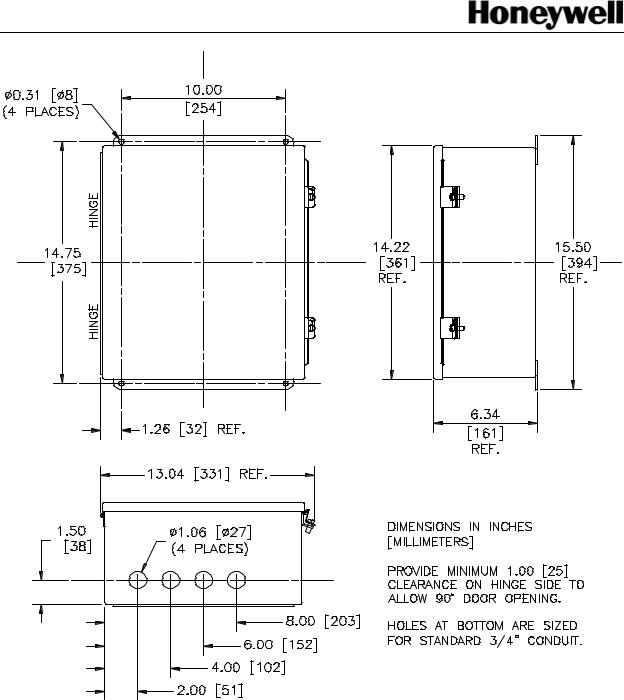
2.3.1SGC-60 Master Controller
The Master Controller is connected to Flashheads via the data communications cable provided by Honeywell. The length of this cable (up to 2500 feet) determines how far the Master Controller can be mounted from the Flashheads.
A detailed drawing for mounting the Master Controller is shown in Figure 2-2, Page 2-9
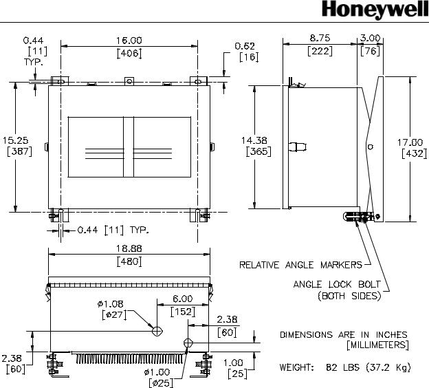
2.3.2SGF-60 Flashhead
Normally the Flashheads are mounted at the uppermost point and additional referenced elevations on the structure. The Flashhead is connected to its Master Controller via the data communications cable provided by Honeywell. The length of this cable (up to 2500 feet) determines how far any Flashhead can be mounted from the Master Controller.
Honeywell labels all the Flashheads with numbers ranging from 1 to 24 depending on the number of required lights for the structure. Typically, the upper most level of lights will contain the lights with numbers 1 through 3 or 4. If the structure has an appurtenance of greater that 40 feet, an AOL (Antenna Obstruction Light) is required and it will have a Flashhead Number of 1. The High Intensity Flashheads will start with
Flashhead Number 2. The flashheads should continue down the tower from the top sequentially ending with the highest number at the bottom level.
The vent hole on the bottom surface of the power supply is covered with a solid plug prior to shipping. Optional screened plugs are furnished separately.
SG-60 High Intensity Strobe System |
2-6 |
Manual EPM-00000019 Rev A |

Airport Systems
Typically, the Flashhead is mounted to a bracket, which is then attached to the structure. Honeywell can supply brackets for most types of installations.
A detailed drawing for mounting the Flashhead is shown in Figure 2-3, Page 2-10.
2.3.2.1Setting the Flashhead Elevation
Flashheads must be mounted at the proper vertical angle to assure proper light output.
Depending on the elevation of the light level, the Flashhead may need to be adjusted to reduce the amount of ground scatter. Please refer to the table below for proper elevation for the lights.
1.Slightly loosen the angle lock bolts, which are at the bottom of the mounting arms (see Figure 2-3, Page 2-10). The bolt heads and nuts fit 7/16" wrenches or nut drivers (tightening will require a pair of tools).
2.Adjust the Flashhead enclosure until the bubble indicator on top of the enclosure reads level.
3.Take note of the position of the bolt with respect to the silk-screened markings on the angle indicator. This position is the zero degree position. The markings are screened at intervals of one degree.
4.Adjust the Flashhead enclosure to aim the beam upward until the bolt head has shifted by the number of degrees indicated in the table below.
5.Securely tighten both angle lock bolts.
Light Unit Elevation Above the Horizontal
Height of Light Unit Above |
Degrees of Elevation above |
Ground Level |
Horizontal |
More than 500 feet |
0° |
401 feet to 500 feet |
1° |
301 feet to 400 feet |
2° |
Less than 300 feet |
3° |
2.3.3Ambient Light Sensor (Photocell)
The Ambient Light Sensor, when supplied with the system, shall be mounted upright, away from artificial light (e.g. floodlights), and in a location that will enable the sensor window to have an unobstructed view of the polar sky (pointed north in the northern hemisphere, not pointed toward the sun). The photocell housing wire entry is tapped to allow mounting to 1/2" threaded pipe. Conduit and related hardware will be supplied by the customer. A 21-foot 3-conductor cable is attached to the photocell for remote installation.
SG-60 High Intensity Strobe System |
2-7 |
Manual EPM-00000019 Rev A |

Airport Systems
2.3.4Cables and Junction Boxes
The cables shall be properly supported and terminated in the junction boxes per the detailed description provided in section 2.4, page 2-11 of this document. Additional information regarding cables and junction box installation can be found on the drawing set for the lighting system. Particular attention should be paid to assure that the data cable shields are isolated from the junction box housings.
SG-60 High Intensity Strobe System |
2-8 |
Manual EPM-00000019 Rev A |
Airport Systems
Figure 2-2: Master Controller Mounting Dimensions
SG-60 High Intensity Strobe System |
2-9 |
Manual EPM-00000019 Rev A |
Airport Systems
Figure 2-3: Flashhead Outline and Mounting Dimensions
SG-60 High Intensity Strobe System |
2-10 |
Manual EPM-00000019 Rev A |
 Loading...