


 Loading...
S8910U3000
UNIVERSAL HOT SURFACE IGNITION MODULE
INSTALLATION INSTRUCTIONS
Installation of this product must be performed by a trained and qualified service technician.
APPLICATION
The S8910U Universal Hot Surface Ignition Module is designed to provide easy field replacement for a wide range of hot surface ignition modules manufactured by Honeywell, Robertshaw and White-Rodgers. The S8910U Module provides operating control of a direct ignition system using a 120 Vac hot surface igniter. The S8910U replaces existing flame rectification type hot surface ignition modules with the following characteristics:
•120 Vac (up to 5A) timed warmup hot surface ignition elements.
•Single rod (local sense) or dual rod (remote sense) hot surface ignition.
•One or three ignition trials per call for heat.
•Four-second or seven-second ignition trials.
•Prepurge of 32 seconds or less.
•Up to 96 seconds between trial purge times (three-trial mode only).
•Natural or LP gas.
The S8910U is not designed to replace:
•Intermittent pilot ignition controls.
•Direct spark ignition controls.
•Proven 120 Vac hot surface ignition controls.
•24 Vac element hot surface ignition controls.
•240 Vac input/120 Vac element hot surface ignition controls.
•120 Vac timed warmup hot surface ignition controls
—Ignition trial time shorter than four seconds.
—Ignition trial time longer than twelve seconds.
—Edge connectors rather than male quick-connects.
The S8910U package contains the S8910U control, and easy- to-use instructions, and the accessories required to adapt the existing hot surface ignition module. The accessory bag assembly includes the White-Rodgers adapter, Robertshaw ground lead, four 1/4 in. female .032 quick-connects, one 3/16 in. female .032 quick-connect, and nine wire labels. The wiring labels are included to assure proper marking of the wires attached to the existing module.
A complete list of the specific Honeywell and other modules that the S8910U is designed to replace is provided in Tables 1 through 3.
NOTE: The S8910U is intended to replace only defective ignition controls. The service technician should make sure that the other parts of the appliance and control system operate safely and reliably before replacing the ignition control.
WARNING
EXPLOSION HAZARD. CAN CAUSE INJURY OR EQUIPMENT DAMAGE.
The S8910U can only be used for direct replacement. Check Tables 1 through 3 before replacing an existing hot surface module with the S8910U. If the existing module is not listed, do not use the S8910U to replace it. Always refer to the cross-reference table for proper DIP switch settings.
Electrical Ratings:
Control Voltage: 24 V, 60 Hz. Maximum Valve Contact Rating: 2 A. Current Draw: 0.4 A plus valve load.
Hot Surface Igniter Voltage: 120 Vac, 60 Hz. Contact Rating at 120 Vac: 5 A.
IMPORTANT
The S8910U is designed for 60 Hz applications. Timings change by 20 percent in 50 Hz applications.
Hot Surface Igniter or Igniter-Sensor:
Norton Model 201 or 271 or equivalent.
NOTE: If an igniter other than a Norton Model 201 or 271 is used, the igniter must meet the following minimum specifications required over the life of the igniter:
•Igniter must reach 1832 °F (1000 °C) within the selected warm up time of 7, 17, 34 or 45 seconds with 102 Vac applied.
•Igniter must maintain at least 500M ohm insulation resistance between the igniter leadwires and the igniter mounting bracket.
•Igniter must not develop an insulating layer on its surface (over time) that would prevent flame sensing.
•Igniter surface area immersed in flame must not exceed one-fourth of the grounded area immersed in flame. This would prevent flame sensing.
34-00008EFS-01
S8910U3000
•Igniter current draw at 132 Vac must not exceed 5A.
Sensor:
Separate sensor required for remote sensing applications.
Wiring:
Use existing appliance wiring. If repair or replacement of leadwires is required, follow instructions on appliance label. Use included quick connect terminals and wiring adaptors according to instructions.
Prepurge:
32 seconds.
Igniter Warmup:
7 (12), 17 (27), 34 or 45 seconds. Numbers in parenthesis represent second and third trial for ignition timings.
Purge between Trials for Ignition:
96 seconds (32 second prepurge and 64 seconds interpurge).
Flame Failure Response Time:
1.5 seconds maximum.
Ignition Sequence:
The number of trials for ignition and trial time are determined by selectable DIP switches.
Ambient Operating Temperature:
-40 to +175 °F (-40 to +79 °C).
Accessory Kit (Included):
•White-Rodgers adapter.
•Robertshaw ground lead.
•Four 1/4 in. female .032 quick-connects.
•One 3/16 in. female .032 quick-connect.
•Nine wire labels.
Approvals:
IAS Design Certified: Certification Report No. C2027002.
IMPORTANT
The specifications given in this publication do not include normal manufacturing tolerances. Therefore, this unit may not exactly match the listed specifications. Also, this product is tested and calibrated under closely controlled conditions, and some minor differences in performance can be expected if those conditions are changed.
The S8910U package contains the S8910U control, and easy- to-use instructions, plus the accessories required to adapt the existing hot surface ignition module. The accessory bag assembly includes the White-Rodgers adapter, Robertshaw ground lead, four 1/4 in. female .032 quick-connects, one 3/16 in. female .032 quick-connects, and nine wiring labels. The wiring labels are included to assure proper marking of the wires attached to the existing module.
A complete listing of the specific Honeywell and other modules that the S8910U is designed to replace is provided in Tables 1 through 3.
NOTE: The S8910U is intended to replace only defective ignition controls. The service technician should make sure that the other parts of the appliance and control system operate safely and reliably before replacing the ignition control.
Model Available:
S8910U Universal Hot Surface Ignition Module.
ORDERING INFORMATION
When purchasing replacement and modernization products from your TRADELINE® wholesaler or distributor, refer to the TRADELINE® Catalog or price sheets for complete ordering number. If you have additional questions, need further information, or would like to comment on our products or services, please write or phone:
1.Your local Honeywell Environmental and Combustion Controls Sales Office (check white pages of your phone directory).
2.Honeywell Customer Care 1985 Douglas Drive North
Minneapolis, Minnesota 55422-4386
3.http://customer.honeywell.com or http://customer.honeywell.ca
International Sales and Service Offices in all principal cities of the world. Manufacturing in Belgium, Canada, China, Czech Republic, Germany, Hungary, Italy, Mexico, Netherlands, United Kingdom, and United States.
34-00008EFS—01 |
2 |
S8910U3000
Table 1. White-Rodgers Control to Honeywell S8910U Cross Reference.
NOTES: This list is for reference only. Honeywell reserves the right to add or delete models at any time, based on new or updated information.
|
S8910U |
|
|
|
|
|
|
|
|
|
|
|
|
|
|
|
Remove |
|
|
|
|
|
|
|
Black |
Local (L) or |
Lockout |
|
|
Igniter |
Between |
|
Jumper |
Remote (R) |
Time |
Ignition |
PrePurge |
Warmup |
Trial Purge |
Model Numbers |
|
Sensing |
(sec) |
Trials |
(sec) |
(sec) |
(sec) |
|
|
|
|
|
|
|
|
S8910U |
— |
Local or |
4 |
1 |
32 |
34 |
NA |
Specifications |
|
Remote |
|
|
|
|
|
|
|
3 |
|
|
96 |
||
|
|
|
|
|
|
||
|
|
|
|
|
|
|
|
|
|
|
7 |
1 |
|
|
NA |
|
|
|
|
|
|
|
|
|
|
|
|
3 |
|
|
96 |
|
|
|
|
|
|
|
|
50E47-1 thru 9 |
Yes |
R |
4 |
1 |
0 |
17 |
NA |
|
|
|
|
|
|
|
|
50E47-10 thru 19 |
Yes |
R |
4 |
1 |
0 |
45 |
NA |
|
|
|
|
|
|
|
|
50E47-20 thru 29 |
Yes |
R |
4 |
1 |
30 |
17 |
NA |
|
|
|
|
|
|
|
|
50E47-30 thru 39 |
Yes |
R |
4 |
1 |
30 |
45 |
NA |
|
|
|
|
|
|
|
|
50E47-40 thru 49 |
Yes |
R |
4 |
3 |
30 |
17 |
90 |
|
|
|
|
|
|
|
|
50E47-50 thru 59 |
Yes |
R |
4 |
3 |
30 |
45 |
90 |
|
|
|
|
|
|
|
|
50E47-60 thru 69 |
Yes |
R |
4 |
3 |
0 |
17 |
60 |
|
|
|
|
|
|
|
|
50E47-70 thru 79 |
Yes |
R |
4 |
3 |
0 |
45 |
60 |
|
|
|
|
|
|
|
|
50E47-101 thru 109 |
Yes |
R |
7 |
1 |
0 |
17 |
NA |
|
|
|
|
|
|
|
|
50E47-110 thru 119 |
Yes |
R |
7 |
1 |
0 |
45 |
NA |
|
|
|
|
|
|
|
|
50E47-120 thru 129 |
Yes |
R |
7 |
1 |
30 |
17 |
NA |
|
|
|
|
|
|
|
|
50E47-130 thru 139 |
Yes |
R |
7 |
1 |
30 |
45 |
NA |
|
|
|
|
|
|
|
|
50E47-140 thru 149 |
Yes |
R |
7 |
3 |
30 |
17 |
90 |
|
|
|
|
|
|
|
|
50E47-150 thru 159 |
Yes |
R |
7 |
3 |
30 |
45 |
90 |
|
|
|
|
|
|
|
|
50E47-160 thru 169 |
Yes |
R |
7 |
3 |
0 |
17 |
60 |
|
|
|
|
|
|
|
|
50E47-170 thru 179 |
Yes |
R |
7 |
3 |
0 |
45 |
60 |
|
|
|
|
|
|
|
|
50E47-201 thru 209 |
Yes |
R |
4 |
1 |
0 |
17 |
NA |
|
|
|
|
|
|
|
|
50E47-210 thru 219 |
Yes |
R |
4 |
1 |
0 |
45 |
NA |
|
|
|
|
|
|
|
|
50E47-220 thru 229 |
Yes |
R |
4 |
1 |
30 |
17 |
NA |
|
|
|
|
|
|
|
|
50E47-230 thru 239 |
Yes |
R |
4 |
1 |
30 |
45 |
NA |
|
|
|
|
|
|
|
|
50E47-240 thru 249 |
Yes |
R |
4 |
3 |
30 |
17 |
90 |
|
|
|
|
|
|
|
|
50E47-250 thru 259 |
Yes |
R |
4 |
3 |
30 |
45 |
90 |
|
|
|
|
|
|
|
|
50E47-260 thru 269 |
Yes |
R |
4 |
3 |
0 |
17 |
60 |
|
|
|
|
|
|
|
|
50E47-270 thru 279 |
Yes |
R |
4 |
3 |
0 |
45 |
60 |
|
|
|
|
|
|
|
|
50E47-301 thru 309 |
Yes |
R |
7 |
1 |
0 |
17 |
NA |
|
|
|
|
|
|
|
|
50E47-310 thru 319 |
Yes |
R |
7 |
1 |
0 |
45 |
NA |
|
|
|
|
|
|
|
|
50E47-320 thru 329 |
Yes |
R |
7 |
1 |
30 |
17 |
NA |
|
|
|
|
|
|
|
|
50E47-330 thru 339 |
Yes |
R |
7 |
1 |
30 |
45 |
NA |
|
|
|
|
|
|
|
|
50E47-340 thru 349 |
Yes |
R |
7 |
3 |
30 |
17 |
90 |
|
|
|
|
|
|
|
|
50E47-350 thru 359 |
Yes |
R |
7 |
3 |
30 |
45 |
90 |
|
|
|
|
|
|
|
|
50E47-360 thru 369 |
Yes |
R |
7 |
3 |
0 |
17 |
60 |
|
|
|
|
|
|
|
|
50E47-370 thru 379 |
Yes |
R |
7 |
3 |
0 |
45 |
60 |
|
|
|
|
|
|
|
|
50F47-1 thru 9 |
Yes |
R |
4 |
1 |
0 |
17 |
NA |
|
|
|
|
|
|
|
|
50F47-10 thru 19 |
Yes |
R |
4 |
1 |
0 |
45 |
NA |
|
|
|
|
|
|
|
|
50F47-20 thru 29 |
Yes |
R |
4 |
1 |
17 |
17 |
NA |
|
|
|
|
|
|
|
|
50F47-30 thru 39 |
Yes |
R |
4 |
1 |
17 |
45 |
NA |
|
|
|
|
|
|
|
|
50F47-40 thru 49 |
Yes |
R |
4 |
3 |
17 |
17 |
77 |
|
|
|
|
|
|
|
|
3 |
34-00008EFS—01 |
S8910U3000
Table 1. White-Rodgers Control to Honeywell S8910U Cross Reference. (Continued)
NOTES: This list is for reference only. Honeywell reserves the right to add or delete models at any time, based on new or updated information.
|
S8910U |
|
|
|
|
|
|
|
|
|
|
|
|
|
|
|
Remove |
|
|
|
|
|
|
|
Black |
Local (L) or |
Lockout |
|
|
Igniter |
Between |
|
Jumper |
Remote (R) |
Time |
Ignition |
PrePurge |
Warmup |
Trial Purge |
Model Numbers |
|
Sensing |
(sec) |
Trials |
(sec) |
(sec) |
(sec) |
|
|
|
|
|
|
|
|
S8910U |
— |
Local or |
4 |
1 |
32 |
34 |
NA |
Specifications |
|
Remote |
|
|
|
|
|
|
|
3 |
|
|
96 |
||
|
|
|
|
|
|
||
|
|
|
|
|
|
|
|
|
|
|
7 |
1 |
|
|
NA |
|
|
|
|
|
|
|
|
|
|
|
|
3 |
|
|
96 |
|
|
|
|
|
|
|
|
50F47-50 thru 59 |
Yes |
R |
4 |
3 |
17 |
45 |
77 |
|
|
|
|
|
|
|
|
50F47-60 thru 69 |
Yes |
R |
4 |
3 |
0 |
17 |
60 |
|
|
|
|
|
|
|
|
50F47-70 thru 79 |
Yes |
R |
4 |
3 |
0 |
45 |
60 |
|
|
|
|
|
|
|
|
50F47-101 thru 109 |
Yes |
R |
7 |
1 |
0 |
17 |
NA |
|
|
|
|
|
|
|
|
50F47-110 thru 119 |
Yes |
R |
7 |
1 |
0 |
45 |
NA |
|
|
|
|
|
|
|
|
50F47-120 thru 129 |
Yes |
R |
7 |
1 |
17 |
17 |
NA |
|
|
|
|
|
|
|
|
50F47-130 thru 139 |
Yes |
R |
7 |
1 |
17 |
45 |
NA |
|
|
|
|
|
|
|
|
50F47-140 thru 149 |
Yes |
R |
7 |
3 |
17 |
17 |
77 |
|
|
|
|
|
|
|
|
50F47-150 thru 159 |
Yes |
R |
7 |
3 |
17 |
45 |
77 |
|
|
|
|
|
|
|
|
50F47-160 thru 169 |
Yes |
R |
7 |
3 |
0 |
17 |
60 |
|
|
|
|
|
|
|
|
50F47-170 thru 179 |
Yes |
R |
7 |
3 |
0 |
45 |
60 |
|
|
|
|
|
|
|
|
50F47-201 thru 209 |
Yes |
R |
4 |
1 |
0 |
17 |
NA |
|
|
|
|
|
|
|
|
50F47-210 thru 219 |
Yes |
R |
4 |
1 |
0 |
45 |
NA |
|
|
|
|
|
|
|
|
50F47-220 thru 229 |
Yes |
R |
4 |
1 |
17 |
17 |
NA |
|
|
|
|
|
|
|
|
50F47-230 thru 239 |
Yes |
R |
4 |
1 |
17 |
45 |
NA |
|
|
|
|
|
|
|
|
50F47-240 thru 249 |
Yes |
R |
4 |
3 |
17 |
17 |
77 |
|
|
|
|
|
|
|
|
50F47-250 thru 259 |
Yes |
R |
4 |
3 |
17 |
45 |
77 |
|
|
|
|
|
|
|
|
50F47-260 thru 269 |
Yes |
R |
4 |
3 |
0 |
17 |
60 |
|
|
|
|
|
|
|
|
50F47-270 thru 279 |
Yes |
R |
4 |
3 |
0 |
45 |
60 |
|
|
|
|
|
|
|
|
50F47-301 thru 309 |
Yes |
R |
7 |
1 |
0 |
17 |
NA |
|
|
|
|
|
|
|
|
50F47-310 thru 319 |
Yes |
R |
7 |
1 |
0 |
45 |
NA |
|
|
|
|
|
|
|
|
50F47-320 thru 329 |
Yes |
R |
7 |
1 |
17 |
17 |
NA |
|
|
|
|
|
|
|
|
50F47-330 thru 339 |
Yes |
R |
7 |
1 |
17 |
45 |
NA |
|
|
|
|
|
|
|
|
50F47-340 thru 349 |
Yes |
R |
7 |
3 |
17 |
17 |
77 |
|
|
|
|
|
|
|
|
50F47-350 thru 359 |
Yes |
R |
7 |
3 |
17 |
45 |
77 |
|
|
|
|
|
|
|
|
50F47-360 thru 369 |
Yes |
R |
7 |
3 |
0 |
17 |
60 |
|
|
|
|
|
|
|
|
50F47-370 thru 379 |
Yes |
R |
7 |
3 |
0 |
45 |
60 |
|
|
|
|
|
|
|
|
34-00008EFS—01 |
4 |
S8910U3000
Table 2. Robertshaw Control to Honeywell S8910U Cross Reference.
|
S8910U |
|
|
|
|
|
|
|
|
|
|
|
|
|
|
|
Remove |
|
|
|
|
|
|
|
Black |
Local (L) or |
Lockout |
|
|
Igniter |
Between |
|
Jumper |
Remote (R) |
Time |
Ignition |
PrePurge |
Warmup |
Trial Purge |
Model Numbers |
|
Sensing |
(sec) |
Trials |
(sec) |
(sec) |
(sec) |
|
|
|
|
|
|
|
|
S8910U |
— |
Local or |
4 |
1 |
32 |
34 |
NA |
Specifications |
|
Remote |
|
|
|
|
|
|
|
3 |
|
|
96 |
||
|
|
|
|
|
|
||
|
|
|
|
|
|
|
|
|
|
|
7 |
1 |
|
|
NA |
|
|
|
|
|
|
|
|
|
|
|
|
3 |
|
|
96 |
|
|
|
|
|
|
|
|
HS780-17NL-104A |
No |
L |
4 |
1 |
0 |
17 |
NA |
|
|
|
|
|
|
|
|
HS780-17NL-108A |
No |
L |
8a |
1 |
0 |
17 |
NA |
HS780-17NL-304A |
No |
L |
4 |
3 |
0 |
17 |
17 |
|
|
|
|
|
|
|
|
HS780-17NL-308A |
No |
L |
8a |
3 |
0 |
17 |
17 |
HS780-17NR-104A |
Yes |
R |
4 |
1 |
0 |
17 |
NA |
|
|
|
|
|
|
|
|
HS780-17NR-306A |
Yes |
R |
6a |
3 |
0 |
17 |
17 |
HS780-17NR-308A |
Yes |
R |
8a |
3 |
0 |
17 |
17 |
HS780-34NL-108A |
No |
L |
8a |
1 |
0 |
34 |
NA |
HS780-34NL-304A |
No |
L |
4 |
3 |
0 |
34 |
34 |
|
|
|
|
|
|
|
|
HS780-34NL-306A |
No |
L |
6a |
3 |
0 |
34 |
34 |
HS780-34NL-308A |
No |
L |
8a |
3 |
0 |
34 |
34 |
HS780-34NL-312A |
No |
L |
12b |
3 |
0 |
34 |
34 |
HS780-34NR-104A |
Yes |
R |
4 |
1 |
0 |
34 |
NA |
|
|
|
|
|
|
|
|
HS780-34NR-306A |
Yes |
R |
6a |
3 |
0 |
34 |
34 |
HS780-34NR-308A |
Yes |
R |
8a |
3 |
0 |
34 |
34 |
HS780-34NR-312A |
Yes |
R |
12b |
3 |
0 |
34 |
34 |
HS780-34PL-308A |
No |
L |
8a |
3 |
34 |
34 |
34 |
aThe S8910U and the original control lockout times are different. The S8910U lockout time is within the design tolerance lockout time of the original control.
bThe lockout time of the S8910U is shorter than the original control. Be sure to observe the appliance operation under a variety of input conditions to assure reliable operation.
5 |
34-00008EFS—01 |
S8910U3000
Table 3. Honeywell Control to Honeywell S8910U Cross Reference.
|
S8910U |
|
|
|
|
|
|
|
|
|
|
|
|
|
|
|
Remove |
|
|
|
|
|
|
|
Black |
Local (L) or |
Lockout |
|
|
Igniter |
Between |
|
Jumper |
Remote (R) |
Time |
Ignition |
PrePurge |
Warmup |
Trial Purge |
Model Numbers |
|
Sensing |
(sec) |
Trials |
(sec) |
(sec) |
(sec) |
|
|
|
|
|
|
|
|
S8910U |
— |
Local or |
4 |
1 |
32 |
34 |
NA |
Specifications |
|
Remote |
|
|
|
|
|
|
|
3 |
|
|
96 |
||
|
|
|
|
|
|
||
|
|
|
|
|
|
|
|
|
|
|
7 |
1 |
|
|
NA |
|
|
|
|
|
|
|
|
|
|
|
|
3 |
|
|
96 |
|
|
|
|
|
|
|
|
S89C1004 |
No |
L |
6a |
1 |
0 |
34 |
NA |
S89C1012 |
No |
L |
6a |
1 |
0 |
34 |
NA |
S89C1046 |
No |
L |
4 |
1 |
0 |
34 |
NA |
|
|
|
|
|
|
|
|
S89C1087 |
No |
L |
6a |
1 |
0 |
34 |
NA |
S89C1103 |
No |
L |
4 |
1 |
0 |
34 |
NA |
|
|
|
|
|
|
|
|
S89D1002 |
Yes |
R |
6a |
1 |
0 |
34 |
NA |
S89G1005 |
No |
L |
4 |
3 |
0 |
34 |
30 |
|
|
|
|
|
|
|
|
S89G1013 |
No |
L |
6a |
3 |
0 |
34 |
30 |
S89G1021 |
No |
L |
11b |
3 |
0 |
34 |
30 |
S89G1047 |
No |
L |
6a |
3 |
0 |
34 |
30 |
S89H1003 |
Yes |
R |
4 |
3 |
0 |
34 |
30 |
|
|
|
|
|
|
|
|
S89H1011 |
Yes |
R |
6a |
3 |
0 |
34 |
30 |
S89H1029 |
Yes |
R |
11b |
3 |
0 |
34 |
30 |
S89J1008 |
No |
L |
6a |
1 |
0 |
34 |
NA |
S890C1007 |
No |
L |
6a |
1 |
30 |
34 |
NA |
S890D1006 |
Yes |
R |
6a |
1 |
30 |
34 |
NA |
S890G1003 |
No |
L |
4 |
3 |
30 |
34 |
30 |
|
|
|
|
|
|
|
|
S890G1011 |
No |
L |
6a |
3 |
30 |
34 |
30 |
S890G1029 |
No |
L |
11b |
3 |
30 |
34 |
30 |
S890G1037 |
No |
L |
6a |
3 |
30 |
34 |
30 |
S890H1002 |
Yes |
R |
4 |
3 |
30 |
34 |
30 |
|
|
|
|
|
|
|
|
S890H1010 |
Yes |
R |
6a |
3 |
30 |
34 |
30 |
S890H1028 |
Yes |
R |
11b |
3 |
30 |
34 |
30 |
aThe S8910U and the original control lockout times are different. The S8910U lockout time is within the design tolerance lockout time of the original control.
bThe lockout time of the S8910U is shorter than the original control. Be sure to observe the appliance operation under a variety of input conditions to assure reliable operation.
34-00008EFS—01 |
6 |

S8910U3000
Table 4. DIP switch configuration.
|
|
|
|
|
|
|
|
|
|
|
|
|
|
|
|
|
|
|
|
|
|
|
|
|
|
|
|
|
|
|
|
|
|
|
|
|
|
Trial count = 1 try |
|
|
1 |
|
2 |
|
|
3 |
|
|
4 |
|
|
|
|
||||||
|
ON |
|
|
|
|
|
|
|
|
|
|
|
|
|
|
|
|
|
|
|
|
|
|
|
|
|
|
|
|
|
|
|
|
|
|
|
|
|
|
|
|
|
|
|
|
|
|
|
|
|
|
|
|
|
|
|
|
|
|
|
|
|
|
|
|
|
|
|
|
|
|
|
|
|
|
|
|
|
|
|
|
|
|
|
|
|
|
|
|
|
|
|
|
|
|
|
|
|
|
|
ON |
|
|
|
2 |
|
|
3 |
|
|
4 |
|
|
|
Trial count = 3 tries |
|
|||
|
1 |
|
|
|
|
|
|
|
|
|
|
||||||||
|
|
|
|
|
|
|
|
|
|
|
|
||||||||
|
|
|
|
|
|
|
|
|
|
|
|
|
|
|
|
|
|
|
|
|
|
|
|
|
|
|
|
|
|
|
|
|
|
|
|
|
|
|
|
|
|
|
|
|
|
|
|
|
|
|
|
|
|
|
|
|
|
|
|
|
|
|
|
|
|
|
|
|
|
|
|
|
|
|
|
|
|
|
|
|
ON |
|
|
|
2 |
|
|
3 |
|
|
4 |
|
|
|
Trial for ignition period = 4 seconds |
||||
|
1 |
|
|
|
|
|
|
|
|
|
|||||||||
|
|
|
|
|
|
|
|
|
|
|
|||||||||
|
|
|
|
|
|
|
|
|
|
|
|
|
|
|
|
|
|
|
|
|
|
|
|
|
|
|
|
|
|
|
|
|
|
|
|
|
|
|
|
|
|
|
|
|
|
|
|
|
|
|
|
|
|
|
|
|
|
|
|
|
|
|
|
|
|
|
|
|
|
|
|
|
|
|
|
|
|
|
|
|
ON |
|
|
|
|
|
|
|
3 |
|
|
4 |
|
|
|
Trial for ignition period = 7 seconds |
|||
|
1 |
|
|
2 |
|
|
|
|
|
|
|
||||||||
|
|
|
|
|
|
|
|
|
|
|
|||||||||
|
|
|
|
|
|
|
|
|
|
|
|
|
|
|
|
|
|
|
|
|
|
|
|
|
|
|
|
|
|
|
|
|
|
|
|
|
|
|
|
|
|
|
|
|
|
|
|
|
|
|
|
|
|
|
|
|
|
|
|
|
|
|
|
|
|
|
|
|
|
|
|
|
|
|
|
|
|
|
|
|
ON |
|
|
|
2 |
|
|
3 |
|
|
4 |
|
|
|
Igniter warm-up time = |
34 seconds |
|||
|
1 |
|
|
|
|
|
|
|
|
|
|||||||||
|
|
|
|
|
|
|
|
|
|
|
|||||||||
|
|
|
|
|
|
|
|
|
|
|
|
|
|
|
|
|
|
|
|
|
|
|
|
|
|
|
|
|
|
|
|
|
|
|
|
|
|
|
|
|
|
|
|
|
|
|
|
|
|
|
|
|
|
|
|
|
|
|
|
|
|
|
|
|
|
|
|
|
|
|
|
|
|
|
|
|
|
|
|
|
|
|
|
|
|
|
|
|
|
|
|
|
|
|
|
|
|
|
|
|
ON |
|
|
|
|
|
|
|
|
|
|
|
|
|
|
|
|
Igniter warm-up time = |
45 seconds |
|
1 |
|
|
2 |
|
|
3 |
|
|
4 |
|
|
|
||||||
|
|
|
|
|
|
|
|
|
|
|
|||||||||
|
|
|
|
|
|
|
|
|
|
|
|
|
|
|
|
|
|
|
|
|
|
|
|
|
|
|
|
|
|
|
|
|
|
|
|
|
|
|
|
|
|
|
|
|
|
|
|
|
|
|
|
|
|
|
|
|
|
|
|
|
|
|
|
|
|
|
|
|
|
|
|
|
|
|
|
|
Igniter warm-up time = |
17 seconds |
|
|
ON |
|
|
|
|
|
|
|
|
|
|
|
4 |
|
|
|
|||
|
|
1 |
|
|
2 |
|
|
3 |
|
|
|
|
|
(27 seconds 2nd and 3rd trial) |
|||||
|
|
|
|
|
|
|
|
|
|
|
|
|
|
|
|
|
|
||
|
|
|
|
|
|
|
|
|
|
|
|
|
|
|
|
|
|
|
|
|
|
|
|
|
|
|
|
|
|
|
|
|
|
|
|
|
|
|
|
|
|
|
|
|
|
|
|
|
|
|
|
|
|
|
|
|
Igniter warm-up time = |
7 seconds |
|
|
ON |
|
|
|
|
|
|
|
|
|
|
|
|
|
|
|
|
||
|
1 |
|
|
2 |
|
|
3 |
|
|
4 |
|
|
|
||||||
|
|
|
|
|
|
|
|
|
|
|
(12 seconds 2nd and 3rd trial) |
||||||||
|
|
|
|
|
|
|
|
|
|
|
|
|
|
|
|
|
|
||
|
|
|
|
|
|
|
|
|
|
|
|
|
|
|
|
|
|
||
|
|
|
|
|
|
|
|
|
|
|
|
|
|
M35557 |
|
|
|||
|
|
|
|
|
|
|
|
|
|
|
|
|
|
|
|
|
|
|
|
REVIEW THE INSTALLATION
WARNING
FIRE OR EXPLOSION HAZARD.
CAN CAUSE PROPERTY DAMAGE, SEVERE INJURY, OR DEATH.
Follow these warnings exactly:
1.Review the installation as outlined in this section.
2.Plan for frequent maintenance as described in the Maintenance section.
When hot surface ignition systems are used on central heating equipment in barns, greenhouses, and commercial properties and on heating appliances such as commercial cookers, agricultural equipment, industrial heating equipment and pool heaters, heavy demands are made on the controls. Special steps may be required to prevent nuisance shut-downs and control failure due to frequent cycling, and severe environmental conditions related to moisture, corrosive chemicals, dust or excessive heat. These applications require Honeywell Home and Building Control Engineering review; contact your Honeywell Sales Representative for assistance.
Review the following conditions that can apply to your specific installation and take the precautionary steps suggested.
Frequent Cycling
These controls are designed for use on appliances that typically cycle only three to four times an hour during the heating season. In year-around applications with greater cycling rates, the control can wear out more quickly. Perform a monthly checkout.
Water or Steam Cleaning
If a module or gas control gets wet, replace it. If the appliance is likely to be cleaned with water or steam, cover the controls and wiring to protect from water or steam flow. Mount the controls high enough above the bottom of the cabinet to avoid getting wet during normal cleaning procedures. A NEMA 4 enclosure is recommended for the ignition module.
High Humidity or Dripping Water
Dripping water can cause the module to fail. Never install an appliance where water can drip on the controls.
In addition, high ambient humidity can cause the gas control to corrode and fail.
If the appliance is in a humid atmosphere, make sure air circulation around the controls is adequate to prevent condensation. Also, regularly check out the system. A NEMA 4 enclosure is recommended for the ignition module.
Corrosive Chemicals
Corrosive chemicals can attack the module and gas control, eventually causing a failure. If chemicals are used for routine cleaning, avoid contact with the controls. Where chemicals are suspended in air, as in some industrial or agricultural applications, A NEMA 4 enclosure is recommended for the ignition module.
Dust or Grease Accumulation
Heavy accumulations of dust or grease can cause controls to malfunction. Where dust or grease can be a problem, provide covers for the module and the gas control to limit contamination. A NEMA 4 enclosure is recommended for the ignition module.
7 |
34-00008EFS—01 |

S8910U3000
Heat
Excessively high temperatures can damage controls. Make sure the maximum ambient temperature at the control does not exceed the rating of the control. If the appliance operates at very high temperatures, use insulation, shielding, and air circulation, as necessary, to protect the controls. Proper insulation or shielding should be provided by the appliance manufacturer; verify proper air circulation is maintained when the appliance is installed.
INSTALLATION
When Installing this Ignition System...
1.Read these instructions carefully. Failure to follow them could damage the components or cause a hazardous condition.
2.Check Tables 1, 2, and 3 to confirm that the S8910U is a direct replacement for the existing module.
3.Installer must be a trained, experienced service technician.
4.After installation is complete, check out component and appliance operation as provided in these instructions.
WARNING
FIRE OR EXPLOSION HAZARD.
CAN CAUSE PROPERTY DAMAGE, SEVERE INJURY, OR DEATH.
1.If the ignition module gets wet, it can malfunction, leading to accumulation of explosive gas.
—Never install where water can flood, drip or condense on the module.
—Never use a module that has been wet. Replace it.
2.Liquefied petroleum (LP) gas is heavier than air and can not vent upward naturally.
—Do not light pilot or operate electric switches, lights or appliances until you are sure the appliance area is free of gas.
3.Do not attempt to disassemble or clean the module. Improper reassembly and cleaning can cause unreliable operation.
 CAUTION
1.Disconnect the power supply before beginning wiring to prevent electrical shock or equipment damage.
2.If a new gas control is to be installed, turn off the gas supply before starting the installation. Conduct a Gas Leak Test according to the gas control manufacturer instructions after the gas control is installed.
3.If a module must be mounted where it can be exposed to moisture or water, provide a suitable waterproof enclosure.
4.Using the wire labels provided, label all wires before disconnecting. Wiring errors can cause improper appliance operation and create dangerous conditions such as bypassing safety features.
Perform Preinstallation Safety Inspection
A preinstallation safety check of the appliance and venting system must be done before the replacement module is installed. If a condition is detected that could result in unsafe operation, shut off the appliance and advise the owner of the unsafe condition. Correct any potentially unsafe condition before proceeding with the installation.
Remove Old Module
Disconnect power supply before doing any work on the unit. Disconnect and tag the wires from the old module using the wire labels provided. Remove the old module from its mounting location.
Mount New Ignition Module
Mount the S8910U Module in the same location as the old module. Protect the module from exposure to water, moisture, corrosive chemicals and excessive dust and grease. Assure that ambient temperature at the module is within the range listed in the Application section.
Mount the module with the terminals down to protect from dripping water and dust. The module can also be mounted with terminals on either side. Do not mount with the terminals pointing up. Refer to Fig. 1 for mounting recommendations. When it is necessary to drill new mounting holes, use the S8910U as a template to mark the mounting hole pattern. Drill new holes as required. Fasten securely with four No. 6-32 machine or No. 8 sheet metal screws.
34-00008EFS—01 |
8 |
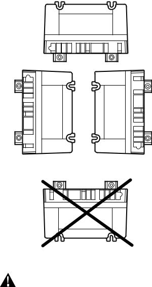
MOUNT IN ONE OF THESE POSITIONS
TERMINALS FACING DOWN
TERMINALS FACING LEFT |
TERMINALS FACING RIGHT |
|
|
DO NOT MOUNT
WITH TERMINALS FACING UP
M2647A
Fig. 1. Module mounting recommendations.
WARNING
EXPLOSION HAZARD. CAN CAUSE
INJURY OR EQUIPMENT DAMAGE.
Only trained professional gas appliance service technicians should install and check out the S8910U.
Selectable DIP switches allow the ignition module to be customized for the appropriate trial count, trial for ignition period, and igniter warm-up time. Use only the appropriate DIP switch configuration as given in Table 4 on page 7. Refer to Tables 1, 2, and 3 for appropriate number of ignition trials, warm-up, prepurge and between trial prepurge timings.
Improper DIP switch configuration can result in appliance malfunction.
S8910U3000
Wire the Module
 CAUTION
1.Check the wiring diagram furnished by the appliance manufacturer, if available, and compare with Table 5. Carefully follow any special instructions affecting the general procedures outlined in this section.
2.Disconnect the power supply before making wiring connections to prevent electrical shock or equipment damage.
IMPORTANT
1.Be sure all wiring complies with applicable electrical codes and ordinances.
2.Hot surface igniter leadwires should not be allowed to rest against grounded metal surfaces.
3.A common ground is required for the S8910U and the main burner. The 24V (GND) terminal internally grounds one side of the transformer. Any auxiliary controls or limits must not be in the grounded leg. In addition, the appliance should be earth-grounded.
4.Make sure the transformer has adequate VA. The ignition module requires 0.4A at 24 Vac. Add the current draws of all other devices in the control circuit, including the pilot and main valves in the gas control, and multiply by 24 to determine the total VA requirement of these components. Add this total to 9.6 VA (for the ignition module). The result is the minimum transformer VA rating. Use a Class II transformer when replacement is required.
5.Check that L1 (hot) and L2 (neutral) are wired to the proper terminals.
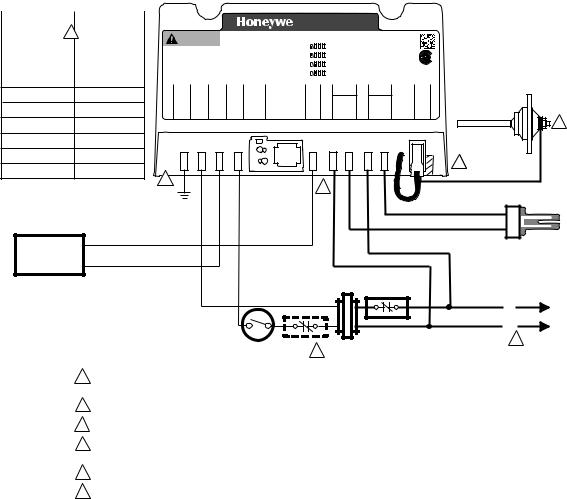
1.Connect the wires to the S8910U Ignition Module as shown in Table 5. Make sure that adequate system ground is provided as indicated in the wiring table. See Fig. 2 through 4. Where a change in quick-connect is required, cut off the original quick-connect, strip the leadwire and firmly crimp in place the proper quick-connect supplied.
2.Verify the thermostat anticipator setting as explained in the preceding IMPORTANT, item 4.
9 |
34-00008EFS—01 |
S8910U3000
Table 5. Replacement Wiring Terminals.
|
|
|
|
|
|
Replacement Control |
|
Original Control |
|
|
|
|
|
|
|
S8910U |
Honeywell |
White Rodgers |
Robertshaw |
Terminal Function |
Terminal |
S89/S890 Terminal |
50E/F47 Terminal |
HS780 Terminal |
|
|
|
|
|
|
|
|
|
|
Burner Ground Connection |
GND (BURNER) |
GND (BURNER)a |
GND |
TR (GND CLIP)b |
Tranformer Secondary |
24V (GND) |
24V (GND)a |
TR |
GND |
(unswitched leg) |
|
|
|
|
|
|
|
|
|
Main Valve Common |
VALVE (GND) |
VALVE (GND)a |
MVa (next to TR |
—c |
|
|
|
terminal) |
|
|
|
|
|
|
Transformer Secondary |
24V |
24Va |
TH |
TH |
(switched leg) |
|
|
|
|
|
|
|
|
|
Main Valve Operator |
VALVE |
VALVE |
MVd |
VALVEd |
120 Vac Neutral Leg Power Supply |
L2 120V NEUTRALe |
L2 120V NEUTRAL |
— |
L2 |
120 Vac Hot Leg Power Supply |
L1 120V HOT |
L1 120V HOT |
Lf |
L1 |
Hot Surface Igniter Element |
HSI 120V NEUTRALe |
HSI 120V |
— |
IGN |
Hot Surface Igniter Element |
HSI 120V HOT |
HSI 120V |
IGNg |
IGN |
Flame Sensor |
SENSEh |
SENh |
FP i |
RSh |
aRemove quick-connect and replace with the included 1/4 in. quick-connect.
bUse green adapter cable (provided) to connect S8910U GND (BURNER) terminal to chassis ground.
cDo not use the S8910U VALVE (GND) terminal. VALVE (GND) and 24V (GND) are interconnected in the appliance wiring.
dRemove quick-connect and replace with the included 3/16 in. quick-connect.
eDo not use this terminal if model being replaced does not have 120V neutral power supply connection.
fUse the black wire on the included adapter cable.
gUse the orange wire on the included adapter cable.
hOn remote sense models, remove jumper quick-connect from S8910U sense terminal, cut jumper wire at circuit board and discard. On local sense models, leave black jumper connected.
iRemove jumper from S8910U sense terminal, cut jumper wire at circuit board and discard.
34-00008EFS—01 |
10 |
S8910U3000
S8910U HOT SURFACE IGNITER CONTROL
|
TERMINAL CROSS |
|
|
|
|
|
|
|
|
|
|
|
|
|
|
|
|
|
|
|
|
|
|
|
|
|
|
|
|
|
|
Golden Valley, MN 55422 |
|
|
|
|
|
|
|
|
|
|
|
|
|
|
|
|
|
|
|
|
|
|
|
|
|
|
|
|||||||||
|
|
|
|
|
|
|
|
|
|
|
|
|
|
|
|
|
|
|
|
|
|
|
|
|
|
|
|
|
|
|
Assembled in Mexico |
|
|
|
|
|
|
|
|
|
|
|
|
|
|
|
|
|
|
|
|
|
|
|
|
|
|
|
||||||||||
|
|
|
|
|
|
|
|
|
|
|
|
|
|
|
|
|
|
|
|
|
|
|
|
|
|
|
|
|
|
|
|
|
|
|
|
|
|
|
|
|
|
|
|
|
|
|
|
|
|
|
|
|
|
|
|
|
|
|
|
|
|
|
|
|
|
|||
|
REFERENCE |
|
|
|
|
|
WARNING |
|
S8910U Hot Surface Ignition |
|
Selection Tab |
|
|
|
|
|
LED States |
|
|
|
|
|
|
|
|
|
|
|
|
|
|
|
|
|
|
|
|
|
|
|||||||||||||||||||||||||||||
|
|
|
|
|
|
|
|
|
|
Input Voltages = 120 & 24 VAC, 60 Hz |
|
|
|
|
|
|
|
|
|
|
|
|
|
|
|
|
|
|
|
|
|
|
|
|
|
|
|
|
||||||||||||||||||||||||||||||
S8910U |
50E/F47 |
|
|
|
|
|
|
|
|
|
|
|
|
|
|
HSI = 120V, 5A max. |
|
|
|
|
|
|
|
ON |
|
|
|
Trial count |
Control Status |
Color |
Pattern |
|
|
|
|
|
|
|
|
|
|
|
|
|
|
|
|
|
|
|||||||||||||||||||
|
|
|
Explosion Hazard. Can cause |
|
Valve = 24V, 2A max. |
|
|
|
|
|
|
OFF |
|
|
|
= 1 try (default) |
Device damaged- |
Red |
|
Steady |
|
|
|
|
|
|
|
|
|
|
|
|
|
|
|
|
|
|
||||||||||||||||||||||||||||||
|
|
|
|
|
|
|
|
|
|
|
|
|
|
|
|
|
|
|
|
|
|
|
|
|
|
|
|
|
|
|
||||||||||||||||||||||||||||||||||||||
|
|
|
|
|
|
|
Total 24V Load = 0.4 + valve load |
|
ON |
|
|
|
Trial count |
replace control |
|
|
|
|
|
|
|
|
|
|
|
|
|
|
|
|
|
|
|
|
|
|
||||||||||||||||||||||||||||||||
GND(BURNER) |
GND |
|
|
|
serious injury or death. |
|
U.S. Patent 8,085,521 |
|
|
|
|
|
|
OFF |
|
|
|
= 3 tries |
Ignition lockout |
Red |
|
Blink |
|
|
® |
|
|
|
|
|
|
|
|
|
|
|
|
|
|
|
||||||||||||||||||||||||||||
|
|
|
Disconnect power before ser- |
|
|
|
|
|
|
|
|
|
|
|
|
|
|
|
|
|
|
|
|
|
|
|
|
|
|
|
||||||||||||||||||||||||||||||||||||||
|
|
|
|
|
|
|
|
|
|
|
|
|
|
|
|
|
|
|
ON |
|
|
|
Trial for ign. period |
|
|
|
|
|
|
|
|
|
|
|
|
|
|
|
|
|
|
|
|
|
||||||||||||||||||||||||
|
|
|
|
Prepurge Time = 32 Sec. |
|
|
|
|
|
|
|
|
|
|
Normal operation |
Green |
Steady |
C |
US |
|
|
|
|
|
|
|
|
|
|
|
|
|
||||||||||||||||||||||||||||||||||||
|
|
|
|
|
|
vicing. This device can mal- |
|
Igniter Warm Up Time = See Inst. Sh. 34-00008 |
OFF |
|
|
|
= 4 seconds (default) |
Weak flame signal |
Green |
Blink |
AUTO |
|
|
|
|
|
|
|
|
|
|
|
|
|
|
|
|
|||||||||||||||||||||||||||||||||||
|
|
|
|
|
|
function if it gets wet. Never |
|
|
ON |
|
|
|
Trial for ign. period |
|
|
|
|
|
|
|
|
|
|
|
|
|
|
|
|
|||||||||||||||||||||||||||||||||||||||
|
|
|
|
|
|
|
Ignition Trial Time - See Selection Tab |
|
|
|
|
See Instruction Sheet 34- |
00008 |
SYSTEMS |
|
|
|
|
|
|
|
|
|
|
|
|
|
|||||||||||||||||||||||||||||||||||||||||
24V (GND) |
TR |
|
|
|
|
|
|
|
|
|
|
|
|
|
|
|
|
|
|
|
|
|
|
|
|
|
|
|
|
|
|
|
|
|
|
|
|
|
|
|
|
|
|
|
|
|
|
|
|
IGNITION |
|
|
|
|
|
|
|
|
|
|
|
|
|
|||||
|
|
|
try to use a device that has |
|
Number of Trials - See Selection Tab |
OFF |
|
|
|
= 7 seconds |
for additional states |
|
|
|
ANSI Z21.20 |
|
|
|
|
|
|
|
|
|
|
|
|
|
||||||||||||||||||||||||||||||||||||||||
|
|
|
|
1 2 3 4 |
|
|
|
|
|
|
|
|
|
|
|
|
|
|
|
|
||||||||||||||||||||||||||||||||||||||||||||||||
|
|
|
been wet -- replace it. |
|
Between Trial Time - 96 Sec. |
|
|
|
|
|
|
|
|
|
|
|
|
|
|
|
32304204-001 Rev. A |
|
|
|
FLAME |
|||||||||||||||||||||||||||||||||||||||||||
|
|
|
|
|
|
|
|
|
|
|
|
|
|
|
|
|
|
|
|
|
|
|
|
|
|
|
||||||||||||||||||||||||||||||||||||||||||
|
|
|
|
|
|
|
BURNER (GND) |
24V (GND) |
VALVE |
(GND) |
|
|
W-TH |
|
LED |
SYSTEM SETUP |
|
VALVE |
|
|
L2 HSI |
|
|
L1 HSI |
|
|
|
|
SENSE |
|
|
|
|
|
|
|||||||||||||||||||||||||||||||||
VALVE (GND) |
MV (NEXT TO TR) |
|
|
|
|
|
|
|
|
|
|
|
|
|
|
|
|
|
|
|
See |
NOTE: ALWAYS apply |
|
|
|
|
|
|
|
120 VAC |
|
|
120 VAC |
|
See |
|
|
|
|
|
|
|
|
|
|
|
|
|
|
|
|
|
|
|||||||||||||||
|
|
|
|
|
|
|
|
|
|
|
|
|
|
|
|
|
|
|
LED |
this control as instructed |
|
|
|
|
|
NEUTRAL |
|
|
HOT |
|
|
|
|
|
|
|
|
|
|
|
|
|
|
|
|
|
|
|
||||||||||||||||||||
|
|
|
|
|
|
|
|
|
|
|
|
|
|
|
|
|
|
|
|
|
States |
in Instruction Sheet |
|
|
|
|
|
|
|
|
|
|
|
|
|
|
|
|
Instructions |
|
|
|
|
|
|
|
|
|
|
|
|
|
|
|
|
|
|
|||||||||||
24V |
|
TH |
|
|
|
|
|
|
|
|
|
|
|
|
|
|
|
|
|
|
|
|
|
|
34-00008 |
|
|
|
|
|
|
|
|
|
|
|
|
|
|
|
|
|
|
|
for |
|
|
|
|
|
|
|
|
|
|
|
|
|
|
|
|
|
|
|||||
|
|
|
|
|
|
|
|
|
|
|
|
|
|
|
|
|
|
|
|
|
|
|
|
|
|
|
|
|
|
|
|
|
|
|
|
|
|
|
|
|
Single/Dual |
|
|
|
|
|
|
|
|
|
|
|
|
|
|
|
|
|
|
|||||||||
|
|
|
|
|
|
|
|
|
|
|
|
|
|
|
|
|
|
|
|
|
|
|
|
|
|
|
|
|
|
|
|
|
|
|
|
|
|
|
|
|
|
|
|
|
|
Rod |
|
|
|
|
|
|
|
|
|
|
|
|
|
|
|
|
|
|
||||
VALVE |
|
MV |
|
|
|
|
|
|
|
|
|
|
|
|
|
|
|
|
|
|
|
|
|
|
|
|
|
|
|
|
|
|
|
|
|
|
|
|
|
|
|
|
|
|
|
|
Applications |
|
|
|
|
|
|
|
|
SENSOR |
|
|
|
|
|
|
|
|||||
L2 |
|
— |
|
|
|
|
|
|
|
|
|
|
|
|
|
|
|
|
|
|
|
|
|
|
|
|
|
|
|
|
|
|
|
|
|
|
|
|
|
|
|
|
|
|
|
|
|
|
|
|
|
|
|
|
|
|
|
|
|
|
|
|
|
|
|
|
|
|
|
|
|
|
|
|
|
|
|
|
|
|
|
|
|
|
|
|
|
|
|
|
|
|
|
|
|
|
|
|
|
|
|
|
|
|
|
|
|
|
|
|
|
|
|
|
|
|
|
|
|
|
|
|
|
|
|
|
|
|
|
|
|
|
|
|
|||
|
|
|
|
|
|
|
|
|
|
|
|
|
|
|
|
|
|
|
|
|
|
|
|
|
|
|
|
|
|
|
|
|
|
|
|
|
|
|
|
|
|
|
|
|
|
|
|
|
|
|
|
|
|
|
|
|
|
|
|
|
|
|
|
|
|
|
|
|
L1 |
4 |
L |
|
|
|
|
|
|
|
|
|
|
|
|
|
|
|
|
|
|
|
|
|
|
|
|
|
|
|
|
|
|
|
|
|
|
|
|
|
|
|
|
|
|
|
|
|
|
|
|
|
|
|
|
|
|
|
|
|
|
|
|
|
|
|
|
|
|
|
|
|
|
|
|
|
|
|
|
|
|
|
|
|
|
|
|
|
|
|
|
|
|
|
|
|
|
|
|
|
|
|
|
|
|
|
|
|
|
|
|
|
|
|
|
|
|
|
|
|
|
|
|
|
|
|
|
|
|
|
|
|
|
|
|
|||
HSI |
|
— |
|
|
|
|
|
|
|
|
|
|
|
|
|
|
|
|
|
|
|
|
|
|
|
|
|
|
|
|
|
|
|
|
|
|
|
|
|
|
|
|
|
|
|
|
|
|
|
|
|
|
|
|
|
3 |
|
|
|
|
|
|
|
|
|
|
|
|
|
|
|
|
|
|
|
|
|
|
|
|
|
|
|
|
|
|
|
|
|
|
|
|
|
|
|
|
|
|
|
|
|
|
|
|
|
|
|
|
|
|
|
|
|
|
|
|
|
|
|
|
|
|
|
|
|
|
|
|
|
|
|
|
|
|
|
||
HSI |
4 |
IGN |
|
|
|
|
|
|
|
|
|
|
|
|
|
|
|
|
|
|
|
|
|
|
|
|
|
|
|
|
|
|
|
|
|
|
|
|
|
|
|
|
|
|
|
|
|
|
|
|
|
|
|
|
|
|
|
|
|
|
|
|
|
|
|
|
|
|
|
|
|
|
|
|
|
|
|
|
|
|
|
|
|
|
|
|
|
|
|
|
|
|
|
|
|
|
|
|
|
|
|
|
|
|
|
|
|
|
|
|
|
|
|
|
|
|
|
|
|
|
|
|
|
|
|
|
|
|
|
|
|
|
|
|
|||
SENSE |
FP |
|
BURNER |
|
|
|
|
|
|
|
|
|
5 |
|
|
|
|
|
|
|
|
|
|
|
|
|
|
6 |
4 |
|
|
|
|
|
|
|
|
|
|
|
|
|
|
|
|
|
|
|
|
|
|
|
|
|
|
|
||||||||||||
|
|
|
|
|
|
|
|
|
|
|
|
|
|
|
|
|
|
|
|
|
|
|
|
|
|
|
|
|
|
|
|
|
|
|
|
|
|
|
|
|
|
|
|
|
|
|
|
|
||||||||||||||||||||
|
|
|
|
GROUND |
|
|
|
|
|
|
|
|
|
|
|
|
|
|
|
|
|
|
|
|
|
|
|
|
|
|
|
|
|
|
|
|
|
|
|
|
|
|
ORANGE |
|
|
|
|
|
|
|
|
|
|
|
|
|
|
|
|
|||||||||
|
|
|
|
|
|
|
|
|
|
|
|
|
|
|
|
|
|
|
|
|
|
|
|
|
|
|
|
|
|
|
|
|
|
|
|
|
|
|
|
|
|
|
|
|
|
|
|
|
|
|
|
|
|
|
|
|
|
|
|
|
|
|
||||||
|
|
|
|
|
|
|
|
|
|
MV |
|
|
|
|
|
|
|
|
|
|
|
|
|
|
|
|
|
|
|
|
|
|
|
|
|
|
|
|
|
|
|
BLACK |
|
|
|
|
|
|
HOT SURFACE |
|||||||||||||||||||
|
|
|
|
COMBINATION |
|
|
|
|
|
|
|
|
|
|
|
|
|
|
|
|
|
|
|
|
|
|
|
|
|
|
|
|
|
|
|
|
|
|
ADAPTER |
|
|
|
4 IGNITER |
|||||||||||||||||||||||||
|
|
|
|
GAS CONTROL MV |
|
|
|
|
|
|
|
|
|
|
|
|
|
|
|
|
|
|
|
|
|
|
|
|
|
|
|
|
|
|
|
|
|
|
|
|
|
|||||||||||||||||||||||||||
|
|
|
|
|
|
|
|
|
|
|
|
|
|
|
|
|
|
|
|
|
|
|
|
|
|
|
|
|
|
|
|
|
|
|
|
|
|
|
|
|
|
|
|
|
|
|
|
|
|
|
||||||||||||||||||
|
|
|
|
|
|
|
|
|
|
|
|
|
|
|
|
|
|
|
|
|
|
|
|
|
|
|
|
|
|
|
|
|
|
|
|
|
|
|
|
|
|
|
|
|
|
|
|
|
|
|
|
|
|
|
|
|
||||||||||||
|
|
|
|
|
|
|
|
|
|
|
|
|
|
|
|
|
|
|
|
|
|
|
|
|
|
|
|
|
|
|
|
|
|
|
|
|
|
|
|
|
|
|
|
|
|
|
|
|
|
|
|
|
|
|
|
|
||||||||||||
|
THERMOSTAT OR |
LIMIT |
|
|
CONTROLLER |
||
|
CONTROLLER |
||
1 |
L1 |
||
POWER SUPPLY. PROVIDE DISCONNECT MEANS AND OVERLOAD |
|||
|
PROTECTION AS REQUIRED. MAKE SURE L1 AND L2 ARE NOT REVERSED. |
(HOT) |
|
2 |
ALTERNATE LIMIT CONTROLLER LOCATION. |
L2 |
|
1 |
|||
|
2 |
3REMOVE JUMPER QUICK-CONNECT FROM S8910U. CUT WIRE AT CIRCUIT BOARD AND DISCARD.
4USE ADAPTER PLUG WITH BLACK AND ORANGE WIRES (SUPPLIED).
5CUT 3/16 IN. QUICK-CONNECT OFF WIRE AND REPLACE WITH 1/4 IN. QUICK-CONNECT (SUPPLIED).
6 CUT 3/16 IN. QUICK-CONNECT OFF WIRE AND REPLACE WITH 3/16 IN. QUICK-CONNECT (SUPPLIED). |
M8528E |
Fig. 2. Typical hookup when S8910U replaces White-Rodgers 50E/F47.
11 |
34-00008EFS—01 |
S8910U3000
TERMINAL CROSS |
|
S8910U HOT SURFACE IGNITER CONTROL |
|
|
|||||||||||
REFERENCE |
|
|
|
|
|
|
|
|
|
|
|
|
|
|
|
S8910U |
HS780 |
|
|
|
|
|
|
|
Golden Valley, MN 55422 |
|
|
|
|
||
|
|
|
|
|
|
|
|
|
|
|
|||||
|
|
|
|
|
|
|
|
|
|
Assembled in Mexico |
|
|
|
|
|
GND(BURNER) 6 |
TR (GND CLIP) |
WARNING |
|
S8910U Hot Surface Ignition |
Selection Tab |
|
LED States |
|
|
||||||
|
|
|
|
||||||||||||
|
|
|
|
|
Input Voltages = 120 & 24 VAC, 60 Hz |
|
|
|
|||||||
24V (GND) |
GND |
|
|
|
|
HSI = 120V, 5A max. |
ON |
|
Trial count |
Control Status |
Color |
Pattern |
|
||
Explosion Hazard. Can cause |
|
|
Valve = 24V, 2A max. |
OFF |
|
= 1 try (default) |
Device damaged- |
Red |
Steady |
|
|||||
|
|
|
|
||||||||||||
|
|
Total 24V Load = 0.4 + valve load |
ON |
|
Trial count |
replace control |
|
|
|
||||||
|
|
|
serious injury or death. |
|
|
U.S. Patent 8,085,521 |
|
OFF |
|
= 3 tries |
Ignition lockout |
Red |
Blink |
® |
|
|
|
|
Disconnect power before ser- |
|
|
|
|||||||||
VALVE (GND) |
— |
|
Prepurge Time = 32 Sec. |
ON |
|
Trial for ign. period |
Normal operation |
Green |
Steady |
C US |
|||||
vicing. This device can mal- |
|
Igniter Warm Up Time = See Inst. Sh. 34-00008 |
OFF |
|
= 4 seconds (default) |
Weak flame signal |
Green |
Blink |
AUTO |
||||||
|
|
|
function if it gets wet. Never |
|
Ignition Trial Time - See Selection Tab |
ON |
|
Trial for ign. period |
See Instruction Sheet 34- |
00008 |
SYSTEMS |
||||
|
|
|
|
|
|
|
|
|
|
|
|
|
|
|
IGNITION |
24V |
TH |
try to use a device that has |
|
Number of Trials - See Selection Tab |
OFF |
|
= 7 seconds |
for additional states |
|
ANSI Z21.20 |
|||||
|
1 2 3 4 |
|
|||||||||||||
been wet -- replace it. |
|
Between Trial Time - 96 Sec. |
|
|
|
|
32304204-001 Rev. A |
||||||||
|
|
|
|
|
|
||||||||||
L2 |
L2 |
BURNER (GND) |
24V |
(GND) |
VALVE (GND) |
W-TH |
LED |
SYSTEM SETUP |
VALVE |
L2 HSI |
L1 HSI |
|
SENSE |
|
|
|
|
|
|
|
|
See |
NOTE: ALWAYS apply |
|
120 VAC |
120 VAC |
See |
|
|
VALVE |
VALVE |
|
|
|
|
|
LED |
this control as instructed |
|
NEUTRAL |
HOT |
Instructions |
|
|
|
|
|
|
|
States |
in Instruction Sheet |
|
|
|
for |
|
FLAME |
||
|
|
|
|
|
|
|
|
34-00008 |
|
|
|
Single/Dual |
|
|
|
|
|
|
|
|
|
|
|
|
|
|
Rod |
|
SENSOR |
|
|
|
|
|
|
|
|
|
|
|
|
Applications |
|
|
L1 |
L1 |
|
|
|
|
|
|
|
|
|
|
|
|
3 |
HSI |
IGN |
|
|
|
|
|
|
|
|
|
|
|
|
|
HSI |
IGN |
|
|
|
|
|
|
|
|
|
|
|
|
4 |
SENSE |
RS |
|
|
|
|
|
|
|
|
|
|
|
|
|
6 |
|
|
|
|
|
|
|
|
|
|
|
|
||
|
|
|
|
|
|
|
|
|
5 |
|
|
|
|
|
|
|
BURNER |
|
|
|
|
|
|
|
|
|
|
|
|
|
|
|
|
|
|
|
|
|
|
|
|
|
|
|
|
|
GROUND |
|
|
|
|
|
|
|
|
|
|
|
|
|
MV |
|
|
|
|
|
|
|
|
|
|
|
|
HOT |
COMBINATION |
|
|
|
|
|
|
|
|
|
|
|
|
|
|
|
|
|
|
|
|
|
|
|
|
|
|
|
SURFACE |
|
GAS CONTROL |
MV |
|
|
|
|
|
|
|
|
|
|
|
|
|
|
|
|
|
|
|
|
|
|
|
|
|
IGNITER |
||
|
|
|
|
|
|
|
|
|
|
|
|
|
|
|
|
|
|
|
|
|
|
|
|
|
|
LIMIT |
|
|
|
|
|
|
|
|
|
|
|
|
|
|
CONTROLLER |
|
|
|
|
|
|
|
|
|
|
|
|
|
|
|
|
|
L1 |
|
|
|
|
|
|
|
|
|
|
|
|
|
|
(HOT) |
|
|
|
|
|
|
|
|
|
|
|
|
|
|
L2 |
|
|
|
|
|
|
THERMOSTAT OR |
|
|
|
|
|
1 |
||
|
|
|
|
|
|
2 |
|
|
|
|
|
|||
|
|
|
|
|
|
CONTROLLER |
|
|
|
|
|
|||
|
|
|
|
|
|
|
|
|
|
|
|
|||
1POWER SUPPLY. PROVIDE DISCONNECT MEANS AND OVERLOAD PROTECTION AS REQUIRED. MAKE SURE L1 AND L2 ARE NOT REVERSED.
2ALTERNATE LIMIT CONTROLLER LOCATION.
3SENSE ROD WILL BE PRESENT IF REMOTE SENSE HS780 MODEL. SEE TABLE 2.
4WHEN HS780 IS A REMOTE SENSE MODEL, REMOVE JUMPER QUICK-CONNECT FROM S8910U. CUT WIRE AT CIRCUIT BOARD AND DISCARD. CONNECT FLAME ROD LEAD WIRE TO SENSE. SEE TABLE 2.
5CUT 1/4 IN. QUICK-CONNECT OFF WIRE AND REPLACE WITH 3/16 IN. QUICK-CONNECT (SUPPLIED).
6 USE GREEN GROUND ADAPTER (SUPPLIED) TO CONNECT S8910U GND (BURNER) TO APPLIANCE CHASSIS. |
M8529E |
Fig. 3. Typical hookup when S8910U replaces Robertshaw HS780.
34-00008EFS—01 |
12 |
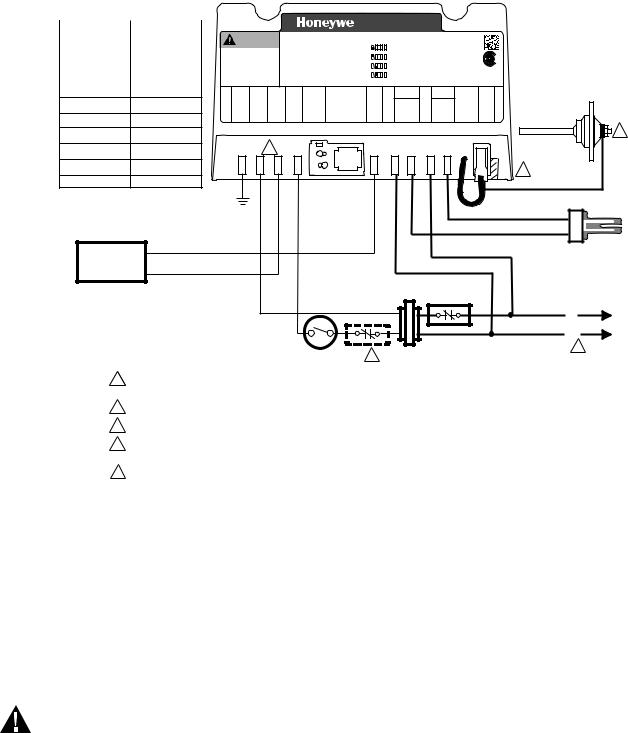
S8910U3000
S8910U HOT SURFACE IGNITER CONTROL
TERMINAL CROSS
REFERENCE
|
|
|
|
|
|
|
Golden Valley, MN 55422 |
|
|
|
|
|
|
S8910U |
S89/S890 |
|
|
|
|
|
Assembled in Mexico |
|
|
|
|
|
|
WARNING |
S8910U Hot Surface Ignition |
Selection Tab |
LED States |
|
|
|
|
||||||
GND(BURNER) |
GND (BURNER) |
|
|
|
|
||||||||
Input Voltages = 120 & 24 VAC, 60 Hz |
ON |
|
Trial count |
Control Status |
Color |
Pattern |
|
|
|||||
|
HSI = 120V, 5A max. |
|
|
|
|||||||||
|
|
Explosion Hazard. Can cause |
Valve = 24V, 2A max. |
OFF |
|
= 1 try (default) |
Device damaged- |
Red |
Steady |
|
|
||
|
|
|
|
|
|||||||||
24V (GND) |
24V (GND) |
Total 24V Load = 0.4 + valve load |
ON |
|
Trial count |
replace control |
|
|
|
|
|||
serious injury or death. |
U.S. Patent 8,085,521 |
OFF |
|
= 3 tries |
Ignition lockout |
Red |
Blink |
|
® |
||||
|
|
Disconnect power before ser- |
Prepurge Time = 32 Sec. |
|
ON |
|
Trial for ign. period |
Normal operation |
Green |
Steady |
C |
US |
|
|
|
vicing. This device can mal- |
Igniter Warm Up Time = See Inst. Sh. 34-00008 |
OFF |
|
= 4 seconds (default) |
Weak flame signal |
Green |
Blink |
AUTO |
|
||
VALVE (GND) |
VALVE (GND) |
function if it gets wet. Never |
Number of Trials - See Selection Tab |
ON |
|
Trial for ign. period |
for additional states |
|
IGNITION |
||||
try to use a device that has |
OFF |
|
= 7 seconds |
|
ANSI Z21.20 |
||||||||
|
|
|
Ignition Trial Time - See Selection Tab |
|
|
|
See Instruction Sheet 34-00008 |
SYSTEMS |
|||||
|
|
been wet -- replace it. |
Between Trial Time - 96 Sec. |
|
1 2 3 4 |
|
|
|
|
|
|
||
|
|
|
|
|
|
32304204-001 Rev. A |
|||||||
|
|
|
|
|
|
||||||||
24V |
24V |
|
BURNER (GND) |
24V |
(GND) |
VALVE (GND) |
-THW |
See |
NOTE: ALWAYS apply |
VALVE |
120 VAC |
120 VAC |
See |
SENSE |
FLAME |
|
|
|
LED |
SYSTEM SETUP |
L2 HSI |
L1 HSI |
Rod |
||||||||
|
|
|
|
|
|
|
|
LED |
this control as instructed |
|
NEUTRAL |
HOT |
Instructions |
|
|
VALVE |
VALVE |
|
|
|
|
|
States |
in Instruction Sheet |
|
|
|
for |
|
|
|
|
|
|
|
|
|
34-00008 |
|
|
|
Single/Dual |
|
|
|||
L2 |
L2 |
|
|
|
|
|
|
|
|
|
|
|
Applications |
|
SENSOR |
|
|
|
|
|
|
|
|
|
|
|
|
|
|||
L1 |
L1 |
|
|
|
|
|
|
|
|
|
|
|
|
|
3 |
|
|
|
|
|
|
|
|
|
|
|
|
|
|
||
HSI |
HSI |
|
|
|
|
5 |
|
|
|
|
|
|
|
|
|
|
|
|
|
|
|
|
|
|
|
|
|
|
|
||
HSI |
HSI |
|
|
|
|
|
|
|
|
|
|
|
|
|
4 |
|
|
|
|
|
|
|
|
|
|
|
|
|
|
|
|
SENSE |
SEN |
|
|
|
|
|
|
|
|
|
|
|
|
|
|
|
|
|
BURNER |
|
|
|
|
|
|
|
|
|
|
|
|
|
|
|
GROUND |
|
|
|
|
|
|
|
|
|
|
|
|
COMBINATION |
MV |
|
|
|
|
|
|
|
|
|
|
|
|
HOT |
|
|
|
|
|
|
|
|
|
|
|
|
|
|
SURFACE |
||
GAS CONTROL |
MV |
|
|
|
|
|
|
|
|
|
|
|
|
IGNITER |
|
|
|
|
|
|
|
|
|
|
|
|
|
LIMIT |
|
|
|
|
|
|
|
|
|
|
|
|
|
|
|
CONTROLLER |
|
|
|
|
|
|
|
|
|
|
|
|
|
|
|
|
|
|
L1 |
|
|
|
|
|
|
|
|
|
|
|
|
|
|
|
(HOT) |
|
|
|
|
|
|
|
|
|
|
|
|
|
|
|
L2 |
|
|
|
|
|
|
|
THERMOSTAT OR |
2 |
|
|
|
|
1 |
||
|
|
|
|
|
|
|
|
|
|
|
|
||||
|
|
|
|
|
|
|
CONTROLLER |
|
|
|
|
|
|
||
1POWER SUPPLY. PROVIDE DISCONNECT MEANS AND OVERLOAD PROTECTION AS REQUIRED. MAKE SURE L1 AND L2 ARE NOT REVERSED.
2ALTERNATE LIMIT CONTROLLER LOCATION.
3SENSE ROD WILL BE PRESENT IF REMOTE SENSE S89/S890 MODEL. SEE TABLE 3.
4WHEN S89/S890 IS A REMOTE SENSE MODEL, REMOVE JUMPER QUICK-CONNECT FROM S8910U. CUT WIRE AT CIRCUIT BOARD AND DISCARD. CONNECT FLAME ROD LEAD WIRE TO SENSE. SEE TABLE 3.
5 |
CUT QUICK-CONNECTS OFF WIRES AND REPLACE WITH 1/4 IN. QUICK-CONNECTS (PROVIDED). |
M8530E |
Fig. 4. Typical hookup when S8910U replaces Honeywell S89/S890.
STARTUP AND CHECKOUT
Check out the gas control system:
•At initial installation of the appliance.
•As part of regular maintenance procedures.
•At maintenance intervals determined by the application.
•As the first step in troubleshooting.
•Any time work is done on the system.
Determine maintenance frequency individually for each application; see Maintenance section.
WARNING
FIRE OR EXPLOSION HAZARD.
CAN CAUSE PROPERTY DAMAGE, SEVERE INJURY, OR DEATH.
1.If you smell gas or suspect a gas leak, turn off gas at the manual service valve and evacuate the building. Do not try to light any appliance; do not touch any electrical switch or telephone in the building until you are sure no spilled gas remains.
2.Perform a gas leak test, as described in Steps 1 and 6 in the Startup and Checkout section, for initial installation and any time work is done involving the gas piping.
Step 1: Perform visual inspection.
a.With power off, make sure all wiring connections are clean and tight.
b.Turn on the power to the appliance and the S8910U.
c.Open the manual shutoff valves in the gas line to the appliance.
d.Test for a gas leak upstream of the gas control if the piping has been disturbed.
GAS LEAK TEST: Paint gas control gasket edges and all pipe connections upstream of the gas control with a rich soap and water solution. Bubbles indicate gas leaks. Tighten the joints and screws or replace the component to stop a gas leak. Recheck with soap and water solution.
13 |
34-00008EFS—01 |
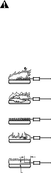
S8910U3000
Step 2: Verify control system ground.
The ignition module must share a common ground with the main burner. The burner serves as the common grounding area to assure reliable flame detection. If there is not good metal-to-metal contact between the burner and ground, run a lead from the burner to ground.
Step 3: Review normal operating sequence and module specifications. See Operation and Application sections.
Step 4: Reset the ignition module.
a.Turn the thermostat or controller to the lowest setting.
b.Turn on the system power.
c.Wait one minute.
As you do Steps 5 and 6, watch for points where operation deviates from normal. Refer to Troubleshooting section to correct the problem.
Step 5: Check the safety lockout operation.
a.Turn off the gas supply.
b.Set the thermostat or controller above the room temperature to call for heat.
c.Watch for igniter warmup following prepurge. Igniter starts to glow several seconds after it is powered.
d.Time the length of time gas control is energized; measure the time by connecting a voltmeter across the gas valve terminals.
e.When configuring control for three ignition trials, watch for the start of the 96-second between trial purge, followed by a configured igniter warmup period and a second try for ignition. After a third purge, warmup, and trial for ignition sequence, the S8910U should lock out. The LED displays a brief red flash. Refer to Table 6 for a complete list of LED codes.
f.Open the manual gas control knob and make sure no gas is flowing to the burner.
g.Set the thermostat below the room temperature and wait one minute before continuing.
Step 6: Check normal operation.
a.Set the thermostat or the controller above the room temperature to call for heat.
b.Observe the lightoff sequence and make sure the main burner lights smoothly without flashback.
c.Make sure the burner operates smoothly without floating, lifting, or flame rollout to the furnace vestibule or heat buildup in the vestibule.
d.Test for a gas leak downstream of the gas control if the piping has been disturbed.
GAS LEAK TEST: Paint the gas control gasket edges and all pipe connections downstream of the gas control with a rich soap and water solution. Bubbles indicate a gas leak. Tighten the joints and screws or replace the component to stop a gas leak. Recheck with soap and water solution.
e.Check the burner flame condition. The igniter-sensor or sensor must be constantly immersed in flame. Check the burner flame condition as shown in Fig. 5. Do not relocate the hot surface igniter or flame rod.
f.Turn the thermostat or controller below the room temperature. Make sure the main burner and the pilot flames go out.
WARNING
FIRE OR EXPLOSION HAZARD.
CAN CAUSE PROPERTY DAMAGE, SEVERE INJURY, OR DEATH.
Improper location of the 120 Vac hot surface igniter or any flame sensing rod can result in appliance malfunction.
1.Never attempt to relocate the 120 Vac hot surface igniter or the flame sensing rod from the original position established by the appliance manufacturer.
2.Be sure the 120 Vac hot surface igniter or the flame sensing rod is replaced in exactly the original position after removal for inspection, service or replacement.
CHECK BURNER FLAME CONDITION
NOISY |
|
LIFTING |
|
FLAME |
CHECK FOR: |
|
|
|
• HIGH GAS PRESSURE |
|
• EXCESS PRIMARY AIR |
|
OR DRAFT |
BURNER |
|
WAVING |
CHECK FOR: |
FLAME |
|
|
• POOR DRAFT |
|
• EXCESS DRAFT |
|
• HIGH VELOCITY OR |
|
SECONDARY AIR |
SMALL |
INSTALL SHIELD IF NECESSARY |
|
|
BLUE |
|
FLAME |
CHECK FOR: |
|
|
|
• CLOGGED PORTS OR |
|
ORIFICE FILTER |
|
• WRONG SIZE ORIFICE |
LAZY |
|
YELLOW |
|
FLAME |
CHECK FOR LACK OF |
|
AIR FROM: |
|
• DIRTY PRIMARY |
|
AIR OPENING |
|
• LARGE PORTS |
GOOD |
OR ORIFICES |
|
|
RECTIFYING |
|
FLAME
3/4 TO 1 IN. (19 TO 25 MM) |
|
1/4 TO 1/2 IN. (6 TO 13 MM) |
M8446B |
Fig. 5. Check burner flame condition.
OPERATION
The S8910U is a direct ignition control used with 120 Vac timed warmup hot surface igniter. The control provides operating control and shuts off all gas flow on ignition failure or loss of main burner flame in central heat furnaces and other heating appliances.
Module operation is in three phases—prepurge/igniter warmup, trial for ignition and burner operation. The S8910U provides one or three trials for ignition, depending on the DIP switch configuration. Fig. 6 shows the normal operating sequence.
34-00008EFS—01 |
14 |
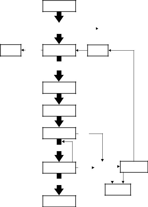
Purge/Prepurge
When the S8910U is used in a fan-assisted combustion system, the combustion air blower starts on a call for heat from the thermostat. On proof of airflow, the air proving switch closes and energizes the S8910U. When the S8910U is used in an atmospheric system, the call for heat energizes the module.
S8910U3000
In either case, the S8910U first initiates a 32-second delay to allow system prepurge.
Igniter Warmup
After prepurge, the S8910U energizes the igniter to start the igniter warmup. The module energizes the hot surface igniter for the selected warmup period; the gas control is closed during this period.
CALL FOR HEAT (24V
TERMINAL POWERED)
|
|
|
|
|
|
|
|
WELDED |
|
DEVICE LOCKED |
|
INITIALIZATION CHECKS |
|
RELAYS |
|
|
|
|
|
|
(REPLACE CONTROL) |
||
|
|
DETECTED |
|
|
|
|
|
|
|
||
|
|
|
|
|
|
SYSTEM WILL
FLAME
NOT START
SIMULATING
FAILURE
PREPURGE (32 SEC)
NO FLAME
SIMULATING
FAILURE
IGNITER WARMS UP (7 (12), 17 (27), 34 OR 45 SEC)
GAS CONTROL OPENS
FOR TIMED TRIAL
FOR IGNITION.
IGNITER OFF;
FLAME SENSING BEGINS.
FLAME
PRESENT
GAS CONTROL STAYS
OPEN (MAIN BURNER
RUNS).
CALL FOR HEAT
IS SATISFIED.
GAS CONTROL CLOSES (MAIN BURNER OFF).
INTERPURGE (64 SEC)
NO
FLAME
|
|
|
|
THREE |
||
|
|
|
GAS |
TRIALS |
||
FLAME |
|
|
|
|
|
|
|
|
CONTROL |
|
|
|
|
FAILURE |
|
|
|
|
|
|
|
|
CLOSES |
|
|
|
|
|
|
|
|
|
|
|
|
|
|
ONE |
|
|
|
|
|
|
TRIAL |
|
|
|
|
|
|
|
|
|
|
LESS
THAN
THREE
HOW MANY IGNITION TRIALS COMPLETED THIS CALL FOR HEAT?
THREE
LOCKOUT OCCURS.
SYSTEM MUST BE
RESET.
M35558
Fig. 6. S8910U normal operating sequence.
15 |
34-00008EFS—01 |

S8910U3000
Trial for Ignition
At the end of the warmup period, the gas control opens for the ignition trial time determined by the DIP switch configuration. The hot surface igniter stays powered for an ignition activation period of two seconds if the four second trial time is used or five seconds if the seven second trial time is used. The igniter turns off after the ignition activation period. Near the end of the ignition trial time, the flame rectification sensing circuit determines if the main burner flame is present. If so, the gas control remains open and the burner operation phase begins.
Burner Operation
When the main burner is lit, a flame rectification circuit is completed between the flame sensor (igniter on local sense systems or flame rod on remote sense systems) and the main burner (burner ground). The S8910U flame sensing circuit detects the flame current and holds open the gas control. The main flame is monitored continuously during the call for heat.
Safety Shutdown
One Trial
If flame is not sensed by the end of the timed trial for ignition, the gas control closes and the module locks out. It must be manually reset by removing power or setting the thermostat below the room temperature for at least 30 seconds.
If the burner lights and flame is proved but goes out during the run cycle, the gas control closes and the module locks out. It must be manually reset by removing power or setting the thermostat below the room temperature for at least 30 seconds.
Three Trial
If flame is not sensed by the end of the first timed trial for ignition, the gas control closes and the module initiates a second 96 seconds between trial purge cycle, followed by igniter warmup and a second trial for ignition. If flame is not established, the between trial purge, warmup, trial for ignition cycle is repeated a third time. If flame is still not established following the third trial, the gas control closes and the module locks out. It must be manually reset by removing power or setting the thermostat below the room temperature for at least 30 seconds.
If the burner goes out during the run cycle, the gas control closes and the module checks for the number of ignition trials performed during the current call for heat. If the number is less than three, the module initiates a between trial purge, warmup and trial for ignition. After the third trial during a single call for heat, the module locks out. The module must be manually reset following the lockout.
MAINTENANCE
WARNING
FIRE OR EXPLOSION HAZARD.
CAN CAUSE PROPERTY DAMAGE, SEVERE INJURY, OR DEATH.
Do not attempt to take apart the module or to clean it. Improper assembly and cleaning can cause unreliable operation.
Regular preventive maintenance is important in applications that place a heavy load on system controls such as those used in the commercial cooking and agricultural and industrial industries because:
•In many such applications, particularly commercial cooking, the equipment operates 100,000 to 200,000 cycles per year. This heavy cycling can wear out the gas control in one to two years.
•Exposure to water, dirt, chemicals and heat can damage the gas control and shut down the control system. A NEMA 4 enclosure can reduce exposure to environmental contaminants.
The maintenance program should include regular checkout of the system as outlined in the Startup and Checkout section, and checkout of the control system as described in the appliance manufacturer literature.
Maintenance frequency must be determined individually for each application. Some considerations are:
•Cycling frequency. Appliances that may cycle 20,000 times annually should be checked monthly.
•Intermittent use. Appliances that are used seasonally should be checked before shutdown and again before the next use.
•Consequence of unexpected shutdown. Where the cost of an unexpected shutdown would be high, the system should be checked more often.
•Dusty, wet, or corrosive environment. Because these environments can cause the gas control to deteriorate more rapidly, the system should be checked more often.
Any control should be replaced if it does not perform properly on checkout or troubleshooting. In addition, replace any module if it is wet or looks like it has ever been wet. Protective enclosures, as described in the Planning the Installation section, are recommended regardless of checkout frequency.
TROUBLESHOOTING
IMPORTANT
1.The following service procedures are provided as a general guide. Follow the appliance manufacturer service instructions if available.
2.Meter readings between gas control and ignition module must be taken within the trial for ignition period. Once the ignition module shuts off, wait for retry or reset at the thermostat.
3.If any component does not function properly, make sure it is correctly installed and wired before replacing it.
34-00008EFS—01 |
16 |
4.The ignition module cannot be repaired. If it malfunctions, replace it.
5.Only trained, experienced service technicians should service hot surface ignition systems.
6.After servicing, verify proper system operation.
Perform the checkout steps in the Startup and Checkout section as the first step in troubleshooting. Then check the troubleshooting sequence (Fig. 7) to determine the exact the cause of the problem.
After troubleshooting, perform the checkout procedure again to be sure the system is operating normally.
Status LED Used to Troubleshoot
The LED can be used to check the appliance status. A description of the LED signals follows. Refer to Table 6 on page 18 for a complete list of LED codes.
IMPORTANT
The LED displays system status for the current call for heat. When the call for heat is interrupted (thermostat satisfied or system power switched off), the LED goes off and the status information is lost.
•A steady green LED indicates the normal operating mode during a call for heat (24 V terminal is powered). The system can be in any of the normal operating modes including prepurge, warmup, ignition trial, between trial purge, or normal run.
•An intermittant red flash, and two, three, or four yellow flashes indicate a lockout mode. Refer to Table 6 for a complete list of LED codes. The most probable cause is the main burner failing to light or failure to detect the flame. Run the appliance through a call for heat and if the burner does not light, check the:
—gas supply
—input voltage
—hot surface igniter
—gas control
—wiring
If the main burner lights, but goes out at the end of ignition trial, check the:
—igniter/sensor
—flame rod
—burner ground connections
—wiring
•Intermittant green flashes indicates the flame rectification signal is weak. The most probable causes are:
—contaminated or mislocated igniter/sensor or flame rod
—poor flame sense leadwire insulation or connections
—poor gas pressure
If the flame rectification signal is strong when the appliance lights, but weak while heat is being delivered, check for overheating of the igniter/sensor, flame rod ceramic or flame sense leadwires.
•Four yellow flashes indicate an internal error. The most probable cause is an S8910U logic failure. Start a new call for heat and if the four-flash signal returns wait 1 to 2 hours and repeat the last step. If the four-flash signal returns again, replace the S8910U.
•A steady red LED indicates a device lockout due to a detected welded gas valve relay. Replace the control.
S8910U3000
Ignition System Checks
Step 1: Check igniter wire harness.
Make sure:
a.Ignition cable does not run in contact with any metal surfaces.
b.Connections to the ignition module and to the igniter or igniter-sensor are clean and tight.
c.Ignition cable provides good electrical continuity.
Step 2: Check ignition system grounding. Nuisance shutdowns are often caused by a poor or erratic ground.
a.A common ground is required for the module, igniter, flame sensor and main burner.
•Check for good metal-to-metal contact between the igniter bracket and the main burner.
•Check the ground path from the GND (BURNER) terminal on the module to the main burner. Make sure connections are clean and tight. If the wire is damaged or deteriorated, replace it by following the appliance manufacturer instructions. A temporary leadwire connection between the GND (BURNER) terminal and the main burner can help confirm a ground path problem.
•Check the temperature at the igniter ceramic or flame sensor insulator. Excessive temperature permits leakage to ground. Contact the appliance manufacturer if the temperature exceeds rating of igniter or sensor.
•If flame sensor or bracket is bent out of position, restore to the correct position.
•Replace the igniter and sensor or igniter-sensor with an identical unit if the insulator is cracked.
Step 3: Check the flame sensing circuit.
a.Make sure the burner flame is capable of providing a good rectification signal. See Fig. 5.
b.Make sure about 3/4 to 1 in. of the flame sensor or ignitersensor is continuously immersed in the flame for the best flame signal. See Fig. 5.
c.Check for excessive (above 1000 °F [538 °C]) temperature at the ceramic insulator on the flame sensor. Excessive temperature can cause a short to ground.
d.Check for cracked igniter-sensor or sensor ceramic insulator, which can cause short to ground, and replace unit if necessary.
•Make sure electrical connections are clean and tight. Replace damaged wire with moisture-resistant No. 18 wire rated for continuous duty up to 221 °F (105 °C).
e.If the igniter is other than a Norton 201 or 271, make sure it meets the following specifications:
•Igniter must reach 1832 °F (1000 °C) within the selected warm up time of 7, 17, 34 or 45 seconds with 102 Vac applied.
•Igniter must maintain at least 500M ohm insulation resistance between the igniter leadwires and the igniter mounting bracket.
•Igniter must not develop an insulating layer on its surface (over time) that would prevent flame sensing.
•Igniter surface area immersed in flame must not exceed one-fourth of the grounded area immersed in flame. This would prevent flame sensing.
•Igniter current draw at 132 Vac must not exceed 5 A.
17 |
34-00008EFS—01 |
S8910U3000
|
|
Table 6. LED codes. |
|
|
|
Color |
Flash Code |
Status |
|
|
|
Red |
Steady |
Device locked - detected welded gas valve relay. Replace control |
|
|
|
Red |
Intermittent blink |
Hard lockout - exceeded maximum number of retries |
|
|
|
Yellow |
Steady |
Soft lockout - gas valve failure or 8 consecutive recoverable lockouts: |
|
|
the unit will wait 1 hour before next ignition attempt. |
|
|
|
Yellow |
1 |
Flame detected out of sequence. |
|
|
|
Yellow |
2 |
Recoverable lockout - Low input voltage detected. |
|
|
|
Yellow |
3 |
Recoverable lockout - AC line frequency out of acceptable range. |
|
|
|
Yellow |
4 |
Recoverable lockout - Internal error. |
|
|
|
Green |
Steady |
Normal sequence and operation. |
|
|
|
Green |
Intermittent blink |
Normal sequence and operation, weak flame detected. |
|
|
|
34-00008EFS—01 |
18 |
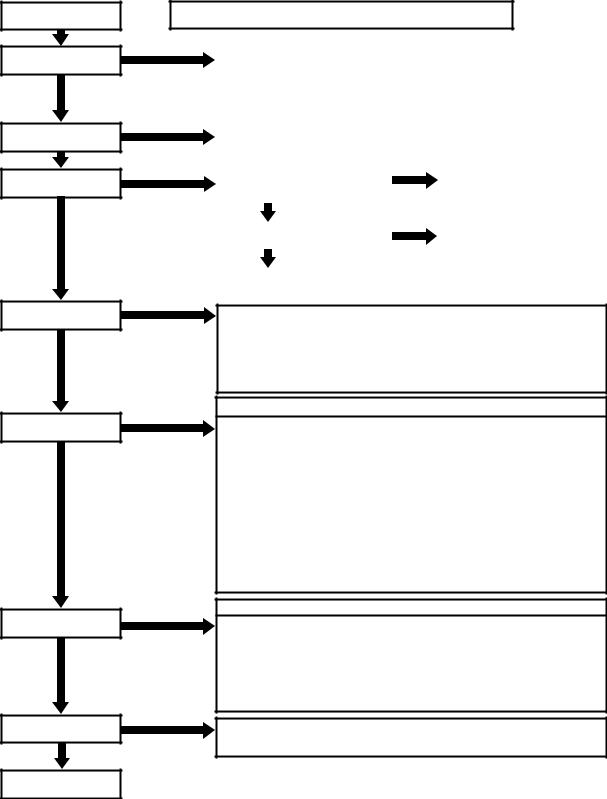
START
TURN THERMOSTAT TO CALL FOR HEAT
DOES S8910U GET POWER (24 VAC NOMINAL)?
YES
30 SECOND MINIMUM PURGE
YES
IGNITER WARMS UP AND GLOWS RED
YES
MAIN BURNER LIGHTS
YES
MAIN BURNER REMAINS POWERED AND LIT
YES
SYSTEM RUNS UNTIL CALL FOR HEAT ENDS
YES
CALL FOR HEAT ENDS, SYSTEM SHUTS OFF
YES
TROUBLESHOOTING ENDS
S8910U3000
NOTE: BEFORE TROUBLESHOOTING, BECOME FAMILIAR WITH STARTUP
AND CHECKOUT PROCEDURES.
NO |
• |
CHECK LINE VOLTAGE POWER. |
|
|
|
|
|
|
• |
CHECK LOW VOLTAGE TRANSFORMER. |
|
|
|
|
|
|
• |
CHECK LIMIT CONTROLLER. |
|
|
|
|
|
|
• CHECK AIR PROVING SWITCH (IF USED). |
|
|
|
|
||
|
• |
CHECK THERMOSTAT. |
|
|
|
|
|
|
• |
CHECK WIRING. |
|
|
|
|
|
NO |
|
|
|
|
|
|
|
|
|
|
|
|
|
||
|
• CHECK AIR PROVING SWITCH. |
|
|
|
|
||
|
• REPLACE S8910U. |
|
|
|
|
||
|
|
|
|
|
|
|
|
NO |
|
|
NO |
|
|||
CONFIRM THAT 120V HOT LEAD |
CHECK AND CORRECT WIRING FUSE |
||||||
|
|
|
|||||
|
CONNECTS TO L1, AND 120V NEUTRAL |
|
|
||||
|
|
|
OR CIRCUIT BREAKER. |
||||
|
LEAD CONNECTS TO L2. |
|
|
||||
|
|
|
|
|
|||
|
|
|
|
|
|
|
|
|
|
YES |
|
|
|
|
|
|
|
|
NO |
|
|
||
|
CHECK FOR 120 VAC ACROSS HOT |
|
REPLACE S8910U. |
||||
|
|
|
|||||
|
SURFACE IGNITER TERMINALS. |
|
|
||||
|
|
|
|
|
|||
|
|
|
|
|
|
|
|
|
|
YES |
|
|
|
|
|
|
|
|
|
|
|
||
|
CHECK WIRES TO IGNITER. |
|
|
|
|
||
|
IF OK, REPLACE IGNITER. |
|
|
|
|
||
|
|
|
|
|
|
|
|
NO
•CHECK FOR 24 VAC ACROSS VALVE TERMINALS ON S8910U DURING TRIAL FOR IGNITION TIMING. IF NO VOLTAGE, REPLACE S8910U.
•CHECK ELECTRICAL CONNECTIONS BETWEEN S8910U AND GAS CONTROL.
IF OK, REPLACE GAS CONTROL.
•CHECK IGNITER POSITION.
•CHECK GAS PRESSURE TO MAIN BURNER.
NOTE: IF S8910U GOES INTO LOCKOUT, RESET SYSTEM.
NO
•CHECK CONTINUITY OF GROUND WIRE AND GROUND PATH FROM MAIN BURNER TO GND (BURNER) TERMINAL OF S8910U.
•CONFIRM THAT 120 VAC HOT LEAD IS CONNECTED TO L1 AND 120 VAC NEUTRAL LEAD IS CONNECTED TO L2.
•CHECK THAT BURNER FLAME COVERS IGNITER/SENSOR OR SENSOR.
•CHECK INSULATION ON IGNITER/SENSOR LEADS.
•CHECK IGNITER/SENSOR OR FLAME ROD FOR CONTAMINATION OR DAMAGE. REPLACE, IF NECESSARY.
•CHECK INSULATION ON SENSOR LEADS AND CHECK SENSOR POSITION. IF CHECKS ARE OK, REPLACE S8910U MODULE.
NOTE: SYSTEM FAILURE AFTER MAIN FLAME LIGHTS HAS A LOW PROBABILITY OF BEING THE S8910U.
NOTE: IF S8910U GOES INTO LOCKOUT, RESET SYSTEM.
NO
•CHECK CONTINUITY OF GROUND WIRE.
NOTE: IF GROUND IS POOR OR ERRATIC, SHUTDOWNS CAN OCCUR OCCASIONALLY EVEN THOUGH OPERATION IS NORMAL AT THE TIME OF CHECKOUT.
•CHECK FOR EXCESSIVE HEAT AT IGNITER OR FLAME ROD CERAMIC BASE (TEMPERATURE ABOVE 1000F (538C) CAUSES SHORT TO GROUND).
•IF CHECKS ARE OKAY, REPLACE S8910U MODULE.
NOTE: SYSTEM FAILURE DURING A RUN CYCLE HAS A LOW PROBABILITY OF BEING THE S8910U.
NO
•CHECK FOR PROPER TEMPERATURE CONTROLLER OPERATION.
•REMOVE VALVE LEAD AT S8910U; IF VALVE CLOSES, RECHECK TEMPERATURE CONTROLLER AND WIRING; IF NOT, REPLACE GAS CONTROL.
REPEAT PROCEDURE UNTIL TROUBLE-FREE OPERATION IS OBTAINED. |
M8531B |
Fig. 7. S8910U troubleshooting sequence.
19 |
34-00008EFS—01 |

S8910U3000
Flame Current Measurement
Flame current of the device can be meaured using a standard micro-ammeter by simply inserting the meter probes into the holes labeled FLAME CURRENT, as shown in Fig. 8.
—Flame current must be measured with valve lit.
—Set meter to DC μAmp scale.
—Ensure meter leads are positioned correctly [+/-].
S8910U HOT SURFACE IGNITER CONTROL
Recommended Minimum Flame Current:
•Must read steady 1 μAmp DC minimum.
•Flame current should be 2 μAmp or greater for reliable appliance operation.
 WARNING
Explosion Hazard. Can cause serious injury or death.
Disconnect power before servicing. This device can malfunction if it gets wet. Never try to use a device that has been wet -- replace it.
BURNER (GND) |
24V (GND) |
VALVE |
|
|
|
|
|
|
|
|
|
|
|
|
|
|
Golden Valley, MN 55422 |
||||||
|
|
|
|
|
|
|
|
|
|
|
|
|
|
Assembled in Mexico |
||||||
|
S8910U Hot Surface Ignition |
|
Selection Tab |
|
|
|
|
|||||||||||||
|
|
|
|
|
|
|||||||||||||||
|
Input Voltages = 120 & 24 VAC, 60 Hz |
|
|
|
|
|
Trial count |
|
|
|||||||||||
|
HSI = 120V, 5A max. |
|
|
|
|
ON |
|
|
|
|
|
|||||||||
|
Valve = 24V, 2A max. |
|
|
|
OFF |
|
|
|
= 1 try (default) |
|||||||||||
|
|
|
|
|
|
|
||||||||||||||
|
Total 24V Load = 0.4 + valve load |
|
ON |
|
|
|
Trial count |
|
|
|||||||||||
|
U.S. Patent 8,085,521 |
|
|
|
OFF |
|
|
|
= 3 tries |
|
|
|||||||||
|
|
|
|
|
|
|
|
|
||||||||||||
|
Prepurge Time = 32 Sec. |
|
|
|
|
ON |
|
|
|
Trial for ign. period |
||||||||||
|
Igniter Warm Up Time = See Inst. Sh. 34-00008 |
OFF |
|
|
|
= 4 seconds (default) |
||||||||||||||
|
Ignition Trial Time - See Selection Tab |
|
ON |
|
|
|
Trial for ign. period |
|||||||||||||
|
Number of Trials - See Selection Tab |
OFF |
|
|
|
= 7 seconds |
||||||||||||||
|
1 2 3 4 |
|||||||||||||||||||
|
Between Trial Time - 96 Sec. |
|
|
|
|
|
|
120 VAC |
|
|||||||||||
|
|
|
|
|
|
See |
NOTE: ALWAYS apply |
|
|
|
|
|
|
|
||||||
(GND) |
|
|
-THW |
|
LED |
this control as instructed |
|
VALVE |
|
|
NEUTRAL |
|
||||||||
|
|
|
LED |
SYSTEM SETUP |
|
|
|
L2 |
HSI |
|
||||||||||
|
|
|
|
|
States |
in Instruction Sheet |
|
|
|
|
|
|
|
|
|
|||||
|
|
|
|
|
|
|
|
|
34-00008 |
|
|
|
|
|
|
|
|
|
|
|
|
|
|
|
|
|
|
|
|
|
|
|
|
|
|
|
|
|
|
|
|
|
|
|
|
|
|
|
|
|
|
|
|
|
|
|
|
|
|
|
|
|
|
|
|
|
|
|
|
|
|
|
|
|
|
|
|
|
|
|
|
|
|
|
|
|
|
|
|
|
|
|
|
|
|
|
|
|
|
|
|
|
|
|
|
|
|
|
|
|
|
|
|
|
|
|
|
|
|
|
|
|
|
|
|
|
|
|
|
|
|
|
|
|
|
|
|
|
|
|
|
|
|
|
|
|
LED States
Control Status |
|
Color |
Pattern |
|
|
|
|||||
Device damaged- |
|
Red |
Steady |
|
|
|
|||||
replace control |
|
|
|
|
|
|
|
|
|||
Ignition lockout |
|
Red |
Blink |
|
|
® |
|||||
Normal operation |
|
Green |
Steady |
C |
US |
||||||
Weak flame signal |
|
Green |
Blink |
AUTO |
|
||||||
See Instruction Sheet 34-00008 |
IGNITION |
||||||||||
SYSTEMS |
|||||||||||
for additional states |
|
|
ANSI Z21.20 |
||||||||
|
|
|
|
|
|
|
32304204-001 Rev. A |
||||
|
120 VAC |
|
See |
|
|
|
|||||
|
HOT |
|
SENSE |
|
|||||||
|
|
Rod |
|
||||||||
|
L1 |
HSI |
|
|
|||||||
|
|
|
|
|
Instructions |
|
|
|
|||
|
|
|
|
|
for |
|
|
|
|||
|
|
|
|
|
Single/Dual |
|
|
|
|||
|
|
|
|
Applications |
|
|
|
||||
|
|
|
|
|
|
|
|
|
|
|
|
|
|
|
|
|
|
|
|
|
|
|
|
|
|
|
|
|
|
|
|
|
|
|
|
|
|
|
|
|
|
|
|
|
|
|
|
DC
002.3 µA
M31283A
Fig. 8. Measuring flame current with micro-ammeter.
Automation and Control Solutions
Honeywell International Inc. 1985 Douglas Drive North Golden Valley, MN 55422 customer.honeywell.com
® U.S. Registered Trademark
© 2015 Honeywell International Inc.
34-00008EFS—01 M.S. 06-15
Printed in United States
S8910U3000
MODULE D'ALLUMAGE PAR INCANDESCENCE UNIVERSEL
NOTICE D’INSTALLATION
L'installation de ce produit doit être réalisée par un technicien d'entretien formé et qualifié.
APPLICATION
Le module d'allumage par incandescence universel S8910U est conçu pour remplacer facilement un vaste éventail de modules d'allumage par incandescence fabriqués par Honeywell, Robertshaw et White-Rodgers. Le module S8910U contrôle le fonctionnement d'un système à allumage direct faisant appel à un allumeur par incandescence de 120 V c.a. Le modèle S8910U remplace les modules d’allumage à veilleuse intermittente et redressement de flamme existants par les caractéristiques suivantes :
•Éléments d'allumage par incandescence à réchauffage temporisé 120 V c.a. (jusqu'à 5 A).
•Allumage par incandescence à électrode unique (détection locale) ou à deux électrodes (détection à distance).
•Un ou trois essais d'allumage par appel de chaleur.
•Essais d'allumage de quatre secondes ou sept secondes.
•Prébalayage de 32 secondes ou moins.
•Durées de balayage entre essais jusqu'à 96 secondes (mode trois essais uniquement).
•Gaz naturel ou GPL.
Le modèle S8910U n'est pas destiné à remplacer les systèmes suivants :
•Modules d'allumage à veilleuse intermittente.
•Modules d'allumage à étincelles direct.
•Modules d'allumage par incandescence 120 V c.a. avec vérification.
•Modules d'allumage par incandescence avec élément 24 V c.a.
•Modules d'allumage par incandescence entrée 240 V c.a./ avec élément. 120 V c.a.
•Modules d'allumage par incandescence 120 V c.a. à réchauffage temporisé de 120 V c.a
—Temps d'essai d'allumage inférieur à quatre secondes.
—Temps d'essai d'allumage supérieur à douze secondes.
—Connecteurs plats au lieu de connecteurs rapides mâles.
Le système S8910U contient le contrôleur S8910U, un mode d'emploi simple et les accessoires requis pour assurer la compatibilité avec le module d'allumage par incandescence existant. Le sac des accessoires comprend un adaptateur White-Rodgers, un fil de terre Robertshaw, quatre connecteurs rapides 0,032 femelles 1/4 po, un connecteur rapide 0,032 femelle 3/16 po et neuf étiquettes de câblage. Les étiquettes de câblage sont incluses pour permettre un marquage adéquat des fils attachés au module existant.
Une liste complète des modules Honeywell et d’autres marques pouvant être remplacés par le modèle S8910U est fournie dans les Tableaux 1 à 3.
REMARQUE : Le modèle S8910U est destiné à remplacer les contrôleurs d'allumage défectueux uniquement. Le technicien d'entretien doit s'assurer que les autres composants de l'appareil et du système de contrôle fonctionnent correctement et de manière fiable avant de remplacer le contrôleur d'allumage.
 AVERTISSEMENT
RISQUE D’EXPLOSION. PEUT CAUSER DES BLESSURES ET DES DOMMAGES MATÉRIELS.
Le modèle S8910U ne peut être utilisé que pour un remplacement direct. Consulter les Tableaux 1 à 3 avant de remplacer un module par incandescence existant par le modèle S8910U. Si le module existant n'est pas répertorié, ne pas utiliser le modèle S8910U pour le remplacer. Toujours consulter le tableau des correspondances pour assurer un réglage correct des commutateurs DIP.
Caractéristiques électriques :
Tension du contrôleur : 24 V, 60 Hz.
Intensité maximale des contacts de vanne : 2 A. Appel de courant : 0,4 A plus charge de la vanne.
Tension de l'allumeur par incandescence : 120 V c.a., 60 Hz. Tension nominale des contacts à 120 V c.a.: 5 A.
IMPORTANT
Le modèle S8910U est conçu pour les applications de 60 Hz. Les temporisations varient de 20 % pour les applications de 50 Hz.
Allumeur par incandescence ou allumeur-capteur :
Modèle Norton 201 ou 271 ou équivalent.
REMARQUE : Si un allumeur autre que le modèle Norton 201 ou 271 est utilisé, il doit être conforme aux caractéristiques minimales suivantes requises pour toute la durée d'utilisation de l'allumeur
•L'allumeur doit atteindre 1000 °C (1832 °F) dans la période de réchauffage sélectionnée de 7, 17, 34 ou 45 secondes à 102 V c.a.
Loading...