


S8610U
Universal Intermittent Pilot Module
PRODUCT DATA
APPLICATION
The S8610U Universal Replacement Ignition Module is designed to provide easy field replacement of a wide range of intermittent pilot ignition modules manufactured by Honeywell, Robertshaw, Johnson and others. The S8610U Module provides ignition sequence, flame monitoring, and safety shutoff for intermittent pilot central furnaces, residential boilers, and other heating appliances.
FEATURES
•Provides up to 1.0A pilot and 2.0A main valve current rating.
•System uses rectification principle for flame sensing.
•For use with separate igniter and sensor or combination igniter-sensor. Q345, Q348, Q362, Q373 or Q381 Igniter-sensor recommended as combination igniter-sensor; Q179C with igniter and sensor mounted on one bracket, or Q354 Sensor with Q345, Q348, Q362, Q373 or Q381 Igniter-sensor recommended as separate igniter and sensor.
•Q3450/Q3480 Hot Surface Pilot hardware plugs directly into system control.
•Can be used on natural or LP gas; provides 100 percent shutoff on ignition failure. Waits six minutes nominal following shutoff, then reinitiates the pilot ignition sequence. The ignition trial-shutoff-wait cycle repeats until the pilot lights or the call for heat ends.
•Replaces numerous Honeywell and competitor modules.
•Capacitive discharge spark output.
•Temperature rating is -40°F to 175°F (-40°C to 79°C) when used with 1.0A or less main valve; -40°F to 165°F (-40°C to 74°C) when used with 1.0 to 2.0A main valve.
|
Contents |
Application ........................................................................... |
1 |
Features .............................................................................. |
1 |
Specifications ...................................................................... |
2 |
Ordering Information ........................................................... |
2 |
Planning the Installation ...................................................... |
4 |
Installation ........................................................................... |
6 |
Startup and Checkout ......................................................... |
15 |
Maintenance ........................................................................ |
15 |
Operation ............................................................................ |
16 |
Troubleshooting .................................................................. |
17 |
ANSI Standards .................................................................. |
21 |
® U.S. Registered Trademark |
|
Copyright © 1996 Honeywell Inc. • All Rights Reserved |
68-0135-2 |

S8610U UNIVERSAL INTERMITTENT PILOT MODULE
SPECIFICATIONS
IMPORTANT
The specifications given in this publication do not include normal manufacturing tolerances. Therefore, units may not exactly match the listed specifications Also, units are tested and calibrated under closely controlled conditions, and some minor differences in performance can be expected if those conditions are changed.
SUPER TRADELINE® Models
SUPER TRADELINE® models are selected and packaged for ease of handling, ease of stocking, and maximum replacement value. SUPER TRADELINE® model specifications are the same as those of standard models except as noted.
SUPER TRADELINE® Model Available:
S8610U Universal Intermittent Pilot Module.
Electrical Ratings:
Voltage: 24V, 60 Hz.
Current Draw: 1A pilot valve, 2A main valve. Valve Contact Rating: 0.2A.
Trial for Ignition:
90 seconds maximum, then 100% shutoff (pilot and main gas).
Continuous Retry:
Five-minute minimum (six-minute nominal) delay if pilot fails to light during trial for ignition. After delay, trial for ignition is repeated. This sequence (trial, delay, trial, delay) continues until pilot lights or call for heat ends.
Spark Generator Output:
13 kV peak at 25 pF load.
Thermostat Anticipator Setting:
0.2A plus pilot valve rating plus main valve rating.
Ambient Temperature Rating:
-40°F to +175°F (-40°C to +79°C) with main valve rated 1.0A or less.
-40°F to +165°F (-40°C to +74°C) with main valve rated 1.0A to 2.0A.
Relative Humidity Rating:
5 to 90% RH at 95°F.
Flame Failure Response Time:
0.8 sec at 1.0 mA flame current.
Terminals:
SENSE: 3/16 in. male quick connect.
All Other Terminals Including Ignition: 1/4 in. male quick connects. Molex plug for connection to Honeywell D80D or D892 Vent Damper.
Flame Current:
1 uA minimum.
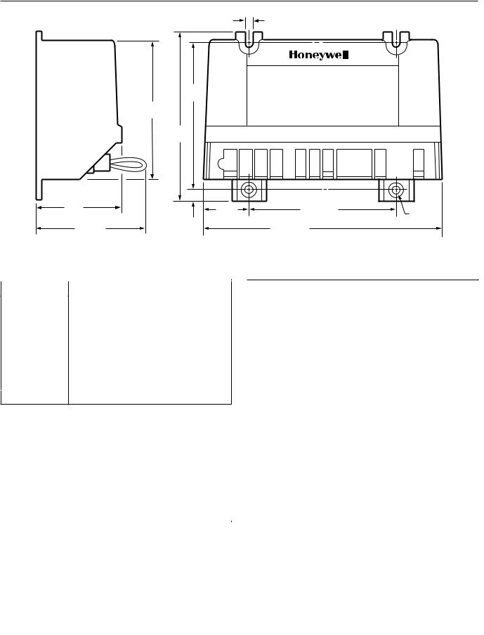
Mounting:
Mounts in any position except with terminals up. However, recommended mounting position is with terminals down to provide maximum protection from dripping water or dust accumulation. Fasten with no. 6-32 machine or no. 8 sheetmetal screws of appropriate length. See Fig. 1.
Underwriters Laboratories Inc. Component Recognized:
File no. MH15564, Guide no. MCCZ2.
IAS Design Certified: C2030011.
Other System Components
These modules provide operating control of an intermittent pilot system. Additional components required to complete the system must be ordered separately:
•Dual valve combination gas control designed for intermittent pilot.
•Combination pilot burner/igniter-sensor or separate igniter and sensor on pilot burner bracket.
•Ignition cable.
•Transformer.
•24V thermostat.
•High limit and other auxiliary controls, as required.
Dual Valve Combination Gas Control:
Any that meet current ratings listed below. VR8204, VR8440 or VR8520 are recommended.
S8610U: 1.0A pilot, 2.0A main valve.
Pilot Burner/Igniter-Sensor:
See Table 1.
ORDERING INFORMATION
When purchasing replacement and modernization products from your TRADELINE® wholesaler or distributor, refer to the TRADELINE® Catalog or price sheets for complete ordering number, or specify:
1.SUPER TRADELINE® order number.
If you have additional questions, need further information, or would like to comment on our products or services, please write or phone:
1.Your local Home and Building Control Sales Office (check white pages of your phone directory).
2.Home and Building Control Customer Logistics Honeywell Inc., 1885 Douglas Drive North Minneapolis, Minnesota 55422-4386
In Canada—Honeywell Limited/Honeywell Limitée, 35 Dynamic Drive, Scarborough, Ontario M1V 4Z9.
International Sales and Service Offices in all principal cities of the world. Manufacturing in Australia, Canada, Finland, France, Germany, Japan, Mexico, Netherlands, Spain, Taiwan, United Kingdom, U.S.A.
68-0135—2 |
2 |
S8610U UNIVERSAL INTERMITTENT PILOT MODULE
3/16 (2)
(5)
3-3/8
(86)
3-3/16
(81)
3-15/16
(100)
2 (51) |
1-1/32 |
3-3/8 (86) (2) |
|
|
(26) |
3/16 |
(2) |
|
1/4 |
(5) |
|
|
|
|
|
2-5/8 (67) |
(6) |
5-7/16 (138) |
|
|
|
M1123A |
|
Fig. 1. Approximate ignition module dimensions in in. (mm).
Table 1. Pilot Burner/Igniter-Sensors.
|
|
|
|
|
Pilot Burner/ |
Flow Rate* |
|
|
Igniter-Sensor |
cfh |
m3/hr |
Combined |
Q345 |
0.8 |
0.02 |
|
Q348 |
1.5 |
0.04 |
|
Q362 |
0.5 |
0.014 |
|
Q373 |
0.8 |
0.02 |
|
Q381 |
0.5 |
0.014 |
|
|
|
|
Separate |
Q179C |
1.8 |
0.05 |
|
|
|
|
Q354 with Q345, Q348, Q362 or Q381.
*With natural gas at 7.0 in. wc (1.7 kPa).
Ignition Cable:
Use Honeywell preassembled cable, see Table 2, or assemble locally. Use the cable recommended in Table 3 (or equivalent), insulated female 1/4 in. quick connect and insulated Rajah connector receptacle. Maximum recommended length is 36 in. (914 mm).
Table 2. Honeywell Preassembled Ignition Cables
(UL Style 3257).
|
|
|
|
Cable |
|
|
|
Part |
|
Module |
|
Number |
Length |
End |
Igniter End |
|
|
|
|
394800-30 |
30 in. |
1/4 in. quick |
Rajah connector |
|
|
connect, |
receptacle, 90 |
|
|
insulated |
degree rubber |
|
|
|
boot |
|
|
|
|
394801-30 |
30 in. |
1/4 in. quick |
Rajah connector |
|
|
connect, |
receptacle, straight |
|
|
insulated |
rubber boot |
|
|
|
|
Table 3. Recommended Ignition Cable for Field Assembly.
|
Voltage |
Temperature Rating |
|
Cable Type |
Rating (rms) |
°C |
°F |
|
|
|
|
UL Style 3217 |
10,000 |
150 |
302 |
|
|
|
|
UL Style 3257 |
10,000 |
250 |
484 |
|
|
|
|
Transformer:
Add current ratings of module, pilot valve, main valve, vent damper and any other components of the control system to determine transformer-size requirement. Use a 30 VA or larger transformer if a vent damper will be connected to the S8610U Vent Damper Connector.
Thermostat:
Use open-close switch type, or independently-powered electronic, 24V thermostat capable of switching rated control system load. Before using electronic thermostat powered through the heating/cooling controls, consult thermostat manufacturer to assure proper control system operation.
High Limit and Other Auxiliary Controls:
As specified by the heating appliance manufacturer.
Ignition Modules Replaced
 WARNING
Check Table 4 before replacing an existing intermittent pilot module with the S8610U. If the existing module is not listed, do not use the S8610U to replace it unless you are certain the specifications of the S8610U match those of the existing module.
3 |
68-0135—2 |

S8610U UNIVERSAL INTERMITTENT PILOT MODULE
The S8610U replaces existing flame rectification type intermittent pilot ignition modules with the following characteristics:
•Single rod (local sense) or two rod (remote sense) flame sensing.
•Non-100 percent shutoff, 100 percent shutoff/lockout, or 100 percent shutoff/continuous retry.
•Natural or LP gas.
•Shutoff/lockout times of 30 seconds or longer.
•Prepurge times of four seconds or shorter.
•Pilot burners with flow rates of 1500 Btuh or less.
•With or without vent dampers.
A complete list of the specific Honeywell and other modules that the SUPER TRADELINE® S8610U is designed to replace is provided in Table 4.
The S8610U SUPER TRADELINE® package contains complete, easy-to-use instructions, plus the accessories required to adapt the existing spark cable (Rajah, stud, nail, or other) to the spark terminal on the S8610U. It also provides labels to help assure proper marking of the wires attached to the existing module.
The S8610U SUPER TRADELINE® Universal Module is not designed to replace controls with the following characteristics:
•Flame sensing other than by flame rectification (White Rodgers Cycle-Pilot®, Robertshaw thermal sensing).
•Flame rectification modules with shutoff/lockout times of less than 30 seconds, prepurge times of more than four seconds, or pilot burners larger than 1500 Btuh.
•Standing pilot appliances.
Honeywell provides additional control packages to accomplish these replacements. See the Honeywell Electronic Ignition Service Manual, form 70-6604, or call your Honeywell wholesaler.
PLANNING THE INSTALLATION
 WARNING
FIRE OR EXPLOSION HAZARD
CAN CAUSE PROPERTY DAMAGE, SEVERE INJURY OR DEATH.
Follow these warnings exactly:
1.Plan the installation as outlined below.
2.Plan for frequent maintenance as described in the Maintenance section.
When intermittent pilot systems are used on central heating equipment in barns, greenhouses, and commercial properties and on heating appliances such as commercial cookers, agricultural equipment, industrial heating equipment and pool heaters, heavy demands are made on the controls. Special steps may be required to prevent nuisance shutdowns and control failure due to frequent cycling, severe environmental conditions related to moisture, corrosive chemicals, dust or excessive heat. These applications require Honeywell Home and Building Control Engineering review; contact your Honeywell Sales Representative for assistance.
Review the following conditions that could apply to your specific installation and take the precautionary steps suggested.
Frequent Cycling
These controls are designed for use on appliances that typically cycle three to four times an hour only during the heating season only. In year-round applications with greater cycling rates, the control can wear out more quickly. Perform a monthly checkout.
Water Or Steam Cleaning
If a module or gas control gets wet, replace it. If the appliance is likely to be cleaned with water or steam, protect (cover) the controls and wiring from water or steam flow. Mount the controls high enough above the bottom of the cabinet so they do not get wet during normal cleaning procedures. Use a NEMA 4 enclosure for the ignition module; see the Electronic Ignition Service Manual, form 70-6604.
High Humidity or Dripping Water
Dripping water can cause the module to fail. Never install an appliance where water can drip on the controls.
In addition, high ambient humidity can cause the gas control to corrode and fail.
If the appliance is in a humid atmosphere, make sure air circulation around the controls is adequate to prevent condensation. Also, regularly check out the system. A NEMA 4 enclosure is recommended for the ignition module; see the Electronic Ignition Service Manual, form 70-6604.
Corrosive Chemicals
Corrosive chemicals can attack the module and gas control, eventually causing a failure. If chemicals are used for routine cleaning, make sure they cannot reach the controls. Where chemicals are suspended in air, as in some industrial or agricultural applications, use a NEMA 4 enclosure for the ignition module; see the Electronic Ignition Service Manual, form 70-6604.
Dust or Grease Accumulation
Heavy accumulations of dust or grease can cause controls to malfunction. Where dust or grease can be a problem, provide covers for the module and the gas control to limit contamination. A NEMA 4 enclosure is recommended for the ignition module; see the Electronic Ignition Service Manual, form 70-6604.
Heat
Excessively high temperatures can damage controls. Make sure the maximum ambient temperature at the control does not exceed the rating of the control. If the appliance operates at very high temperatures, use insulation, shielding, and air circulation, as necessary, to protect the controls. Proper insulation or shielding should be provided by the appliance manufacturer; verify that proper air circulation is maintained when the appliance is installed.
68-0135—2 |
4 |

S8610U UNIVERSAL INTERMITTENT PILOT MODULE
Table 4. S8610U Replaces these Ignition Modules.
CAMSTAT |
S86H1089 |
CSA42A-604R |
IPI-24-00 |
S86H1097 |
CSA43A-600R |
FENWAL |
S86H1105 |
CSA44A-600R |
S86H1121 |
CSA45A-601R |
|
05-203025-005 |
S86H1147 |
CSA45A-602R |
05-203026-005 |
S90A100 |
CSA46A-600R |
HONEYWELL |
S90B1003 |
CSA48A-600R |
S90B1011 |
CSA49A-600R |
|
S86A1001 |
S8600A1001 |
CSA49A-605R |
S86A1019 |
S8600B1009 |
CSA51A-601R |
S86A1027 |
S8600C1015 |
CSA52A-600R |
S86A1035 |
S8600F1000 |
G60AAA-1 |
S86B1009 |
S8600F1034 |
G60AAG-1 |
S86B1017 |
S8600F1042 |
G60AAG-3 |
S86B1025 |
S8600H1006 |
G60AAG-4 |
S86C1007 |
S8600H1022 |
G60AAG-5 |
S86C1015 |
S8600H1048 |
G60AAG-6 |
S86C1031 |
S8600H1055 |
G60CAA-1 |
S86C1049 |
S8600H1089 |
G60CAA-3 |
S86C1056 |
S8600H1105 |
G60CAG-1 |
S86D1005 |
S8600M1005 |
G60CAG-2 |
S86D1021 |
S8600M1013 |
G60CAG-3 |
S86E1002 |
S8610A1009 |
G60CAG-4 |
S86E1010 |
S8610B1007 |
G60CAG-5 |
S86E1028 |
S8610B1015 |
G60CAG-6 |
S86E1036 |
S8610C1005 |
G60CAG-7 |
S86E1044 |
S8610F1008 |
G60CAG-8 |
S86E1051 |
S8610F1016 |
G60CAG-9 |
S86E1069 |
S8610F1024 |
G60CBA-1 |
S86E1077 |
S8610F1032 |
G60CBA-3 |
S86E1101 |
S8610H1012 |
G60CBG-1 |
S86E1119 |
S8610H1038 |
G60CBG-10 |
S86E1127 |
S8610H1046 |
G60CBG-11 |
S86F1000 |
S8610H1053 |
G60CBG-14 |
S86F1018 |
S8610H1079 |
G60CBG-16 |
S86F1026 |
S8610M1003 |
G60CBG-17 |
S86F1042 |
S8610M1029 |
G60CBG-3 |
S86F1059 |
S8620H1028 |
G60CBG-4 |
S86F1067 |
HSC |
G60CBG-9 |
S86F1075 |
G60CCA-1 |
|
S86F1083 |
1003-3 |
G60CCG-1 |
S86F1091 |
1003-300 |
G60CPG-1 |
S86G1008 |
|
G60DBG-1 |
S86G1016 |
PENN- |
G60DCG-1 |
S86G1032 |
JOHNSON |
G60DCG-2 |
S86G1057 |
CSA35A-617R |
G60PAG-1 |
S86G1073 |
CSA35A-618R |
G60PAG-2 |
S86H1006 |
CSA42A-600R |
G60PAG-3 |
S86H1022 |
CSA42A-601R |
G60PAG-4 |
S86H1048 |
CSA42A-603R |
G60PAG-5 |
|
|
|
G60PAG-6 |
G60RCG-2 |
G67AG-7 |
G60PAJ-1 |
G60RCJ-1 |
G67AG-8 |
G60PAK-1 |
G60RDG-1 |
G67BG-2 |
G60PAK-2 |
G60RDK-1 |
G67BG-3 |
G60PFH-1 |
G60RGL-1 |
G67BG-4 |
G60PFH-2 |
G60RHL-1 |
G67BG-5 |
G60PFL-1 |
G60RHP-1 |
G67MG-1 |
G60PFQ-1 |
G60RPL-1 |
G67MG-4 |
G60PVL-1 |
G60RSL-1 |
G67NG-2 |
G60QAG-2 |
G60ZAG-1 |
G600AX-1 |
G60QAG-3 |
G65BBG-1 |
G600AY-1 |
G60QAK-1 |
G65BBG-2 |
G600MX-1 |
G60QBG-1 |
G65BBG-3 |
G600NX-1 |
G60QBG-2 |
G65BBG-4 |
G600RX-1 |
G60QBG-3 |
G65BBG-5 |
G670AW-1 |
G60QBG-4 |
G65BBG-6 |
G770MGA-1 |
G60QBG-5 |
G65BBG-7 |
G770MGA-2 |
G60QBG-6 |
G65BBG-8 |
G770MGC-1 |
G60QBG-7 |
G65BBM-1 |
G770MGC-2 |
G60QBG-8 |
G65BBM-2 |
G770MGC-3 |
G60QBG-9 |
G65BBM-3 |
G770MHA-1 |
G60QBH-1 |
G65BBM-4 |
G770NGA-1 |
G60QBK-1 |
G65BCG-1 |
G770NGC-4 |
G60QBK-3 |
G65BCM-1 |
G770NGC-5 |
G60QBL-1 |
G65BFG-1 |
G770NGC-6 |
G60QBL-2 |
G65BFM |
G770NGC-7 |
G60QCG-1 |
G65BKG-1 |
G770RGA-1 |
G60QCJ-1 |
G65BKG-2 |
G770RHA-1 |
G60QCL-1 |
G65BKG-3 |
G770MHA-2 |
G60QDG-1 |
G65BKM-1 |
G770MHC-1 |
G60QFL-1 |
G65BKM-2 |
G770NHA-1 |
G60QHL-1 |
G65BKM-3 |
G770NHC-1 |
G60QJL-1 |
G65DBG |
G770RHA-2 |
G60QLG-1 |
G65DBM-1 |
|
G60QPL-1 |
G65DBM-3 |
|
G60QRH-1 |
G65DCM-1 |
ROBERTSHAW |
G60QRL-1 |
G65DFG |
|
G60QRL-2 |
G65DFM-1 |
780-715 |
G60QRL-3 |
G65DKG |
780-735 |
G60QSL-1 |
G65DKM |
780-737 |
G60QTH-1 |
G65FBG |
SP715 |
G60QTL-1 |
G65FFG |
SP715A |
G60RAG-1 |
G65FKG |
SP735 |
G60RAK-1 |
G66AG-1 |
SP735D |
G60RBG-1 |
G66BG-1 |
SP735L |
G60RBG-2 |
G66MG-1 |
USI 715U |
G60RBG-3 |
G66NG-1 |
|
G60RBK-1 |
G67AG-3 |
|
G60RBK-2 |
G67AG-4 |
|
|
|
|
5 |
68-0135—2 |

S8610U UNIVERSAL INTERMITTENT PILOT MODULE
INSTALLATION
1.Read these instructions carefully. Failure to follow them could damage the components or cause a hazardous condition.
2.Check the ratings given in the instructions and on the components to make sure they are suitable for your application.
3.Installer must be a trained, experienced service technician.
4.After installation is complete, check out component operation as provided in these instructions.
 WARNING
FIRE OR EXPLOSION HAZARD CAN CAUSE PROPERTY DAMAGE, SEVERE INJURY, OR DEATH.
1.If it gets wet, the ignition module can malfunction, leading to accumulation of explosive gas.
•Never install where water can flood, drip or condense on the module.
•Never use a module that has been wet. Replace it.
2.Liquefied petroleum (LP) gas is heavier than air and will not vent upward naturally.
•Do not light the pilot or operate electric switches, lights or appliances until you are sure the appliance area is free of gas.
3.Do not attempt to disassemble or clean the module. Improper reassembly and cleaning can cause unreliable operation.
CAUTION
1.Disconnect the power supply before beginning the wiring to prevent electrical shock or equipment damage.
2.If a new gas control is to be installed, turn off the gas supply before starting the installation. Conduct a Gas Leak Test according to the gas control manufacturer instructions after the gas control is installed.
3.If the module must be mounted near moisture or water, provide a suitable waterproof enclosure.
4.Using the wire labels provided, label all wires before they are disconnected. Wiring errors can cause improper appliance operation and dangerous conditions such as bypassing safety features.
Perform Preinstallation Safety Inspection
The preinstallation checks described in ANSI Standard Z21.71 in Exhibit A must be done before the replacement module is installed. If a condition is detected that could result in unsafe operation, the appliance should be shut off and the owner advised of the unsafe condition. Correct any potentially unsafe condition before proceeding with the installation.
Remove Old Module
Disconnect power supply before doing any work on the unit. Disconnect and tag the wires from the old module using the wire labels provided. Remove the old module from its mounting location.
Mount New Ignition Module
We recommend mounting the S8610U Module in the same location as the old module, if possible. Otherwise, select a location close enough to the burner to allow a short (3 ft (0.9m) maximum) direct cable route to the igniter. Ambient temperature at the module must be within the range listed in the Specifications section.
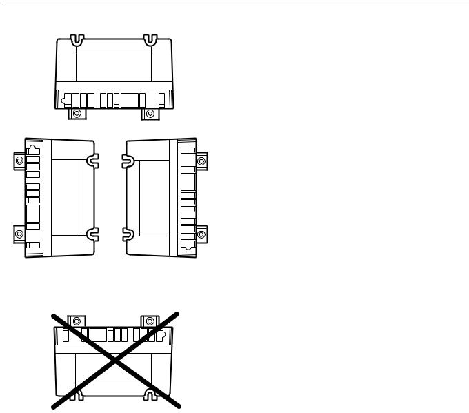
Mount the module with the terminals pointing down to protect them from dripping water and dust. The module can also be mounted with the terminals on either side. Do not mount with terminals pointing up. Refer to Fig. 2 for mounting recommendations. When it is necessary to drill new mounting holes, use the S8610U as a template to mark the mounting hole pattern. Drill new holes as required. Fasten securely with four no. 6-32 machine or no. 8 sheetmetal screws.
Wire the Module
 CAUTION
1.Check the wiring diagram furnished by the appliance manufacturer, if available, and compare with Tables 5 through 8. Carefully follow any special instructions affecting the general procedures outlined below.
2.Disconnect the power supply before making wiring connections to prevent electrical shock or equipment damage.
IMPORTANT
1.A common ground is required on:
a.The pilot burner mounting bracket, and
b.The GND (BURNER) terminal on the ignition module. Failure to use the GND (BURNER) terminal can result in intermittent loss of spark and/or loss of flame current sensitivity.
2.Make sure the transformer has adequate VA. The ignition module requires at least 0.2A at 24 Vac. Add the current draws of all other devices in the control circuit, including the pilot and main valves in the gas control, and multiply by 24 to determine the total VA requirement of these components. Add this total to 4.8 VA (for the ignition module). The result is the minimum transformer VA rating. Use a Class II transformer when replacement is required.
3.When a vent damper is connected to the S8610U vent damper connector, be sure the system transformer delivers at least 30 VA. The S8610U has an internal fuse that is intended to prevent appliance lightoff if the vent damper is not in place or wired properly. Using a small transformer can interfere with the proper operation of the fuse and bypass the intended safety feature.
Connect the wires to the S8610U Ignition Module as shown in Tables 5 through 8. Make sure that adequate system ground is provided as indicated in the wiring tables.
Verify the thermostat anticipator setting as explained in the IMPORTANT above.
68-0135—2 |
6 |
S8610U UNIVERSAL INTERMITTENT PILOT MODULE
MOUNT IN ONE OF THESE POSITIONS
TERMINALS FACING DOWN
TERMINALS FACING LEFT |
TERMINALS FACING RIGHT |
|
|
|
|
|
|
|
DO NOT MOUNT
WITH TERMINALS FACING UP
NOTE: The wiring diagrams in Fig. 5 through 8 show typical hookups for the S8610U Ignition Module and should be used for reference only.
Modify Ignition Cable, If Necessary
Use existing ignition cable if it is in good condition. If the existing ignition cable does not have a 1/4 in. quick-connect on the module end, either use the Rajah adapter or strip the wire and replace with the 1/4 in. insulated quick-connect supplied. If the cable must be replaced, order a Honeywell ignition cable, see Table 2. It may be necessary to replace the connector at the pilot burner end to match the pilot burner spark termination.
NOTE: When using an S8610U to replace an S86, use the enclosed adapter to convert the S86 Ignition Cable to an S8610U Ignition Cable. Then, install the adapter and cable to the S8610U Ignition Module.
NOTE: The cable must not run in continuous contact with a metal surface or spark voltage is greatly reduced. Use ceramic or plastic standoff insulators as required.
M2647
Fig. 2. Module mounting recommendations.
7 |
68-0135—2 |

S8610U UNIVERSAL INTERMITTENT PILOT MODULE
|
|
|
|
|
|
|
|
ProceduralNotes |
|
|
|
|
|
|
theoldmodulehadaventdamper |
S8610U1003. |
|
|
|
|
|
|
|
|
|
|
|
|
|
* Important:If |
|
andS8610to |
OldControl |
S8600F,H,M |
S8610F,H,M |
MV |
MV/PV |
PV |
GND |
(BURNER) |
24VGND |
24V* |
|||||
HoneywellfromConversionS86,S90,S8600 |
S8600A,B,C S8610A,B,C |
S86E,F,G,HS86B,D S90A,B |
MVMV MV |
MV/PVMV/PV MV/PV |
PVPV PV |
GNDGND GND |
(BURNER)(BURNER) |
25V(GND)25V(1)e 24VGND |
25V25V(2) |
||||||
|
|
|
|
|
|
|
|
|
|
|
|
|
|
|
24V* |
|
|
|
|
|
|
|
|
|
|
|
|
|
|
|
e* |
Table5. |
|
|
|
S86A,C |
MV |
MV/PV |
PV |
GND |
|
25V(1) |
25V(2) |
||||
|
|
|
|
|
|
|
|
|
|
|
|
|
|
|
|
|
|
|
|
Replacement |
Control |
|
S8610U1003 |
MV |
MV/PV |
PV |
GND |
(BURNER) |
24V GND |
24V* |
|
|
|
|
|
|
|
|
|
TerminalFunction |
Mainvalveoperator |
Mainvalveandpilot common |
Pilotvalveoperator |
Burnerground |
connection |
Transformer secondary (unswitchedleg) |
Transformer |
|
|
|
|
|
|
|
|
|
|
|
|
|
|
|
|
plugbutaventdamperwasnotinstalled,orifit didnothaveaventdamperplug:leavethevent damperpluginpositionontheS8610and connectthe25V(2)or24Vwirefromtheold moduletotheTH-WterminalontheS8610U. Donotusethe24VterminalontheS8610U. |
Iftheoldmodulehadaventdamperwithaplug |
connection to a Molex connector, wirethe |
terminalsasindicatedinthetable. |
|
25V(2)or24Vusedonlyinsystemswhere |
plug-incableconnectsdampertomodule. |
|
secondary (switched leg)
TH-W
W-TH
a R-TH
a R-TH
a R-TH
W-TH
(This terminal not included on S90.)
TH-Wb TH-W TH-Wb
d
f SENSE
d
d
d
f SENSE
Flame sensor
SPARK SPARK
SPARK
c COILIGN
c COILIGN
c COILIGN
Igniter/sensor SPARK
If 25V (2) and TH-R have wires connected, disconnect and splice together with solderless connector.
a
insulatedquickconnectforconnectiontoS8610. |
wireatcircuitboard,anddiscard. |
IfTH-RandTH-Warejumperedtogether,connect25V(2)leadfromS86toTH-WonS8610U1003. UseRajahtoquickconnectoradapter(supplied)orcutRajahconnectoroffignitioncableatmoduleend;attach |
Leaveblackjumperconnected. Terminalsmaybemarked25Vonsomemodelsand24Vonlatermodels.Thesearefunctionallyequivalent. Ondualigniterandsensormodels,removejumperquickconnectfromS8610U1003Senseterminal,cutjumper |
b c d e f |
|
68-0135—2 |
8 |
 Loading...