


R7184A,B,P,U
Interrupted Electronic Oil Primary
INSTALLATION INSTRUCTIONS
APPLICATION
The R7184A,B,P,U Interrupted Electronic Oil Primary is a line voltage, safety rated, interrupted ignition oil primary control for residential oil fired burners used in boilers, forced air furnaces and water heaters. The R7184A,B,P,U used with a cad cell flame sensor, operates an oil burner and optional oil valve. The primary controls fuel oil, senses flame, controls ignition spark and notifies a remote alarm circuit when in lockout.
lockout timing will be extended to 4 minutes and the ignition set in the intermittent mode for this cycle only. The R7184 automatically reverts to its labeled interrupted and safety switch timing states. The pump priming cycle can only be entered if there have been no lockout occurrences since the last successful heat call. To reset the device so that the pump priming cycle can be entered, press and hold the reset button for 30 seconds until the LED flashes twice.
Disable Function
The R7184 can be used with both hydronic and forced air systems. When used with hydronic systems, line voltage switching Aquastat® Controllers normally provide for the starting and stopping of the combustion sequences. With forced air systems, both mechanical and electronic low voltage thermostats control the starting and stopping of the combustion process.
Some hydronic and forced air systems now require a delayed valve-on and burner motor-off delay. The R7184 operates an oil valve that prevents the flow of oil when the burner motor is running prior to combustion (delayed valve-on) and when the burner motor is running after combustion (burner motor-off delay).
The R7184 models are intended for use only on oil burning appliances which do not require prepurge and post-purge as a safety related function as defined in UL 296. The valve-on delay and burner motor-off delay in this control are intended only to help establish draft and reduce oil after-drip related problems.
Pressing and holding the reset button will disable all functions until the button is released. The R7184 will restart at the beginning of the normal heat cycle on safety check.
Limited Reset (Restricted Mode)
In order to limit the accumulation of unburned oil in the combustion area, the control can only be reset three times. The reset count returns to zero each time a call for heat is successfully completed.
To reset from restricted mode: Press and hold the reset button for 30 seconds. When the LED flashes twice, the device has reset.
SPECIFICATIONS
Models:
Table 1 lists the major features and the applicable wiring diagram numbers for the R7184.
FEATURES
Limited Recycle
This feature limits the number of recycle trials (for each call for heat) to a maximum of three trials. If the flame is lost three times and does not successfully satisfy a call for heat, the R7184 locks out.
Pump Priming Cycle
To facilitate purging air from the oil lines and filters, the R7184 can be placed in a purge routine by pressing and releasing the reset button during the safety check, delayed valve-on , ignition or carry-over periods. The
Timing:
Safe Start Check: 5 seconds (approximately). Valve-on Delay: 15 seconds.
Burner motor-off Delay: 0, 2, 4, or 6 minutes, fieldselectable using DIP switch positions 1 and 2.
NOTE: For universal R7184U model, valve-on delay and burner motor-off delay timings can be enabled (values as listed) or disabled (values are zero) in the field using DIP switch position 3.
Lockout: 15, 30 or 45 seconds (factory-programmed). Recycle: 60 seconds (fixed).
Ignition Carryover: 10 seconds (fixed).
® U.S. Registered Trademark
Copyright © 2000 Honeywell Inc. • All Rights Reserved
69-1233-2
R7184A,B,P,U INTERRUPTED ELECTRONIC OIL PRIMARY
Electrical Ratings:
Inputs:
Voltage: 102 to 132 Vac, 120 Vac nominal.
Current: 100 mA plus burner motor, valve and ignitor loads.
Frequency: 60 Hz. Outputs:
Relay Contacts:
Burner: 120 Vac, 10 full load amperes (FLA), 60 locked rotor amperes (LRA).
Valve: 120 Vac, 1A. Ignitor: 120 Vac, 360 VA. Alarm: 30 Vac, 2A.
Thermostat Current Available: 100 mA.
NOTE: Reduce burner FLA rating by Ignitor load. For example, if the ignitor draws 3A (120 Vac, 360 VA), reduce the burner motor FLA to 7A.
Environmental Ratings:
Operating Ambient Temperature: -40°F (-40°C) to +147°F (+64°C).
Shipping Temperature: -20°F (-29°C) to +150°F (+66°C). Humidity: 90% relative humidity at 95°F (93°C)
noncondensing.
Approvals:
Underwriters Laboratories Inc.: Recognized.
Canadian Underwriters Laboratories Inc.
Table 1. R7184 Models.
|
|
|
|
|
|
|
Valve-on delay |
Burner motor-off |
Alarm |
Typical Wiring Diagram |
Thermostat |
Model |
(sec) |
delay (min) |
Contacts |
Fig. Reference No. |
Terminals T-T |
|
|
|
|
|
|
R7184A |
None |
None |
None |
3,4,5 |
Yes |
|
|
|
|
|
|
R7184B |
15 |
None |
None |
3,6,7 |
Yesc |
R7184Pa |
15 |
0/2/4/6b |
Optional |
3,6,7 |
Yes |
R7184U |
Selectable 0 or 15 |
Selectable 0 or |
Yes |
3,6,7 |
Yes |
|
|
0,2,4,6b |
|
|
|
aSome select models may have a delay enable/disable switch. bStandard timings. Other timing may be available on select models.
cSelect models are provided with a T-T jumper which can be disabled by cutting with a pair of side-cutting pliers.
INSTALLATION
When Installing this Product...
1.Read these instructions carefully. Failure to follow instructions can damage product or cause a hazardous condition.
2.Check ratings given in these instructions and on product to make sure product is suitable for your application.
3.Make sure installer is a trained, experienced service technician.
4.Use these instructions to check out product operation after installation.
 WARNING
Electrical Shock Hazard.
Can cause serious injury or death.
Disconnect power supply before beginning installation to prevent electrical shock or equipment damage.
Location
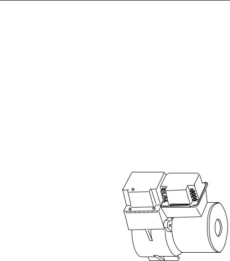
1.Mount on a 4 in. by 4 in. junction box, directly on the main burner or inside the appliance cabinet. In replacement applications, mount in the same location as the old control. See Fig. 1. Make sure the operating temperatures are within the ambient temperature range (see Specifications section).
2.Before mounting the control, make line voltage connections as shown in Fig. 2 through 7. Splice lines with solderless connectors. Do not exceed load ratings shown on the device label.
3.If necessary, use the control as a template to mark and drill new mounting holes.
4.Mount using No. 6 screws (obtained locally).
S7184 |
R7184 |
BURNER
M17180A
Fig. 1. Mounting R7184 on junction box.
WIRING
1.Make sure wiring complies with all local codes and ordinances.
2.After mounting, make low voltage connections to the screw terminals (see Fig. 2 through 7).
3.Strip leads 3/8 in. (10 mm) and insert under terminal screw. See Fig. 1.
4.Connect thermostat leads to T-T.
Switch Settings
Figure 8 and Table 2 provide the switch settings for the R7184U.
69-1233—2 |
2 |

R7184A,B,P,U INTERRUPTED ELECTRONIC OIL PRIMARY
CHECKOUT
Start System
 WARNING
Fire Hazard.
Can cause serious injury or death.
Make sure combustion chamber is free of oil and/or oil vapor before starting system.
 INTERRUPTED
IGNITOR
 INTERMITTENT
BURNER MOTOR
L1
L2
LIMIT
CAD CELL
VALVE
M16453A
Fig. 2. Wiring terminals.
1.Open hand valve in oil supply line.
2.Make sure system is powered. Check circuit breaker or fuse and close system switch, if provided.
3.Set thermostat to call for heat.
4.Make sure burner lights and operates until call for heat ends.
Check Safety Features
Safe Start
1.Place a jumper across cad cell terminals.
2.Follow procedure to turn on burner. Burner must not start, indicator light turns on and control remains in Idle Mode.
Simulate flame failure:
1.Follow procedure to turn on burner.
2.Close hand valve in oil supply line.
3.Device enters recycle mode.
4.Device tries to restart system after approximately 60 seconds.
5.Safety switch locks out approximately in safety switch timing indicated on label. Indicator light flashes at 1 Hz rate. Ignition and motor stop and oil valve closes.
THERMOSTAT |
|
|
|
L8148A,C |
|
|
|
|
C1 |
AQUASTAT® |
|
||
|
CIRCULATION |
L1 |
||||
|
|
|||||
|
C2 |
CONTROLLER |
|
|||
|
PUMP |
|
L2 |
|||
|
|
|
|
|
||
|
|
|
|
|
B2 |
1 |
R |
|
|
|
T |
B1 |
|
|
|
|
|
|||
W |
|
|
|
T |
|
|
R7184 |
|
|
|
|
||
|
|
|
|
|
||
|
T LIMIT |
|
|
|
|
|
|
T |
L1 |
|
|
|
|
|
|
|
|
|
|
|
JUMPER |
|
L2 |
|
|
|
|
|
BURNER MOTOR |
|
BURNER |
|
||
|
|
|
|
MOTOR |
|
|
|
INTERRUPTED |
|
|
|
|
|
|
IGNITOR |
|
|
IGNITOR |
|
|
|
INTERMITTENT |
|
|
|
|
|
|
|
VALVE |
|
VALVE |
|
|
|
|
|
|
|
|
|
TO |
|
|
|
|
|
|
REMOTE |
|
CAD |
|
CAD |
|
|
ALARM 2 |
ALARM |
|
|
|
||
CELL |
|
CELL |
|
|
||
CIRCUIT |
|
|
|
|
||
|
|
|
|
|
|
|
|
|
|
JUNCTION |
|
|
|
|
|
|
BOX |
|
|
|
LEGEND: |
SCREW TERMINAL |
|
1/4 IN. QUICK CONNECT TERMINAL |
|||
1POWER SUPPLY. PROVIDE DISCONNECT MEANS AND OVERLOAD PROTECTION AS REQUIRED.
2 |
OPTIONAL FEATURE ON SELECT MODELS. |
M17182B |
|
Fig. 3. Wiring for typical oil-fired boiler.
T8600 |
|
L1 |
|
(HOT) |
|
|
|
|
|
COOLING |
L2 |
RC |
1 |
|
FAN RELAY |
CONTROL |
|
G |
|
|
|
|
|
Y |
|
R7184 |
|
|
|
R |
|
T |
|
|
1 |
|
|
L1 |
LIMIT |
||
|
|
T |
L1 |
||
W |
|
|
|||
|
|
L2 |
|
HOT |
|
|
|
|
|
L2 |
|
|
|
|
|
|
|
|
|
|
|
VALVE |
3 |
|
|
|
|
|
|
|
|
BURNER |
BURNER |
|
|
|
|
MOTOR |
MOTOR |
|
|
|
|
INTERRUPTED |
IGNITOR |
|
|
|
|
IGNITOR |
|
||
|
|
|
|
||
|
|
INTERMITTENT |
|
|
|
TO |
|
|
CAD |
CAD |
|
REMOTE |
|
|
|
||
|
|
CELL |
CELL |
|
|
ALARM |
2 |
ALARM |
|
||
|
|
|
|||
CIRCUIT |
|
|
|
|
|
|
|
|
|
JUNCTION |
|
|
|
|
|
BOX |
|
LEGEND: |
SCREW TERMINAL |
1/4 IN. QUICK CONNECT TERMINAL |
1POWER SUPPLY. PROVIDE DISCONNECT MEANS AND OVERLOAD PROTECTION AS REQUIRED.
2OPTIONAL FEATURE ON SELECT MODELS.
3 VALVE MAY BE ADDED AS SHOWN. |
M17183B |
Fig. 4. Typical wiring diagram for 24 Vac thermostat and R7184 for an oil-fired forced air system.
3 |
69-1233—2 |
 Loading...