

Page 1

Industrial & Commercial Thermal
AGA
Burner control unit PFU 780
Technical Information · GB
6 Edition 02.12l
• For pilot and main burners of unlimited capacity in
thermoprocessing equipment pursuant to EN 7462
• Separate flame control for pilot burner and main burner by UV,
ionisation or a further option of using the furnace chamber
temperature
• Display of the program status, unit parameters and flame signal;
Manual mode for burner adjustment and for diagnostic purposes
Page 2

Table of contents
Burner control unit PFU 780.........................1
Table of contents ....................................2
1 Application ........................................4
1.1 Examples of application ...........................6
1.1.1 Stage-controlled main burner with alternating
pilot burner ..................................................6
1.1.2 Stage-controlled main burner with permanent
pilot burner ..................................................7
1.1.3 Modulating-controlled burner ........................8
1.1.4 PFU 780..D: High temperature equipment............9
2 Certification ..................................... 10
3 Function ..........................................11
3.1 Connection diagram ..............................11
3.1.1 PFU 780 ..............................................11
3.1.2 PFU 780..K2 .........................................12
3.2 PFU 780 program sequence......................13
3.3 Program status and fault messages..............16
4 Parameters .......................................18
4.1 Scanning the parameters .........................19
4.2 Flame control . . . . . . . . . . . . . . . . . . . . . . . . . . . . . . . . . . . . 20
4.2.1 Flame signal, pilot burner ...........................20
4.2.2 Flame signal, main burner...........................20
4.2.3 Program status when the most recent fault
occurred . . . . . . . . . . . . . . . . . . . . . . . . . . . . . . . . . . . . . . . . . . . . . . . . . . . 20
4.2.4 Switch-off threshold of the flame amplifier.........20
4.2.5 High temperature operation with PFU..D . . . . . . . . . . . .21
4.2.6 UVS check ........................................... 24
4.3 Pilot and main burner monitoring ................25
4.3.1 Permanent pilot burner...............................27
4.3.2 Interrupted pilot burner .............................28
4.4 Behaviour in start-up position/standby ..........29
4.4.1 Flame simulation check in start-up position/
standby ....................................................29
4.4.2 Minimum burner pause time t
4.5 Behaviour during start-up ........................31
....................30
BP
4.5.1 Safety time on start-up tSA ..........................31
4.5.2 Flame proving period t
4.5.3 Minimum combustion time t
4.5.4 Burner start-up at tempts ...........................33
...........................32
FS
......................32
B
4.6 Behaviour during operation.......................35
4.6.1 Safety time during operation tSB for pilot and main
burners ....................................................35
4.6.2 Fault lock-out or restart , pilot burner ...............35
4.6.3 Fault lock-out or restart, main burner ................37
4.7 Air valve control PFU..L ...........................39
4.7.1 Purge.................................................39
4.7.2 Cooling in start-up position/standby ...............39
4.7.3 Burner start ..........................................39
4.7.4 Air valve opens in the case of external activation
(not during start-up).......................................40
4.7.5 Air valve opens in the case of external activation
(even during start-up) ......................................41
4.7.6 Air valve opens with valve V2 ........................ 42
4.7.7 Air valve opens with operating signal ................43
4.7.8 Low fire over run time t
4.7.9 Behaviour of the air valve in the event of a fault
lock-out.................................................... 45
after a normal shut-down 44
KN
4.8 Manual operation ................................ 46
4.8.1 Manual mode limited to 5 minutes..................46
4.9 Password .........................................47
5 Selection ........................................ 48
5.1 Calculating the safety time t
.................. 48
SA
5.2 Selection table ....................................49
5.2.1 Type code............................................49
6 Project planning information .................... 50
6.1 Cable selection .................................. 50
6.1.1 Ignition cable........................................50
6.1.2 Ionisation cable .....................................50
6.1.3 UVLeitung ..........................................50
6.2 Ignition electrode ................................ 50
6.2.1 Electrode gap .......................................50
PFU 780 · Edition 02.12l 2
= To be continued
▼
Page 3

6.2.2 Star electrodes ......................................50
6.3 Minimum combustion time.......................51
6.4 Safety interlocks (Limits) .........................51
6.5 Emergency stop ..................................52
6.5.1 In the event of fire or electric shock . . . . . . . . . . . . . . . . . 52
6.5.2 Via the safety interlocks (limits)..................... 52
6.6 Reset ..............................................52
6.6.1 Parallel reset......................................... 52
6.6.2 Permanent remote reset ............................ 52
6.6.3 Automatic remote reset (PLC) ...................... 52
6.6.4 Burner start ......................................... 52
6.6.5 Restart and start-up attempts ......................52
6.7 Fault message ....................................53
6.8 Protecting the pilot burner from overload ........53
6.9 Installation........................................53
6.10 Wiring............................................53
6.10.1 UVS sensor wiring..................................53
6.11 PFU switched off ................................53
6.12 Furnace control .................................54
6.13 Note on EC type-examination...................54
6.14 Mains switch ....................................54
6.15 Changing parameters ...........................54
7 Flame control .....................................55
7.1 With ionisation sensor ............................55
7.2 With UV sensor ....................................55
7.3 Via the temperature in high temperature
equipment ............................................55
8 Accessories...................................... 56
8.1 High-voltage cable ...............................56
8.2 BCSoft ............................................56
8.3 Stickers for labelling ..............................56
8.4 “Changed parameters” stickers ..................56
8.5 Radio interference suppressed electrode
adapters ..............................................57
8.6 Socket connectors ................................57
8.7 Module subrack ...................................57
8.8 Power supply PFP 700............................58
8.9 Relay module PFR 704 ...........................59
8.10 Field bus interface PFA 700.................... 60
8.11 Impulse system MPT 700 .......................61
9 Technical data ....................................62
9.1 Safety-specific characteristic values .............64
9.2 Operating controls................................65
10 Maintenance cycles ............................ 66
11 Legend ..........................................67
12 Glossary........................................ 68
12.1 Waiting time
tW ..............................68
12.2 Safety time on start-up tSA ..................... 68
12.3 Ignition time t
................................. 68
Z
12.4 Flame simulation/Flame simulation delay
time t
12.5 Safety time during operation t
..........................................68
LV
.............69
SB
12.6 Flame signal .....................................69
12.7 Fault lock-out ....................................69
12.8 Safety interlocks (Limits) ........................69
12.9 Pilot gas valve V1 ................................69
12.10 Main gas valve V2 ..............................69
12.11 Continuous operation..........................70
12.12 Air valve.........................................70
12.13 Diagnostic coverage DC .......................70
12.14 Mode of operation..............................70
12.15 Safe failure fraction SFF .......................70
12.16 Probability of dangerous failure PFH
12.17 Mean time to dangerous failure MT TF
........70
D
.......70
d
Feedback ...........................................71
Contact.............................................71
PFU 780 · Edition 02.12l 3
= To be continued
▼
Page 4

Application
Module subrack
BGT for instance
serves to accommodate several
function units. It
is provided with
a backplane with
screw terminals
for simple, reliable
wiring.
1 Application
The burner control units PFU 780 control, ignite and
monitor gas burners for intermittent or continuous operation. As a result of their fully electronic design they
react quickly to various process requirements and are
therefore also suitable for frequent cycling operation.
The PFU 780 can be used for industrial burners of un-
limited capacity which are ignited by pilot burners. Pilot
and main burners are controlled and monitored independently. This reduces the main burner start-up time.
The pilot burner can burn permanently or be switched
off. The main burners may be modulating or stagecontrolled.
the burner always ignites in a safe condition after it has
been restarted.
The burner control unit is used for burners with me-
chanical combustion air supply where the fan is controlled by a separate logic and for atmospheric burners.
The air valve control on the PFU 780L assists the fur-
nace control for cooling, purging and capacity control
tasks.
The program status, the unit parameters and the level
of the flame signal can be read directly from the unit.
Pilot and main burners can be controlled manually for
commissioning and diagnostic purposes.
▼
On industrial furnaces, the PFU 780 reduces the load
on the central furnace control by taking over tasks that
only relate to the burner, for example it ensures that
PFU 780 · Edition 02.12l 4
Page 5

Application
If the local requirements on the burner control units
change, the PC software BCSoft can be adjusted to the
unit parameters of the application by using the optical
interface.
To support service personnel, BCSoft offers a conveni-
ent visualisation system of the input and output signals
and the error history.
Intermittent shuttle kiln in the ceramics industry
Bogie hearth forging furnace in the metallurgical industry
Walking beam furnace with overhead firing
PFU 780 · Edition 02.12l 5
Page 6

Application
PFU 780
22e
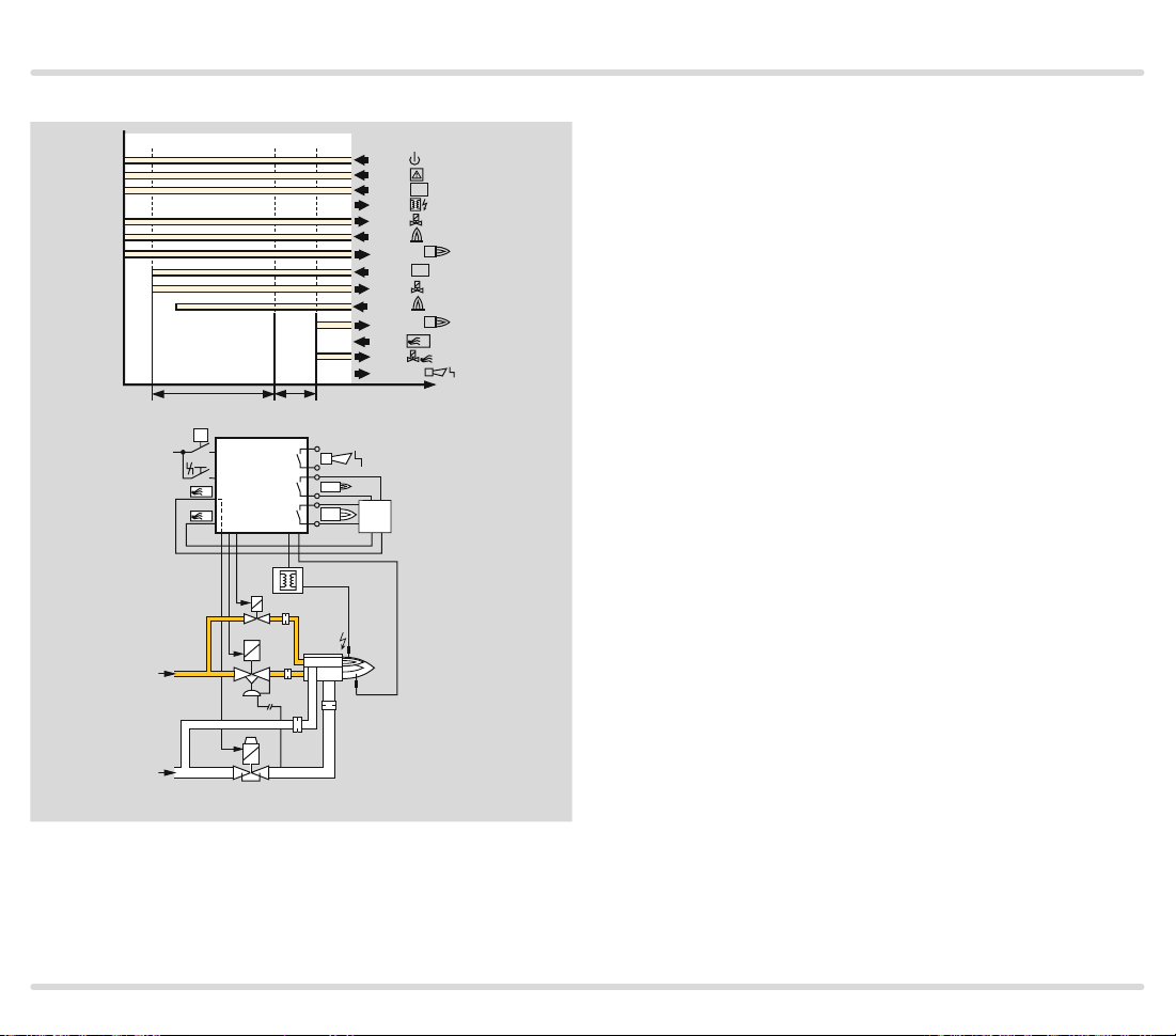
1.1 Examples of application
1.1.1
Stage-controlled main burner
with alternating pilot burner
L1, N, PE
DI
P
SPS
PLC
CPE
DI
26e 10c
22a
A
P
ϑ1
ϑ2
14a 30e 10a
10e
µC
28c 16c 18e
18a
2e
4e
2c
4c
6a
6e
1
2
TZI
VBY
1
2
UV
VAG
Control: Main burner ON/OFF.
The main burner can be started with
reduced capacity after the operating signal from the pilot burner has
been detected. The pilot burner is
switched off automatically after the
main burner has started up. When
the main burner is switched off, the
pilot burner automatically switches
on again.
A UV sensor monitors the flame signal from pilot and main burners. UV
sensor UVD 1 is used for continuous operation, UV sensor UVS for
intermittent operation.
02–04 02–04 06–08 06–08
VR..L
ϑ1
1
ϑ2
2
t
PFU 780 · Edition 02.12l 6
Page 7

Application
PFU 780
22e
1.1.2 Stage-controlled main burner with permanent pilot burner
Control: Main burner ON/OFF.
L1, N, PE
DI
P
SPS
PLC
CPE
DI
26e 10c
22a
A
P
VBY
ϑ1
ϑ2
14a 30e 10a
10e
µC
26a
28c 16c 18e
18a
TZI
1
2
2e
4e
2c
4c
6a
6e
1
2
VAG
The main burner can be started with
reduced capacity after the operating signal from the pilot burner has
been detected. Pilot and main burners can be operated simultaneously.
Both are ionisation-controlled independently.
04 02–04 06–08 06–08
VR..R
04
ϑ1
1
ϑ2
2
t
PFU 780 · Edition 02.12l 7
Page 8

Application
PFU 780
1.1.3
Modulating-c ontrolled burner
Control: Main burner continuous
The butterfly valve for air BV is
moved to ignition position in order
L1, N, PE
DI
P
SPS
PLC
mA
CPE
DI
26e 10c
22a
16c 18e
VBY
28c
TZI
1
26a
ϑ1
µC
2
10e
18a
ϑ2
14a
2e
4e
2c
4c
6a
6e
1
2
VAG
to start the main burner. The main
burner can be started at low-fire
rate after the operating signal from
the pilot burner has been detected.
The control system controls the
burner capacity via the butterfly
valve for air BV after the operating
state has been signalled. Pilot and
main burners can be operated simultaneously.
M
BV+IC
PFU 780 · Edition 02.12l 8
Page 9

Application
PFU 780..D
STWL1>750 °C
PFU 780..D
1.1.4 PFU 780..D: High temperature equipment
The flame is controlled indirectly on
the basis of the temperature. During
the start-up process, as long as the
wall temperature is below auto ignition temperature the flame must be
controlled by conventional methods. When the working temperature
has exceeded 750°C, the safety
temperature monitor (STW) takes
over the indirect flame control.
µC
26a
18a
22a
DI
PFU 780 · Edition 02.12l 9
µC
26a
18a
22a
DI
Page 10
Certification
2 Certification
Certified pursuant to SIL
For systems up to SIL 3 pursuant to EN 61508
Pursuant to EN ISO 138491:2006, Table 4, the PFU
can be used up to PL e.
EC type-tested and certified
pursuant to
– Gas Appliances Directive (2009/142/EC) in conjunc-
tion with EN 298:200401,
Meets the requirements of the
– Low Voltage Directive (2006/95/EC),
– EMC Directive (2004/108/EC).
AGA approved
AGA
Australian Gas Association, Approval No.: 5597
www.aga.asn.au/product _directory
PFU..T is FM approved
Factory Mutual Research Class: 1997.
Suitable for applications pursuant to NFPA 86.
www.approvalguide.com
PFU 780 · Edition 02.12l 10
Page 11

Function
L1 (L1)
N (L2)
24 V
0 V
P
30e
26e
DI
22a
30a
20c
230 V
28c
N
26a
18a
ϑ1
10e
12e
ϑ2
14a
14e
A
10a
12a
10c
12c
32c
24c
c2
c1
PFU 780
F1
1
2
µC
sk1
l
22e
v1
16c
v2
18e
N
3.1 Connection diagram
V1
V2
For cable selection and wiring, see page 50 (Project
planning information).
3.1.1 PFU 780
For the explanation of symbols, see page 67 (Legend).
2a
a
4a
2e
s
4e
2c
m
n
A
S
SK
M
N
L
V2
V1
C
1
4c
6a
6e
max. 1 A, 24 V
2
3 Function
Z
I
26a
28c
N
18a
26a
28c
N
UVS
18a
1
2
20c
3
24c
PFU 780 · Edition 02.12l 11
Page 12

Function
L1 (L1)
3.1.2 PFU 780..K2
P
30e
26e
DI
22a
PFU 780..K2
F1
sk1
l
v1
v2
22e
16c
18e
N
V1
V2
As a replacement unit for burner control unit PFU 798.
For the explanation of symbols, see page 67 (Legend).
N (L2)
24 V
0 V
Z
I
26a
ϑ2
30a
32c
24c
20c
230 V
c2
28c
N
c1
26a
18a
ϑ1
10e
12e
14a
14e
A
10a
12a
10c
12c
28c
N
1
2
µC
28c
N
26a
18a
UVS
2a
a
4a
2e
s
4e
2c
m
n
A
S
SK
M
N
L
V2
V1
C
1
4c
6a
6e
18a
1
2
20c
3
24c
max. 1 A, 24 V
2
PFU 780 · Edition 02.12l 12
Page 13

Function
A
00
01
02
Switch on PFU 780
In the event of fault signal:
Safety interlocks (Limits)
Start-up position/standby
flame simulation check
Flame simulation check
next start-up attempt (P10)
Reset
If parameter P15 = 1:
Pilot burner start-up
with ϑ1 signal
Wait until
waiting time t
has elapsed
If parameter P15 = 0:
Safety time t
running (P22),
ignition in process,
V1 opens and min.
combustion time tB
starts to elapse (P20)
If no flame detected:
or fault lock-out
W
SA1
PFU 780
If the air valve control is used,
the unit offers the following
additional functions:
In start-up position, the air
valve can be opened for cool-
(display A0).
ing
Using parameter 31, it can be
determined whether the air
valve can be activated externally during start-up (display
A1).
The air valve can be set to open
together with V1 (display
via parameter 30.
A2
)
3.2
PFU 780 program sequence
Normal start-up
If an “old” fault is still being signalled after switching on, it will be
necessary to reset this first.
The safety interlocks (terminal 26e)
must be closed and the burner control unit must be switched on.
The PFU 780 conducts a self-test
when in the start-up position (the
burner is switched off). If it does
not determine a malfunction of the
internal electronic circuitry or of the
flame sensors, the burner can be
started. The pilot burner start-up is
activated via the signal input “Startup signal ϑ1” (terminal 10e). Once
the start-up signal ϑ1 has been
applied, the PFU 780 opens valve
V1 and ignites the burner. The ignition time t
is constant. If a flame
Z
is detected during the safety time
t
, the flame proving period t
SA1
starts after the safety time t
SA1
FS1
has
elapsed.
If the pilot burner has been started
successfully and its flame has
stabilised, the burner control unit
issues the Enable signal for main
burner operation. The operation signalling contact for the pilot burner
(terminals 2c/4c) closes.
▼
PFU 780 · Edition 02.12l 13
Page 14

If no flame detected:
next start-up attempt (P10)
or fault lock-out
Function
03
04
05
Flame proving period t
running (P23)
In the event of flame failure:
restart or fault lock-out
Operating signal
Pilot burner closes
In the event of flame failure:
restart or fault lock-out
Main burner start-up
with ϑ2 signal
Wait until
min. burner pause time t
has elapsed (P21)
FS1
BP
The PFU coordinates the correct
The air valve can be set to open
together with V1 (display
via parameter 30.
A3
)
program run for the pilot and main
burners. The main burner can be
started via the signal input “Startup signal ϑ2” (terminals 14a/14c) if
required.
Once the start-up signal ϑ2 has
been applied (terminals 14a and
The air valve can be set to open
together with V1 (display A4)
via parameter 30.
14e), the PFU 780 opens valve V2.
The main burner is ignited by the
pilot burner.
If a flame is detected during the
safety time t
The air valve can be set to open
A5
together with V1 (display
via parameter 30.
)
time t
burner has been started successfully and its flame has stabilised,
the operation signalling contact
period t
FS2
has elapsed. If the main
SA2
, the flame proving
SA2
starts after the safety
(terminals 6a/6e) closes.
If parameter P15 = 0:
Flame simulation check
Start-up of the pilot burner
without flame signal
If no flame is detected during the
06
Safety time t
min. combustion time tB
starts to elapse (P20)
running (P24),
SA2
V2 opens and
The air valve can be set to open
with V2 or to be activated externally (display
eter 30.
A6
) via param-
safety time t
out occurs or up to three further
start-up attempts occur. (Parameter 10, “Pilot burner start-up at-
, either a fault lock-
SA1
tempts”).
If no flame detected:
next start-up attempt (P11)
or fault lock-out
▼
PFU 780 · Edition 02.12l 14
Page 15

If no flame detected:
next start-up attempt (P11)
or fault lock-out
Function
07
08
08
00
Flame proving period
t
running (P25)
FS2
In the event of flame failure:
restart or fault lock-out
Operating signal
Main burner closes
In the event of flame failure:
restart or fault lock-out
Normal shut-down
via ϑ signal for
pilot and main burners
If min. combustion time t
has elapsed:
Operation signalling contact
V1 and V2 close,
min. burner pause time tBP
starts to elapse (P21)
opens,
Behaviour of the pilot burner in
the event of flame failure during
The air valve can be set to open
with V2 or to be activated externally (display A7) via parameter 30.
operation
If the flame fails during operation,
either an immediate fault lock-out
occurs or a restart occurs. This procedure can be set via the optical in-
The air valve can be set to open
with the operating signal or to
be activated externally (display
A8
) via parameter 30.
terface (parameter 12, “Pilot burner
restart”).
Behaviour of the main burner in
the event of flame failure during
start-up
If no flame is detected during the
safety time t
, either a fault lock-
SA2
out occurs or up to three further
start-up attempts occur. (Parameter 11, “Main burner start-up attempts”).
B
Behaviour of the main burner in
the event of flame failure during
operation
If the flame fails during operation,
either an immediate fault lock-out
occurs or a restart occurs. This procedure can be set via the optical interface (parameter 13, “Main burner
restart”).
PFU 780 · Edition 02.12l 15
Page 16

Function
3.3 Program status and fault messages
During operation, the 7-segment display shows the program status. In the event of a fault, the PFU halts the
program run, the display blinks and it then displays the
cause of the fault.
Program status
Start-up position/standby
Cooling
Waiting time/Pause time
Safety time on star t-up, pilot burner
Flame proving period, pilot burner
Operation, pilot burner
Waiting time, main burner
Safety time on star t-up, main burner
Flame proving period, main burner
Operation, main burner
Purge
Air valve
High temperature operation**
DISPLAY
The burner control unit can be reset using the Reset
button or the remote reset.
Fault message (blinking*)
00
A0
1
2
3
4
5
6
7
8
P0
Flame failure during flame proving period, pilot burner
Flame failure during flame proving period, main burner
Flame simulation, pilot burner
Start-up without fl ame signal, pilot burner
Flame failure during operation, pilot burner
Flame simulation, main burner
Start-up without fl ame signal, main burner
Flame failure during operation, main burner
A
. .
10
32
33
35
36
51
Short-circuit on ignition or valve output
Faulty remote reset
Supply voltage too low
Faulty parameterisation
Short-circuit on a valve output
Safety interlock failure
▼
PFU 780 · Edition 02.12l 16
Page 17

Function
Program status
DISPLAY
52
53
In Manual mode, two dots will blink on the display in program status 01–08.
** Optionally available.
Fault message (blinking*)
Permanent reset
Time bet ween two start-ups is too short
PFU 780 · Edition 02.12l 17
Page 18

Parameters
4 Parameters
Description Parameter Value range
Flame signal, pilot burner 01
Flame signal, main burner 02
0–30 µA
0–30 µA
Factory default
setting
Program status when the most recent fault occurred 03 x0–x8
Switch-off threshold, pilot burner 04
Switch-off threshold, main burner 05
1–20 µA 1 µA
1–20 µA 1 µA
Start-up attempts, pilot burner 10 1–4 1
Start-up attempts, main burner 11 1–4 1
Restart, pilot burner 12 0; 1 0
Restart, main burner 13 0; 1 0
Safety time during operation for V1 and V2 t
SB
14 1; 2 s 1 s
Flame simulation check in start-up position/standby 15 0; 1 1
Permanent pilot burner 16 0; 1 1
Minimum combustion time t
Minimum burner pause time t
B
BP
Pilot burner safety time on start-up t
Pilot burner flame proving period t
FS1
Main burner safety time on start-up t
Main burner flame proving period t
SA1
24 3; 5 s
SA2
FS2
20 25 s t
21 0–250 s 0 s
22 3; 5; 10 s
23 0–25 s 0 s
25 0–25 s 0 s
Air valve control 30 0; 2; 3 0
Air valve c an be activated ex ternally on star t-up 31 0; 1 0
Air valve closed/can be activated in the event of malfunction 32 0; 1 1
High temperature operation** 33 2; 3
Adjustable*
SA
▼
PFU 780 · Edition 02.12l 18
Page 19

Parameters
Description Parameter Value range
Manual mode limited to 5 minutes 34 0; 1 1
UVS check (1 x in 24 hours) 35 0; 1 0
Low fire over run time 36 0; 5; 15; 25 s 0 s
Purge 42 0; 1 1
Multi-flame control 45 0; 1 0
Password 50 0000–9999 1234
* Adjustable using BCSoft sof tware and a PC opto-adapter
** Please quote in your order.
0 = Function inactive
1 = Function active
Factory default
setting
On parameterisation, ensure that the program sequence started matches the application. Select the
parameters so that the burner can restart as intended
in all operating phases.
4.1 Scanning the parameters
During operation, the 7-segment display shows the program status.
The flame signal and all following parameters of the
PFU can be scanned one after the other by repeatedly
pressing the Reset/Information button (for 2 s).
In the event of a fault, the PFU halts the program run,
the display blinks and it then displays the cause of the
fault in coded form.
Adjustable*
PFU 780 · Edition 02.12l 19
Page 20

Parameters
4.2 Flame control
4.2.1 Flame signal, pilot burner
Parameter 01
Flame signal of the pilot burner, display in μA, measuring range: 0–30 μ A.
4.2.2 Flame signal, main burner
Parameter 02
Flame signal of the main burner, display in
ing range: 0–30 μ A.
Program st atus when the m ost rece nt fault occurr ed
4.2.3
Parameter 03
Program status when the most recent fault occurred
This indicates the program status in which the last
burner fault occurred (e.g. the unit indicates that a
flame simulation has been detected with a blinking
01
).
In parameter 03, it is now shown which program position the unit was in when the fault was detected (waiting time
01
or standby
00
).
Result: A flame simulation was detected during the
waiting time or standby.
μA, measur-
4.2.4 Switch-off threshold of the flame amplifier
Parameter 04, pilot burner switch-off threshold
Parameter 05, main burner switch-off threshold
The sensitivity at which the burner control unit still de-
tects a flame can be set between 1 and 20
μA.
Example: In the case of UV control with the UV sensor
UVS, the signal of the burner to be monitored is influenced by other burners.
The set value can be incremented in parameter 04 so
that only the flame of the system’s “own” burner is detected.
The measured flame signal of the system’s “own” burner
should be at least 3
μA (empirical value) higher than the
set switch-off threshold.
PFU 780 · Edition 02.12l 20
Page 21

Parameters
▼
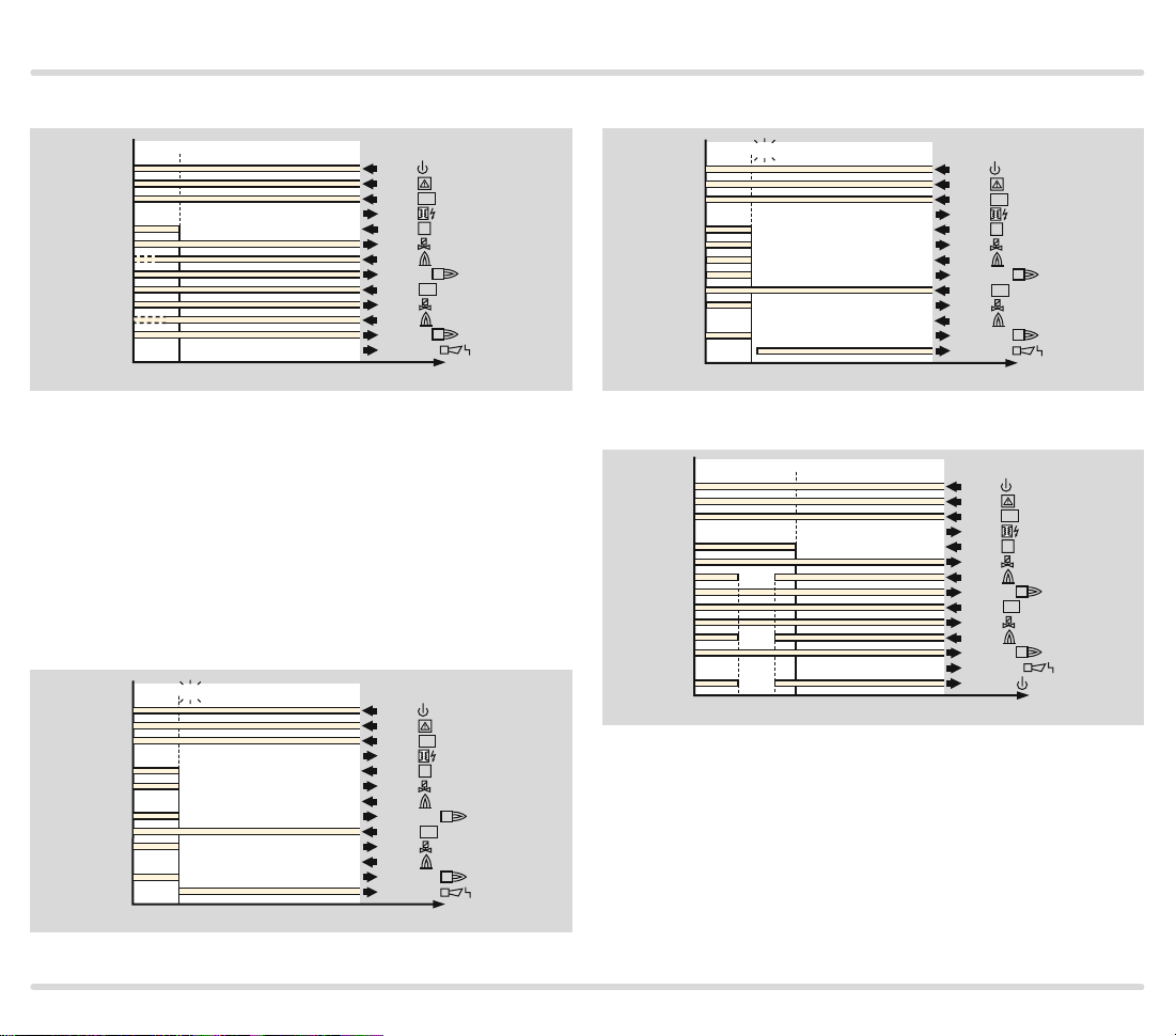
4.2.5 High temperature operation with PFU..D
Parameter 33
Operation of firing systems at temperatures above
750°C. The PFU features a safety-relevant DI input
(Digital Input). This input supports the “High temperature operation” function. If firing systems are operated
above 750°C, the system is considered to be a high
temperature equipment (see EN 7462). Flame control
must be in operation until the furnace wall temperature
has exceeded 750°C. Note the requirements of the
Standards!
Flame control can be dispensed with during high temperature operation to improve the system availability.
This means that no incorrect flame signals, e.g. signals
from a UV sensor which are interpreted as extraneous
signals due to reflection of UV radiation, may lead to
faults.
When the DI input is activated, the burner control unit
reverts to High temperature mode. This means: the PFU
operates without evaluation of the flame signal. The
safety function of the device-internal flame control system is placed out of operation.
In High temperature mode, the gas valves are opened
without flame control.
The precondition for high temperature operation is that
an external flame safeguard ensures the presence of
the flame in fail-safe manner indirectly via the temperature. For this purpose, we recommend a safety tem-
perature monitor with twin thermocouple (DIN 3440).
Sensor discontinuity, sensor short-circuit, failure of a
component or mains failure must set the installation to
a safe state.
The voltage may be applied to the DI input (terminal
22a) so as to activate High temperature mode only
when the temperature at the furnace wall has exceeded
750°C. The PFU starts the burner as usual, without
monitoring the presence of the flame.
0402 03
06 07 0800
t
t
Z
t
SA1
FS1
t
SA2tFS2
88
30a
26e
10e
28c
22a
16c
26a
2c–4c
14a
18e
18a
6a–6e
2e–4e
ϑ1
DI
V1
1
1
ϑ2
V2
2
2
t
If the temperature in the furnace chamber drops below
750°C, the DI input must be disconnected from the
electrical power supply and the furnace must be operated with the internal flame control system.
PFU 780 · Edition 02.12l 21
Page 22

Parameters
▼
The PFU then responds, depending on setting:
Parameter 33 = 1
0402 0301
06 07 0808
FA
t
W
t
t
t
SA1
FS1
Z
t
SA2tFS2
88
30a
26e
10e
28c
22a
16c
26a
2c–4c
14a
18e
18a
6a–6e
2e–4e
2a–4a
ϑ1
DI
V1
1
1
ϑ2
V2
2
2
t
If the flame fails during high temperature operation, the
ready contact opens for the duration of the flame failure (FA).
When High temperature mode is ended, the PFU
switches off the burner and restarts with flame simulation check (recommended in the case of UV control
with UVS).
Parameter 33 = 2
0402 0301
06 07 0808
t
t
t
t
W
Z
SA1
FS1
t
SA2tFS2
88
30a
26e
10e
28c
22a
16c
26a
2c–4c
14a
18e
18a
6a–6e
2e–4e
2a–4a
ϑ1
DI
V1
1
1
ϑ2
V2
2
2
t
When High temperature mode is ended, the PFU
switches off the burner and restarts with flame simulation check (recommended in the case of UV control
with UVS).
PFU 780 · Edition 02.12l 22
Page 23
Parameters
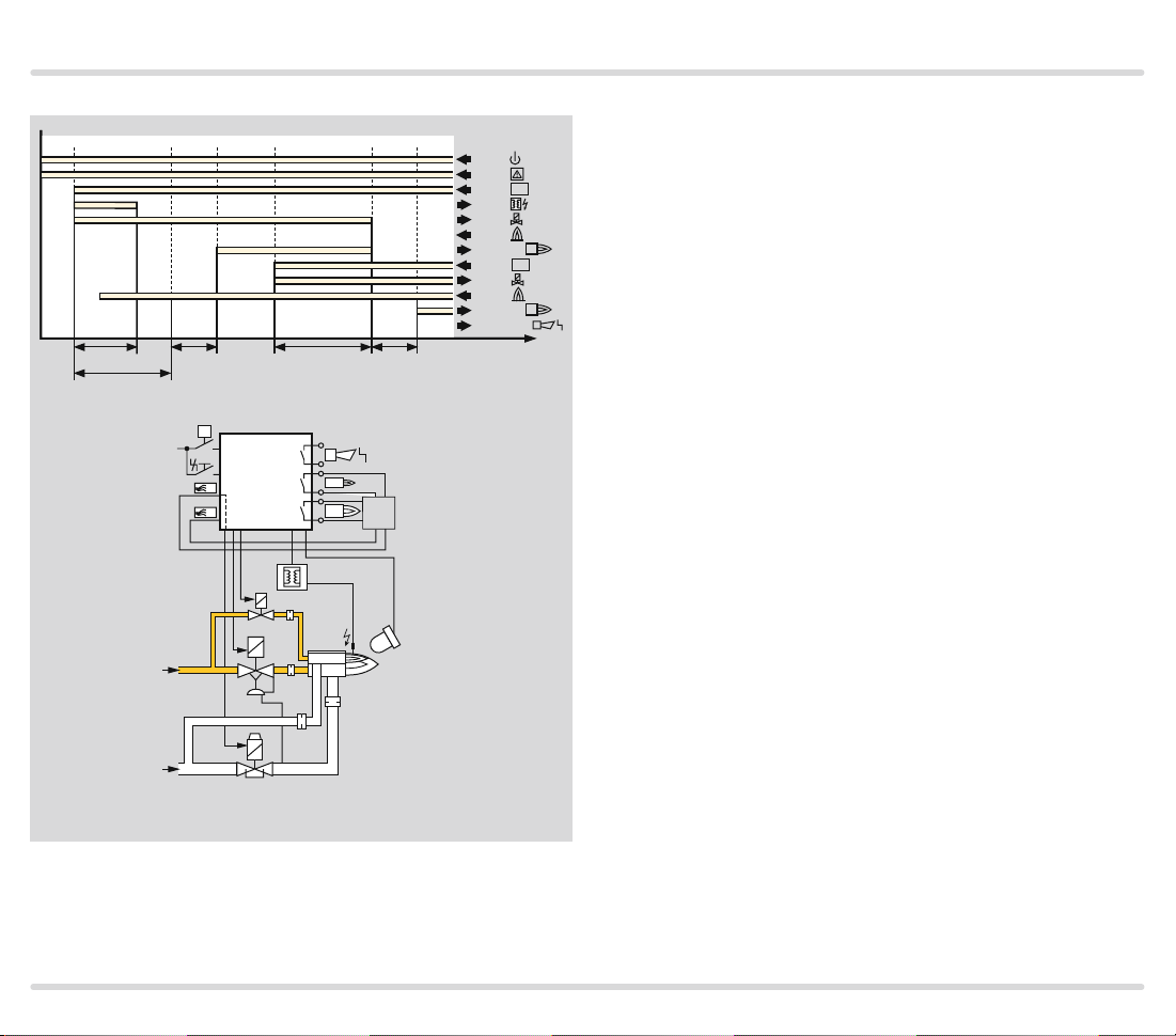
Parameter 33 = 3
08
08
88
30a
26e
10e
28c
22a
16c
26a
2c–4c
14a
18e
18a
6a–6e
2e–4e
ϑ1
DI
V1
1
1
ϑ2
V2
2
2
t
When High temperature mode is ended, the burner remains in operation and the PFU performs flame control
again (recommended in the case of ionisation control or
UV control with UVD).
If no flame signal is present when High temperature
mode is ended, the burner control unit performs a fault
lock-out, regardless of parameter 33.
Fault, pilot burner
04 04
88
30a
26e
10e
28c
22a
16c
26a
2c–4c
14a
18e
18a
6a–6e
2e–4e
ϑ1
DI
V1
1
1
ϑ2
V2
2
2
t
Fault, main burner
08
08
88
30a
26e
10e
28c
22a
16c
26a
2c–4c
14a
18e
18a
6a–6e
2e–4e
ϑ1
DI
V1
1
1
ϑ2
V2
2
2
t
Parameter 33 = 4
08
08
88
30a
26e
10e
28c
22a
16c
26a
2c–4c
14a
18e
18a
6a–6e
2e–4e
2a–4a
ϑ1
DI
V1
1
1
ϑ2
V2
2
2
t
If the flame fails during high temperature operation, the
ready contact is opened for the duration of the flame
failure.
When High temperature mode is ended, the burner remains in operation and the PFU performs flame control
again (recommended in the case of ionisation control or
UV control with UVD).
PFU 780 · Edition 02.12l 23
Page 24

Parameters
4.2.6 UVS check
Parameter 35
An automatic restart of the burner control unit can be
activated every 24 hours via this parameter. The time
starts each time the start-up signal (ϑ) is applied.
Parameter 35 = 0: Unlimited burner operation.
Parameter 35 = 1: An automatic restart is activated
once every 24 hours.
It must be ensured in this case that the program sequence started matches the application. This parameter may be set in this way only if the burner can restart
as intended in all operating phases.
PFU 780 · Edition 02.12l 24
Page 25

Parameters
t
4.3 Pilot and main burner monitoring
Burner control unit PFU 780 for pilot and main burner
combination of unlimited capacity.
Pilot burner: single-stage-controlled.
Main burner: modulating or stage-controlled.
The burner control unit PFU 780 has separate start-up
signal inputs for the pilot burner (terminal 10e) and the
main burner (terminal 14a). The burner control unit coordinates the program run (the interplay) of both burners. If required, the main burner can be started once the
pilot burner has reached its operating position. Benefit:
The time for starting up the main burner can be reduced
as low as its safety time. By using two flame amplifiers,
the pilot and main burners can be monitored separately.
The PFU 780 can also be used on indirectly ignited sur-
face burners with end point monitoring.
Three different operating modes are possible:
Permanent pilot burner
88 02–04 06–08 04 06–08 04
ϑ1
1
ϑ2
2
For applications which require a high system availabil-
ity or where a continuously burning flame is necessary.
The pilot burner is ignited once and remains constantly
in operation. The main burner is controlled separately.
Intermittent pilot burner
88 02–04 06–08 00 02–04 06–08 00
ϑ
1
2
t
Pilot and main burners are controlled with one start-
up signal (terminals 10e and 14a in parallel). The main
burner starts automatically after the operating signal
from the pilot burner has been detected. Operation is
terminated simultaneously for both burners.
PFU 780 · Edition 02.12l 25
Page 26

Parameters
Interrupted pilot burner
88 02–04 06–08 02–04 06–08
ϑ1
1
ϑ2
2
t
The pilot burner is switched off during the main burner
safety time t
no distinction can be made between the flame signals
of the pilot and main burners (e.g. if both burners can
be monitored with a single UV sensor). If the start-up
signal for the pilot burner is applied continually, the
pilot burner restarts immediately after the main burner
has been switched off.
. This type of flame control is required if
SA2
PFU 780 · Edition 02.12l 26
Page 27

Parameters
4.3.1 Permanent pilot burner Parameter 16 = 1
04 06 07 08 02 03 00
t
Z
t
SA1
t
FS1
ϑ
L1
PFU 780
A
P
t
SA2
TZI
VBY
VAG
1
t
1
SPS
2
PLC
CPE
2
FS2
88
30a
26e
10e
28c
16c
26a
2c–4c
14a
18e
18a
6a–6e
2e–4e
ϑ1
V1
1
1
ϑ2
V2
2
2
t
Operating mode: Permanent pilot burner
In the “Permanent pilot burner” operating mode, the pilot burner remains in operation until its start-up signal
drops.
If this parameter is activated (P16 = 1), both flames are
controlled independently in the case of pilot and main
burner monitoring.
Operating mode: Intermittent pilot burner
Start-up as in the illustration “Permanent pilot burner”
with the difference being that the start-up signal for pilot and main burners is applied synchronously and that
immediately after the flame proving period t
main burner is started.
FS1
, the
VR..R
PFU 780 · Edition 02.12l 27
Page 28
Parameters
4.3.2 Interrupted pilot burner Parameter 16 = 0
04 06 07 08 02 03 00
t
Z
t
SA1
t
FS1
ϑ
L1
PFU 780
A
P
VAS
t
TZI
SA2
t
FS2
1
SPS
2
PLC
CPE
88
30a
26e
10e
28c
16c
26a
2c–4c
14a
18e
18a
6a–6e
2e–4e
ϑ1
V1
1
1
ϑ2
V2
2
2
t
Operating mode: Interrupted pilot burner
If parameter 16 = 0, the pilot burner is switched off once
the safety time t
flame signal can be connected to terminals 18a or 26a.
The pilot burner is switched off after the main burner
safety time t
SA2
has elapsed. In this setting, the
SA2
has elapsed.
VAG
VR..R
UV
1
2
PFU 780 · Edition 02.12l 28
Page 29

Parameters
4.4 Behaviour in start-up position/standby
4.4.1 Flame simulation check in start-up position/ standby
Parameter 15
This defines the instant for the flame simulation check.
88
00
t
LV
If the PFU notices an extraneous signal during the
flame simulation check, it starts the flame simulation
delay time tLV (25 s). If the extraneous signal is discontinued during this period, the burner can start up. Otherwise, a fault lock-out occurs. 1 blinks on the display
if an extraneous signal is detected by the pilot burner
and 5 blinks if an extraneous signal is detected by the
main burner.
Parameter 15 = 0: The flame simulation check is conducted after applying the start-up signal (ϑ) during the
waiting time t
.
W
Parameter 15 = 1: The flame simulation check is conducted provided no start-up signal (ϑ) is applied (during
the so-called start-up position/standby). This allows fast
start-up of the burner since there is no waiting time t
01
30a
26e
10e
28c
26a
16c
18e
2c–4c
2e–4e
ϑ1
V1
V2
1
t
.
W
The burner must have been switched off for at least 4 s
before start-up in order for the flame simulation check
to be conducted correctly.
Flame simulation check depending on parameter 16
(Pilot burner operating mode):
Parameter 15 = 1, Parameter 16 = 1
88 00 02 06
ϑ1
V1
ϑ2
V2
t
Parameter 15 = 0, Parameter 16 = 1
02
t
W1
06
t
W2
88 00 01 05
ϑ1
ϑ2
V1
V2
t
Parameter 15 = 1, Parameter 16 = 0
88 00 02 06
ϑ1
V1
ϑ2
V2
t
Parameter 15 = 0, Parameter 16 = 0
02
t
W1
06
t
W2
88 00 01 05
ϑ1
ϑ2
V1
V2
t
PFU 780 · Edition 02.12l 29
Page 30
Parameters
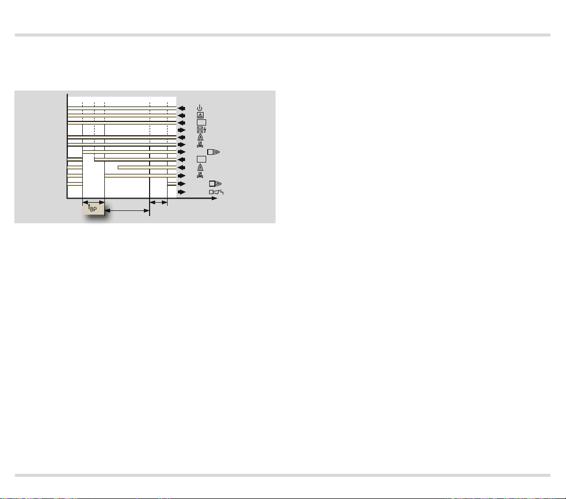
4.4.2 Minimum burner pause time tBP
Parameter 21
Programmable time between 0 and 250 s.
05 04
t
BP
t
SA2
t
FS2
88 08 06 07 08
1
5
ϑ
1
4
7
1
9
V1
12
16-17
ϑ
2
21
2
9
14 V2
28-29
18-19
1
2
t
An immediate restart of the main burner after a normal shut-down, a start-up attempt, restart, cooling
or purging is prevented by the pause time. The pause
time starts when the air valve is switched off. If a startup signal (ϑ2) is applied before expiry of this time, the
start-up is delayed until the end of the pause time.
After the pause time, the burner is started if the startup signal (ϑ) is applied.
The minimum burner pause time t
serves to adapt the
BP
program sequence to the requirements of the application.
The time should be set such that the system can be
moved to ignition position, i.e. butterfly valves can be
closed and, possibly, gas can be flared off, before a restart occurs.
See examples of application Stage-controlled main
burner with alternating pilot burner and Stage-controlled main burner with permanent pilot burner.
The pause time has an effect on the behaviour of the
main burner only. Background: The pilot burner is only
used in single-stage operation.
PFU 780 · Edition 02.12l 30
Page 31

Parameters
4.5 Behaviour during start-up
4.5.1 Safety time on start-up tSA
Pilot burner
Parameter 22
04 02 03 00
t
Z
t
SA1
Safety time on start-up t
t
FS
for the pilot burner.
SA1
88
30a
26e
10e
28c
26a
16c
18e
2c–4c
2e–4e
Main burner
Parameter 24
04 06 07 08 02 03 00
ϑ1
1
V1
V2
1
t
Safety time on start-up t
t
Z
t
SA1
t
FS1
t
SA2
for the main burner.
SA2
t
FS2
88
30a
26e
10e
28c
16c
26a
2c–4c
14a
18e
18a
6a–6e
2e–4e
ϑ1
V1
1
1
ϑ2
V2
2
2
t
PFU 780 · Edition 02.12l 31
Page 32

Parameters
4.5.2 Flame proving period tFS
Pilot burner
Parameter 23
t
Z
t
SA1
t
FS
Main burner
Parameter 25
04 06 07 08 02 03 00
t
Z
t
SA1
t
FS1
t
SA2
4.5.3 Minimum combustion time t
B
Parameter 20
04 06 07
88
04 02 03 00
30a
26e
ϑ1
10e
28c
1
26a
16c
V1
18e
V2
1
2c–4c
2e–4e
t
t
B
88
30a
26e
10e
16c
26a
2c–4c
14a
18e
18a
6a–6e
2e–4e
ϑ1
V1
1
1
ϑ2
V2
2
2
t
Programmable time to maximum 25 s during which the
main burner remains in operation. In the case of brief
activation of the start-up signal input (ϑ2) (e.g. with a
pulse), the combustion time tB is started, and the main
t
FS2
88
30a
26e
10e
28c
16c
26a
2c–4c
14a
18e
18a
6a–6e
2e–4e
ϑ1
V1
1
ϑ2
V2
2
t
burner remains in operation for at least this period.
1
2
Programmable time between 0 and 25 s.
This time elapses before the PFU starts the next pro-
gram step so as to give the flame time to stabilise.
PFU 780 · Edition 02.12l 32
Page 33

Parameters
4.5.4 Burner start-up attempts
Pilot burner
Parameter 10
This indicates the number of possible start-up attempts
of the burner.
In accordance with EN 7462, three start-ups are permitted in specific cases in the event of flame failure
during start-up, if the safety of the installation is not
impaired. Note the requirements of the Standards!
If no flame is detected during start-up, either a fault
lock-out is performed or further start-up attempts in
accordance with EN 7462 occur.
Pursuant to NFPA 86, only one start-up attempt is permitted in the event of flame failure during start-up. For
units approved by FM Approval (see type label), it is
only possible to select one start-up attempt.
1 start-up attempt
Parameter 10 = 1
02 00
t
Z
02
t
SA
88
30a
26e
10e
28c
26a
16c
18e
2c–4c
2e–4e
ϑ1
V1
V2
t
If no flame forms during start-up, a fault lock-out is
performed after expiry of time tSA. The display blinks
and shows the cause of the fault.
2 or 3 start-up attempts
Parameter 10 = 2, 3
02 00
t
Z
t
SA1
t
Z
88
30a
26e
ϑ1
10e
28c
26a
V1
16c
V2
18e
1
2c–4c
2e–4e
t
t
SA1
If several start-up attempts are set and if the PFU detects a flame failure during start-up, it closes valve V1
after the safety time t
has expired and attempts to
SA1
start up again. After the last programmed start-up attempt has been completed, the burner control unit conducts a fault lock-out. The display blinks and shows the
cause of the fault.
PFU 780 · Edition 02.12l 33
Page 34

Parameters
Main burner
Parameter 11
This indicates the number of possible start-up attempts
of the main burner.
In accordance with EN 7462, three start-ups are permitted in specific cases in the event of flame failure
during start-up, if the safety of the installation is not
impaired. Note the requirements of the Standards! If no
flame is detected during start-up, either a fault lock-out
is performed or further start-up attempts in accordance with EN 7462 occur.
Pursuant to NFPA 86, only one start-up attempt is permitted in the event of flame failure during start-up. For
units approved by FM Approval (see type label), it is
only possible to select one start-up attempt.
1 start-up attempt
Parameter 11 = 1
04 06 02 03 00
t
Z
t
SA1
t
FS1
t
SA2
06
88
30a
26e
10e
28c
16c
26a
2c–4c
14a
18e
18a
6a–6e
2e–4e
ϑ1
V1
1
1
ϑ2
V2
2
2
t
If no flame forms during the start-up of the main burner,
a fault lock-out is performed after expiry of time t
SA2
.
The display blinks and shows the cause of the fault.
2 or 3 start-up attempts
Parameter 11 = 2, 3
04 06 02 03 00
t
Z
t
SA1
t
FS1
t
SA2
05
t
06
t
W
SA2
05
t
06
06
t
W
SA2
88
30a
26e
10e
28c
16c
26a
2c–4c
14a
18e
18a
6a–6e
2e–4e
ϑ1
V1
1
1
ϑ2
V2
2
2
t
If several start-up attempts are set and if the PFU does
not detect a flame signal during start-up, it closes valve
V2 after the safety time t
has expired and attempts
SA2
to start up again. After the last programmed start-up
attempt has been completed, the burner control unit
conducts a fault lock-out. The display blinks and shows
the cause of the fault.
PFU 780 · Edition 02.12l 34
Page 35

Parameters
▼
4.6 Behaviour during operation
4.6.1
Safety time during operation tSB for pilot and main
burners
Parameter 14
This indicates the safety time during operation tSB
for valves V1 and V2. The default in accordance with
EN 298 is 1 s. The PFU has also the available option of
a safety time during operation tSB of 2 s. Prolonging the
time increases the installation availability in the case
of brief-duration signal fades (e.g. fades of the flame
signal). In accordance with EN 7462, the safety time
of the installation during operation (including closing
time of the valves) may not exceed 3 seconds (note the
requirements of the Standards).
4.6.2 Fault lock-out or restart, pilot burner
Parameter 12
This parameter determines whether the PFU starts a
one-off restart or performs an immediate fault lock-out
for the burner after an installation fault such as a flame
failure or failure of air flow (see also Project planning
information).
Immediate fault lock-out following flame failure
Parameter 12 = 0:
Pilot burner fault lock-out.
04
04
t
SB
88
30a
26e
10e
28c
26a
16c
18e
2c–4c
2e–4e
ϑ1
1
V1
V2
1
t
After a fault lock-out, the burner control unit can be
reset, either with the button on the front panel or using
an external button. Several burner control units can be
reset in parallel using the external button.
The PFU cannot be reset by mains failure. The fault
signalling contact does, however, open as soon as the
mains voltage fails.
See also parameter 32, Behaviour of the air valve in the
event of a fault lock-out.
PFU 780 · Edition 02.12l 35
Page 36

Parameters
Restart following flame failure
Parameter 12 = 1:
Restart following flame failure.
1x
88
04 04 03 01
30a
26e
ϑ1
10e
28c
1
26a
16c
>2 s
t
t
SB
t
Z
t
t
W
SA1
FS1
If the PFU detects a flame failure after a minimum operating time of 2 s, the valves are closed and the operation signalling contact is opened within time tSB.
The burner control unit now attempts to restart the
burner once. If the burner does not function, a fault
lock-out occurs. The display blinks and shows the
cause of the fault.
In accordance with EN 7462, a restart may be conducted only if the safety of the installation is not impaired. Restart is recommended for burners which occasionally display unstable behaviour during operation.
The precondition for a restart is that activation of the
restart allows the burner to restart as intended (in all
operating phases). In this case, it must be ensured that
the program sequence started by the PFU matches the
application.
2c–4c
2e–4e
V1
1
t
PFU 780 · Edition 02.12l 36
Page 37

Parameters
S
▼
4.6.3 Fault lock-out or restart, main burner
This parameter determines whether the PFU starts a
one-off restart or performs an immediate fault lock-out
for the main burner after a flame failure (see also Project planning information).
Immediate fault lock-out following flame failure
Parameter 13 = 0:
Main burner fault lock-out
08
08
t
B
88
30a
26e
10e
28c
16c
26a
2c–4c
14a
18e
18a
6a–6e
2e–4e
ϑ1
V1
1
1
ϑ2
V2
2
2
t
After a flame failure, the burner control unit performs
a fault lock-out within the safety time during operation
tSB. This involves disconnecting the power from the gas
valves and the ignition transformer. The fault signalling
contact closes, the display blinks and shows the current
program status (see table “Program status and fault
messages”).
After a fault lock-out, the burner control unit can be
reset, either with the button on the front panel or using
an external button. Several burner control units can be
reset in parallel using the external button.
The PFU cannot be reset by mains failure. The fault
signalling contact does, however, open as soon as the
mains voltage fails.
See also “Behaviour of the air valve in the event of a
fault lock-out”.
PFU 780 · Edition 02.12l 37
Page 38

Parameters
Restart following flame failure
Parameter 13 = 1:
Restart following flame failure.
1x
08
>2 s
06
05
t
SB
t
t
W2
SA2
07
08
t
FS2
88
30a
26e
10e
28c
16c
26a
2c–4c
14a
18e
18a
6a–6e
2e–4e
ϑ1
V1
1
1
ϑ2
V2
2
2
t
If the PFU detects a flame failure after a minimum operating time of 2 s, valve V2 is closed and the operation
signalling contact is opened within time tSB.
The burner control unit now attempts to restart the
main burner once. If the burner does not function, a
fault lock-out occurs. The display blinks and shows the
cause of the fault.
In accordance with EN 7462, a restart may be conducted only if the safety of the installation is not impaired. Restart is recommended for burners which occasionally display unstable behaviour during operation.
The precondition for a restart is that activation of the
restart allows the burner to restart as intended (in all
operating phases). In this case, it must be ensured that
the program sequence started by the PFU matches the
application.
PFU 780 · Edition 02.12l 38
Page 39

Parameters
4.7 Air valve control PFU..L
Parameter 30, Behaviour of the air valve during operation
Parameter 31, Behaviour of the air valve during start-up
Parameter 32, Behaviour of the air valve in the event of
a fault lock-out
The PFU..L features an adjustable air valve control. The
display shows that purging is currently being carried
out with
tivated for cooling or heating.
The PFU..L supports the following functions:
– Purge
– Cooling in start-up position/standby
– Switching of the burner between low and high burner
output during operation via the air valve
– To start up the burner as intended, external activation
of the air valve can be blocked during start-up (prevents synchronisation problems between the PFU
and the central control system)
– Controlling the air valve so that it
– opens with valve V2,
– opens once the main burner has reached its operat-
ing position
– Low fire over run time t
P 0
. A indicates that the air valve is being ac-
after a normal shut-down
KN
4.7. 1 Purge
Parameter 42 = 0: The air valve is closed when voltage is
applied to terminal 30e.
Parameter 42 = 1: The air valve is opened when voltage
is applied to terminal 30e.
In the case of multiple burner applications, burners with
mechanical combustion air supply are used. The air for
combustion and pre-purge is supplied by a central fan
controlled by a separate logic. This logic determines the
purging time.
The PFU..L supports centrally-controlled pre-purge or
post-purge. The PFU..L is informed that purging is currently being performed by input 30e. It then opens the
air valve, regardless of the status of the other inputs
(purging has priority). The display indicates
PFU 780..K2: For purging, the safety interlock (limits)
must activate input 26e and input 30e of the PFU.
4.7. 2 Cooling in start-up position/standby
The air valve can be activated externally via input 10a
for cooling in the start-up position. During activation of
the air valve the display shows
ing is currently being carried out.
4.7.3 Burner start
Parameters 30 and 31 determine the behaviour of the
air valve during burner start.
A 0
, indicating that cool-
P 0
.
PFU 780 · Edition 02.12l 39
Page 40

Parameters
PFU 780
A
P
L1
1
2
SPS
PLC
CPE
ϑ
VR..R
VAG
TZI
2
1
UV
VAS
4.7. 4
Air valve opens in the c ase of exter nal activation ( not
during start-up)
00 A0 00
A0
03
02
t
t
Z
t
SA1
06
04
t
t
FS1
SA2
FS2
88
A807
30a
26e
10e
28c
16c
26a
2c–4c
14a
18e
18a
6a–6e
10a
22e
2e–4e
Parameter 30 = 0:
The air valve opens if it is activated externally by input 30e.
Parameter 31 = 0:
The air valve remains closed during start-up
ϑ1
V1
1
1
ϑ2
V2
2
2
A
t
even if it is activated externally.
These settings are required on burners on which the
gas/air ratio is controlled via a pneumatic link and
which also need to be started at low fire, e.g. on twostage-controlled burners. In this case, activation of the
air valve during burner start via input 10a must be prevented.
External control allows switchover between low fire and
high fire during operation.
The air valve can be activated externally via input 10a
for cooling the burner in the start-up position/standby.
PFU 780 · Edition 02.12l 40
Page 41

Parameters
SA1
4.7. 5 Air valve opens in the case of external activation (even during start-up)
00 A0 00
A0
A2
L1
A4
FS1
PFU 780..L
VAS 1
VAG
A6
t
SA2
TZI
t
FS2
1
2
1
2
A3
t
t
Z
t
ϑ
A
P
88
A8 A7
30a
26e
ϑ1
10e
28c
V1
16c
1
26a
1
2c–4c
ϑ2
14a
V2
18e
2
18a
2
6a–6e
A
10a
22e
2e–4e
t
UV
Parameter 30 = 0:
The air valve opens if it is activated externally via input 10a.
Parameter 31 = 1:
The air valve can be activated even during start-up.
These settings may be selected only if the burner can
start with full air capacity.
The air valve can be activated externally via input 10a
for cooling the burner in the start-up position/standby.
VAS
PFU 780 · Edition 02.12l 41
Page 42

Parameters
SA1
4.7. 6 Air valve opens with valve V2
00 A0
00
02
L1
03
t
t
Z
t
ϑ
A
P
A6
04
t
FS1
PFU 780..L
SA2
TZI
VBY
VAG
1
t
FS2
1
2
2
SPS
PLC
CPE
Parameter 30 = 2:
88
A8 A7
30a
26e
ϑ1
10e
28c
V1
16c
1
26a
1
2c–4c
ϑ2
14a
V2
18e
2
18a
2
6a–6e
A
10a
22e
2e–4e
t
The air valve opens simultaneously with valve V2.
Application:
Single-stage-controlled main burner is switched ON/
OFF via the ϑ input.
The air valve can be activated externally via input 10a
for cooling the burner in the start-up position/standby.
VR..R
PFU 780 · Edition 02.12l 42
Page 43
Parameters
4.7.7 Air valve opens with operating signal
04
06
t
SA
ϑ
L1
A
P
t
FS
PFU 780..L
TZI
VBY
VAG
1
88
A8 07
30a
26e
ϑ1
10e
28c
V1
16c
1
26a
1
2c–4c
ϑ2
14a
V2
18e
2
18a
2
6a–6e
A
10a
22e
2e–4e
t
1
SPS
2
PLC
CPE
2
Parameter 30 = 3:
The air valve opens simultaneously with the operating
signal.
Application:
Two-stage-controlled main burner is switched ON/OFF
via the ϑ input.
The air valve can be activated externally via input 10a
for cooling the burner in the start-up position/standby.
VR..R
PFU 780 · Edition 02.12l 43
Page 44

Parameters
KN
PFU 780..L
A
L1
1
SPS
ϑ
4.7. 8
Low fire over run time tKN after a nor mal shut-down
A8
t
P
VG..N
VAS 1
GIK..B
VR..R
88
00
30a
26e
ϑ1
10e
28c
16c
26a
2c–4c
ϑ2
14a
18e
18a
6a–6e
22e
2e–4e
2
PLC
CPE
TZI
1
2
Parameter 36
Settings: 0; 3; 5; 10; 15; 25 or 60 (low fire over run time
in seconds)
This parameter is applicable to systems with a pneu-
V1
1
1
V2
2
2
matic link between gas and air and On/Off control.
Parameter 36 = 0 (low fire over run time t
KN
= 0 s):
Without low fire over run, the gas side is closed immediately owing to the quick-closing gas valve in the case
of On/Off control. The air side closes more slowly. The
t
air flowing in during the closing time increases the O2
content in the combustion chamber.
Parameter 36 = 3; 5; 10; 15; 25 or 60 (low fire over run
time t
= 3, 5, 10, 15, 25 or 60 s):
KN
The air valve closes slowly after the activation signal
has been switched off. The gas valve remains open for
tKN. This means that the burner, after deactivation of
the main burner start-up signal (ϑ2), is initially adjusted
down to low fire and then switched off completely.
Using the low fire over run function reduces the O
con-
2
tent in the furnace atmosphere.
Flame control is still operational. Can be used only in
the case of pneumatic link and On/Off control. It must
be ensured that no excess gas occurs.
The low fire over run time has an effect on the behaviour
of the main burner only.
Background: The pilot burner is only used in single-
stage operation.
PFU 780 · Edition 02.12l 44
Page 45

Parameters
4.7. 9
Behaviour of the air valve in the event of a fault lock-
out
Parameter 32:
This determines whether the air valve can be activated
in the case of a fault lock-out.
Parameter 32 = 0:
The air valve is closed in the event of a fault. It cannot be
activated externally via terminal 10a.
Parameter 32 = 1:
The air valve can be activated externally via input 10a
even during a fault, e.g. for cooling.
PFU 780 · Edition 02.12l 45
Page 46

Parameters
4.8 Manual operation
For convenient setting of the burner or analysing faults.
The parameter display is not available in Manual mode.
Manual mode can be accessed only if the unit was not
in Fault state before switching off. The following times/
functions are not active in Manual mode: start-up attempts, restart, minimum combustion time and cycle
lock.
If the Reset /Information button is pressed for 2 s during switch-on, the PFU reverts to Manual mode. Two
dots blink on the display.
In this operating mode, the burner control unit operates
independently of the status of the inputs (apart from
the pre-purge input and the safety interlocks. These are
of higher priority and will be processed first).
Each time after the button is pressed again, the PFU
moves to the next section of the program sequence
and stops there. After approx. 3 s, the flame signal will
be displayed instead of the program parameter. Briefly
pressing the Reset/Information button (< 1 s) displays
the relevant Manual mode step. If there is flame simulation during the start-up, the flame signal is displayed
immediately.
On units with air valve control, the air valve can be
opened and closed repeatedly by pressing the button
during operation.
Manual mode can be terminated by switching off the
PFU (On/Off button).
4.8.1 Manual mode limited to 5 minutes
Parameter 34:
Parameter 34 determines when Manual mode is termi-
nated.
Parameter 34 = 0:
Manual mode is not limited in time. If this function has
been selected, operation of the furnace may be continued manually in the event of failure of the central control system.
Parameter 34 = 1:
Manual mode ends automatically five minutes after the
last time the button was pressed. The PFU then moves
abruptly back to start-up position/standby.
PFU 780 · Edition 02.12l 46
Page 47

Parameters
4.9 Password
Parameter 50:
(Four-digit) password saved to protect parameter
settings. To prevent unauthorised changes to parameter settings, a password is stored in parameter 50.
Changes to parameter settings can only be made once
this number has been entered. The password can be
changed using BCSoft.
Note the effect of parameter settings on the safe functioning of your system.
The password set at the factory can be found in the de-
livery note supplied.
PFU 780 · Edition 02.12l 47
Page 48

Selection
5 Selection
5.1 Calculating the safety time tSA
PFU 780 · Edition 02.12l 48
Page 49

Selection
PF U 780LT
5.2 Selection table
Type L T N D* U* K2*
PF U 780
* If “none”, this specifi cation is omitted.
= standard, = available
Order example
5.2.1 Type code
Code Description
L Air valve control
T
N
D* Digital input to interrupt fl ame control
U* Preparation for UV sensor for continuous operation UVD 1
K2* Compatible with PFU 798
* If “none”, this specifi cation is omitted.
220–240 V~, 15/+10 %, 50/60 Hz
110–120 V~, 15/+10 %, 50/60 Hz
Mains voltage
PFU 780 · Edition 02.12l 49
Page 50

Project planning information
6 Project planning information
6.1 Cable selection
Use mains cable suitable for the type of operation and
complying with local regulations. Do not route PFU
cables in the same cable duct as frequency converter
cables or cables emitting strong fields.
6.1.1 Ignition cable
Use unscreened high-voltage cable, see page 56
(Accessories). Cable length: max. 5 m, recommended
< 1 m. Screw the ignition cable securely into the ignition
transformer and run to the burner by the shortest possible route.
The longer the ignition cable, the lower the ignition
capacity. Only use radio interference suppressed electrode adapters (with 1 kΩ resistor) for ignition electrodes, see see page 56 (Accessories) . Do not lay
UV/ionisation cable and ignition cables together and
lay them as far apart as possible.
6.1.2 Ionisation cable
Use unscreened high-voltage cable, see page 56
(Accessories) . Cable length: max. 100 m. Avoid external electrical interference. Install as far as possible
from mains and ignition cables and interference from
electro-magnetic sources. If possible, do not lay in a
metal conduit. Several ionisation cables can be routed
together.
6.1.3 UVLeitung
Cable length: max. 100 m. Avoid external electrical
interference. Install as far as possible from mains and
ignition cables and interference from electro-magnetic
sources. If possible, do not lay in a metal conduit. Several UV cables can be routed together.
6.2 Ignition electrode
6.2.1 Electrode gap
Gap between electrode and burner earth:
2 mm ± 0.5 mm.
6.2.2 Star electrodes
We recommend using 7.5 kV ignition transformers on
burners with star electrodes.
PFU 780 · Edition 02.12l 50
Page 51

Project planning information
6.3 Minimum combustion time
Even if the start-up signal (ϑ) is applied only briefly, the
time set under parameter 20 elapses before the burner
control unit shuts down the burner or signals a fault. To
stabilise the burner operation, a minimum combustion
time can be set independently of the central control
system. If the start-up signal (ϑ) drops once the sec-
ond safety time t
remains in operation for at least time tB. The minimum
combustion time tB starts to elapse following controller
enable. If the start-up signal drops before the second
safety time t
SA2
reverts directly to standby and the burner is not ignited.
The signal inputs for the pilot /main burner start-up sig-
nal cannot be used for a safety shut-down because the
unit controls the valves until the minimum combustion
time has elapsed.
04 06 07
has started to elapse, the burner
SA2
, e.g. during pre-purge, the control unit
88
30a
26e
ϑ1
10e
V1
16c
1
26a
1
2c–4c
ϑ2
14a
18e
V2
2
18a
2
6a–6e
2e–4e
t
B
t
haviour of the main burner. The minimum combustion
time for the pilot burner is limited to the safety time on
star t-up (t
SA1
).
Background: The pilot burner is only used in single-
stage operation.
6.4 Safety interlocks (Limits)
The limiters in the safety interlock (linking of all the rel-
evant safety control and switching equipment for the
use of the application, e.g. safety temperature limiter,
minimum and maximum gas pressure, tightness control) must isolate terminal 26e from the voltage supply.
If the safety interlock is interrupted, this is indicated by
a blinking
If the safety interlocks fail, an immediate program abort
with switch-off of all outputs occurs (even during the
safety time). If the safety interlocks are operational
again or the unit is switched back on, the program run is
restarted in standby.
51
on the display.
In the case of pilot/main burner monitoring, the minimum combustion time only has an effect on the be-
PFU 780 · Edition 02.12l 51
Page 52

Project planning information
6.5 Emergency stop
6.5.1 In the event of fire or electric shock
If there is a risk of fire, electric shock or similar, inputs
L1, N and 26e (safety interlocks) of the PFU should be
disconnected from the electrical power supply–this
should be reflected in the wiring on site.
6.5.2 Via the safety interlocks (limits)
The safety interlock turns off the power to input 26e,
such as in the event of air deficiency or similar.
6.6 Reset
6.6.1 Parallel reset
Several burner control units can be reset in parallel using the external button. The PFU cannot be reset by
mains failure.
6.6.2 Permanent remote reset
Permanent remote reset gives rise to a malfunction. If a
remote reset signal is permanently applied to terminals
52
10c/12c,
Reset with a pulse < 1 s.
6.6.3 Automatic remote reset (PLC)
In the case of automatic remote reset (PLC), the reset
pulse duration should not exceed 1 second. Check
compliance with standards.
If a fault is acknowledged by remote reset too often, er-
10
ror
flashes on the display to indicate a fault.
(Too many remote resets) is displayed. The error
can only be acknowledged with the Reset /Information
button on the unit.
The burner malfunction must be remedied. The malfunction can not be remedied by changing the method
of activation.
6.6.4 Burner start
A furnace start may only be initiated, if it has been en-
sured using an appropriate procedure that there is no
combustible mixture in the combustion/processing
chamber, in the connected areas or in the exhaust gas
system (heat exchanger, dust collector). This can be
achieved by pre-purge, which occurs immediately be-
fore ignition or within the period specified in the operat-
ing instructions.
In the case of multiple burner applications, pre-purge is
not necessary after a normal burner shut-down.
Note the requirements of the Standards. For exceptions,
see Standards.
6.6.5 Restart and start-up attempts
The precondition for a restart/start-up attempt is that
activation of the restart allows the burner to restart as
intended (in all operating phases). In this case, it must
be ensured that the program sequence started by the
PFU matches the application.
Note the requirements of the Standards. For exceptions,
see Standards.
PFU 780 · Edition 02.12l 52
Page 53

Project planning information
6.7 Fault message
The fault signalling contact opens, as soon as the mains
voltage fails.
6.8 Protecting the pilot burner from overload
To protect the unit against overload by frequent cycling,
the maximum number of start-ups per minute is limited
for the PFU. Excessive cycling triggers a fault message
(blinking
depends on the safety time tSA:
tSA [s] Ignition transformer TZI Max. start-ups/min .
3 51 5/100 6
5 51 5/100 5
10 51 5/1 00 4
53
). The max. number of start-ups per minute
6.9 Installation
Installation position: any.
Installation in 19” module subracks only, see page
57 (Socket connectors)
Install in clean environment ensuring enclosure IP 54 or
higher, whereby no condensation is permitted.
Cable length between PFU and burner: max. 100 m.
6.10.1 UVS sensor wiring
Connect the UVS sensor directly to the PFU. Operating
the sensor with incorrect polarity or voltage can lead to
destruction of the sensor.
6.11 PFU switched off
The PFU cannot be activated when no mains voltage is
applied or when it is switched off. The fault signalling
contact is only closed when the unit is supplied with
voltage and switched on.
If the unit is switched off, an immediate program abort
with switch-off of all outputs occurs (even during the
safety time). When the unit is switched on, the program
run is restarted in standby.
6.10 Wiring
The PFU is suitable for hard wiring only. Do not reverse
phase and neutral conductor. Different phases of a
three-phase current system must not be installed at
the PFU. No voltage may be connected to the valve and
ignition outputs.
PFU 780 · Edition 02.12l 53
Page 54

Project planning information
6.12 Furnace control
Switch on the system to start up the furnace, then
release the burner start via the safety interlocks and
afterwards start the burner control so that the burner
control unit may monitor the burners as intended. To
shut down the furnace, first disconnect the burner
control unit from the temperature control (burner ON
signal), then disconnect the safety interlocks and finally
switch off the system.
6.13 Note on EC type-examination
Since EN 298 (1993) does not describe all functions of
the PFU, the operator is responsible for ensuring that all
parameters and functions are matched to the respective application.
6.14 Mains switch
The mains switch in the unit isolates the PFU on two
poles from the mains. It does not meet the requirements of EN 501561:2004 (5.2.2 Switch disconnectors) set out in chapter 5 for a device to disconnect the
power supply. Although the mains switch cannot be
used for disconnecting from the electrical power supply
in accordance with EN 50156, it does allow the burner
to be isolated functionally from the central control system. This function is required for manual operation and,
in the case of PROFIBUS units, to switch off the unit
without causing BUS errors. Disconnection for electrical maintenance work is to be implemented with an ex-
ternal switch per unit or group only, in accordance with
Standard “EN 50156”.
6.15 Changing parameters
In certain cases, it may be necessary to change the de-
fault settings. Using a separate software package and
a PC opto-adapter, it is possible to modify certain parameters on the PFU, such as the switch-off threshold
of the flame amplifier, the behaviour in the event of a
flame failure or if the pilot burner is to burn permanently
in the case of pilot and main burner monitoring.
The software package with PC opto-adapter, as well as
“Changed parameters” stickers, are available as acces-
sories – see section entitled page 56 (Accessories) .
The unit parameters set at the factory are specified in
the delivery note.
Document changed parameters in BCSoft using the
protocol function and enclose the protocol with the
plant documentation.
If a replacement is ordered for a PFU with changed parameters, refer to the protocol for details.
PFU 780 · Edition 02.12l 54
Page 55

Flame control
7 Flame control
7.1 With ionisation sensor
The PFU generates an alternating voltage (230 V AC)
between the sensing electrode and burner earth. The
flame rectifies this voltage. Only the DC signal (depending on the switch-off threshold for the pilot and main
burners) is recognised by the burner control unit as a
flame signal.
A flame cannot be simulated. Ignition and monitoring
with a single electrode is possible.
7. 2 With UV sensor
A UV tube inside the UV sensor detects the ultraviolet
light of a flame. It does not respond to sunlight, incandescent bulb light or infrared radiation emitted by hot
workpieces or red-hot furnace walls.
In the event of incident UV radiation the UV sensor rectifies the supplied alternating voltage. As with ionisation control, the burner control unit only detects this DC
signal.
When using UV sensors of Type UVS, the burner control
unit may be used for intermittent operation only. This
means that operation must be interrupted at least once
every 24 hours. This can be programmed using parameter 35.
For further information, see brochure UVS.
The burner control unit PFU..U is prepared for UV sensor
UVD 1. This enables continuous operation. For further
information, see Technical Information Bulletin UVD.
7.3 Via the temperature in high temperature equipment
High temperature equipment is defined as a thermo-
processing installation, in which the wall temperature of
the combustion chamber and/or the processing chamber exceeds 750°C. Burner control unit PFU..D features
a special “High temperature operation” function. During
heating up, standard monitoring methods (ionisation or
UV) must be used for flame control. When the working
temperature has exceeded 750°C, indirect flame control can be taken over by a central monitoring device.
When the DI input (terminal 22a) is activated, the burner control unit reverts to this operating mode.
Important: In “High temperature operation”, i.e. with
the DI input being activated, burner control unit PFU..D
does not evaluate the flame signal. The safety function
of the burner control unit’s flame control is deactivated
during this operating phase.
PFU 780 · Edition 02.12l 55
Page 56

Accessories
D-49018 Osnabrück, Germany
Achtung, geänderte Parameter!
Die Angaben auf dem Typenschild
gelten nicht mehr in vollem Umfang.
Aktuelle Parameter direkt auslesen.
Important, changed parameters!
The details on the type label are no
longer completely accurate. Read the
current parameters direct from the
unit.
Attention, paramètres modifiés !
Les informations figurant sur la plaque
signalétique ne sont plus valables
dans leur intégralité. Veuillez vous
référer directement aux paramètres
actualisés.
8 Accessories
8.1 High-voltage cable
FZLSi 1/7 up to 180°C, Order No.: 04250410.
FZLK 1/7 up to 80°C, Order No.: 04250409.
8.2 BCSoft
Opto-adapter including BCSoft CDROM,
Order No.: 74960437.
The current software can be downloaded from our In-
ternet site at http://www.docuthek.com. To do so, you
need to register in the DOCUTHEK.
8.3 Stickers for labelling
8.4 “Changed parameters” stickers
Affix on the connection diagram of the PFU following
changes to unit parameters set at the factory.
100 pcs, Order No.: 74921492.
For printing with laser printers, plotters or engraving
machines, 27 × 18 mm or 28 × 17.5 mm.
Colour: silver
PFU 780 · Edition 02.12l 56
Brenner 1
Zone 3
Page 57

Accessories
8.5 Radio interference suppressed electrode adapters
Plug cap, 4 mm, interference-suppressed,
Order No. 04115308.
Straight adapter, 6 mm, interference-suppressed,
Order No. 04115306.
8.6 Socket connectors
Type Order No.
Socket connector E, 48-pin solder tag connection 0 4120148
Socket connector E, 48-pin wire-wrap connection 04120158
8.7 Module subrack
Module subrack BGT S9U/1 for PFP 700, PFU 780
comprising:
module subrack, printed-circuit board with rear terminal
strip, function-tested, standard documentation, guide rails,
without partial front plates, screw terminals at the rear.
Slots 1–9 for PFU 760/780, slot 10 for PFP 700,
Order No. 84402281
Module subrack BGT SM8/1/1 for MPT 700,
PFU 780
comprising:
module subrack, printed-circuit board with rear terminal strip, function-tested, standard documentation,
guide rails, without partial front plates, screw terminals
at the rear, single-zone operation for MPT 700 operating modes 1–4, two-zone operation for MPT 700 operating modes 1–4, but max. 4 burners per zone.
Slot 1 for MPT 700, slots 2–9 for PFU 760/780, slot
10 for PFP 700
Order No. 84402282 (no illustration provided)
Module subrack BGT SA for PFA 700/PFU 760 and
PFA 710/PFU 780
consisting of:
odule subrack, printed-circuit board with rear terminal strip,
function-tested, standard documentation, guide rails, wit-
hout partial front plates, screw terminals at the rear, relays
and screw terminals for four free inputs and four free outputs, connection to PROFIBUS DP with DSub socket.
BGT SA9: slot 1 for PFA 700, slots 210 for PFU 760,
BGT SA8: slot 1 for PFA 710, slots 29 for PFU 780
Order no.
BGT SA9U/1 DP700: 84402291
BGT SA8U/1 DP710: 84402292 (no illustration provided)
PFU 780 · Edition 02.12l 57
Page 58
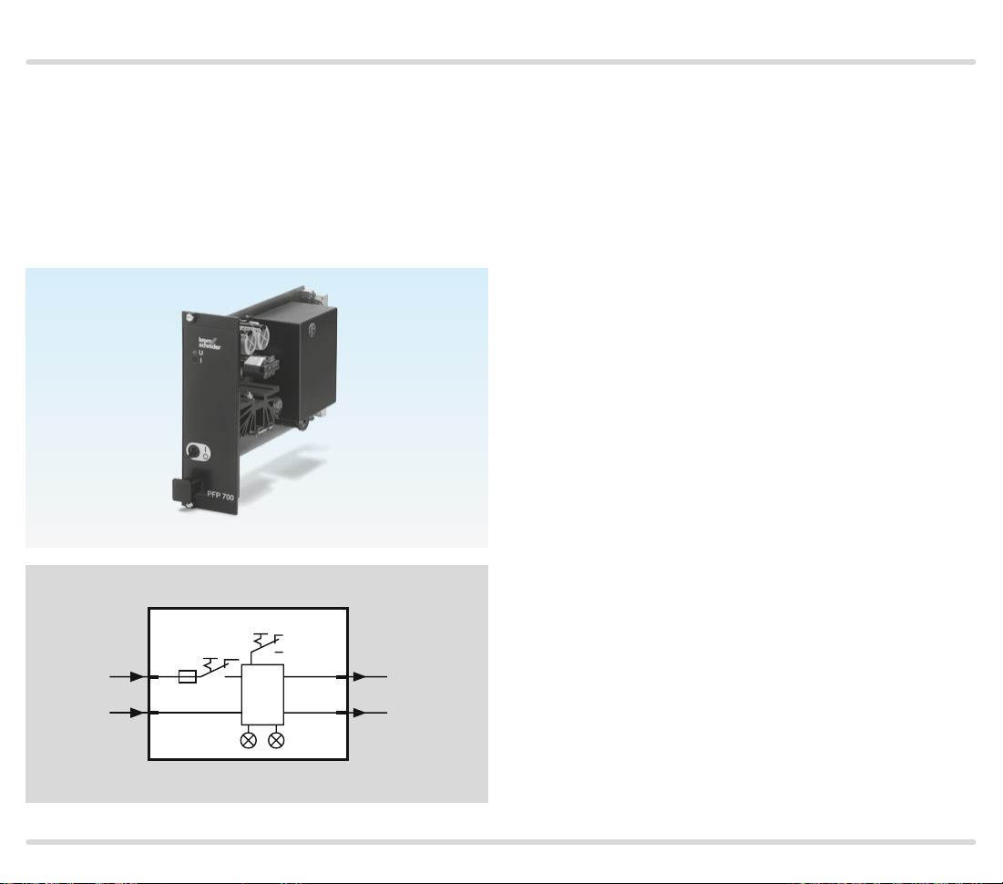
Accessories
8.8 Power supply PFP 700
For supplying the control inputs of burner control
unit PFU or for supplying the auxiliary voltage to relay
module PFR 704. Operating status display on the front
plate. PFP switches off in the event of an output overload. Output voltage 24 V, output rating 14 VA.
Order No. 84366510
L1
N
PFP 700
F1
30a
32c
S1
S0
O
I
UI
230 V
115 V
8ace
12ace
24 V=
600 mA
0 V
PFU 780 · Edition 02.12l 58
Page 59

Accessories
230 V~
115 V~
24 V=/~
0 V
230 V~
115 V~
24 V=/~
0 V
230 V~
115 V~
24 V=/~
0 V
230 V~
115 V~
24 V=/~
0 V
PFR 704
2e
2a
2c
1
4e
10e
10a
10c
2
12e
18e
18a
18c
3
20e
26e
26a
26c
4
28e
16a
16e
14a
14e
14c
16c
24a
24e
22a
22e
22c
24c
32a
32e
30a
30e
30c
32c
8.9 Relay module PFR 704
For contact multiplication, e.g. if several air valves are
activated via a single control signal for pre-purge, or
for heating/cooling switchover when using an MPT.
Switching status display on the front plate.
Input voltage:
110/120 V AC, 15/+10%, 50/60 Hz,
220/240 V AC, 15/+10%, 50/60 Hz,
24 V AC/DC, ± 10%.
Current per relay: 25 mA.
Contact rating of floating outputs: max. 2 A, 264 V (not
fused internally).
6a
6e
8a
8e
8c
max. 2 A, 264 Vmax. 2 A, 264 Vmax. 2 A, 264 Vmax. 2 A, 264 V
6c
Order No. 84373510
PFU 780 · Edition 02.12l 59
Page 60
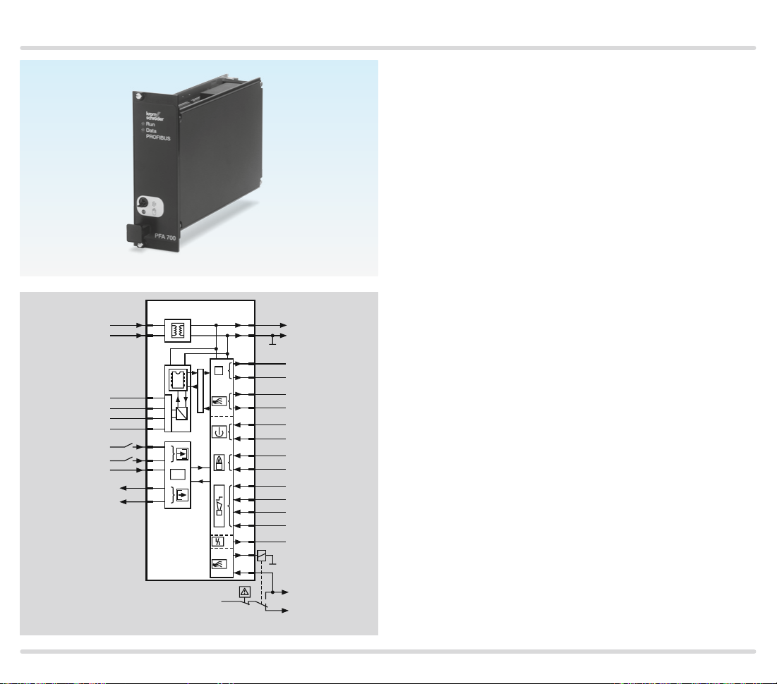
Accessories
8.10 Field bus interface PFA 700
For connection of up to nine automatic burner control
units PFU 760 to industrial communication networks
using PROFIBUSDP, in order to transfer measuring,
control and regulation signals as a bundle.
4 digital inputs: 24 V DC, ± 10%, < 10 mA ,
4 digital outputs: relay contact, max. 1 A, 264 V (not
fused internally).
Mains voltage: 110 – 240 V AC, 15/+10%, 50/60 Hz.
Further information can be found in Technical informa-
tion PFA.
L1
N
VP
RxD/TxD-P
RxD/TxD-N
DGND
24 V
…
24 V
0 V
24 V
24 V
PFA 700
32b
30a
8b
11b
12b
14b
18b
21b
22b
23b
…
26b
µC
PROFIBUS DP
1
…
4
I/O
1
…
4
15b
24 V=
16b
0 V
1c
1. PFU
10c
18c
10a
18a
19a
23a
20c
23c
19c
17b
24 V
30c
…
9c
9. PFU
1. PFU
…
9. PFU
1a
1. PFU
…
9a
9. PFU
1. PFU
…
9. PFU
1. PFU
…
5. PFU
6. PFU
…
9. PFU
PFU
30e
26e
PFU
ϑ
2
1
L1
PFU 780 · Edition 02.12l 60
Page 61

Accessories
L1
N
PE
1
mA
GND
2
mA
0
–
100%
GND
100% – 0
12–24 V
E2
E3
0 V
8.11 Impulse system MPT 700
With 11 outputs for activation of burner control units
PFU 780. The furnace atmosphere is circulated thanks
to intermittent operation, and thereby constant temperature distribution and shorter heating-up periods for
all gas-fired heat treatment furnaces are ensured.
Mains voltage: 95240 V AC, ± 10%, 50/60 Hz.
Power consumption: 10 VA.
Additional auxiliary voltage:
1224 V DC, ± 10%, max. 1.1 A.
Controller inputs: 2 x 0(4)20 mA with common earth,
floating, load impedance approx. 225 Ω.
MPT 700
30z
F1
30b
30d
28z
28b
28d
32z
32b
32d
20z
20b
20d
18z
18b
18d
E1
14z
14d
16z
14b
16b
8888
88
µC
2b
4b
10b
12b
2z
2d
4z
4d
6z
6d
8z
8d
10z
10d
12z
6b
8b
12–24 V
0 V
A1
A2
A3
A4
A5
A6
A7
A8
1
/
2
/
COM
Three-point step input: floating, 1224 V DC, load im-
pedance approx. 2.7 kΩ.
Digital inputs E1E3: with common earth, floating,
1224 V DC, load impedance approx. 2.7 kΩ.
Order No. 84395050
Further information can be found in brochure MPT.
PFU 780 · Edition 02.12l 61
Page 62
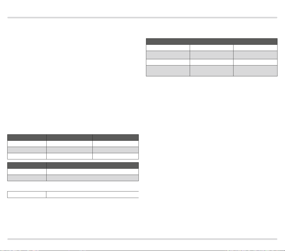
Technical data
▼
9 Technical data
Mains voltage:
220/240 V AC, 15/+10%, 50/60 Hz or
110/120 V AC, 15/+10%, 50/60 Hz,
for grounded and ungrounded mains.
Power consumption: < 8 VA.
Control inputs:
Input voltage/current:
Pilot burner, main burner, air valve, multi-flame control
and remote reset:
24 V DC, ± 10%, < 7 mA per input.
Input voltage for safety interlocks, digital input DI and
purge = mains voltage.
Input voltage of signal inputs:
Rated value 110/120 V AC 220/240 V AC
Signal “1” 80–132 V 160–264 V
Signal “0” 0–20 V 0–40 V
Frequenz 50/60 Hz 50/60 Hz
Rated value 24 V DC
Signal “1” 24 V, ±10 %
Signal “0” < 1 V
Output voltage for voltage-related outputs = mains
voltage.
Contact rating
Gas valve V1, V2 Max. 1 A resistive
Air valve Max. 1 A resistive
Ignition Max. 1 A resistive
Number of operating
cycles
Max. 1,000,000,
typically 400,000
Max. 1 A cos φ 0.3
Max. 1 A cos φ 0.3
Max. 1 A cos φ 0.3
Max. 250,000,
typically 100,000
Output current: max. 2 A per output, but total current
for valves and ignition transformer max. 2.5 A.
Operation and fault signalling contacts:
dry contact (floating), max. 1 A, 24 V, not fused internally.
Number of operating cycles:
Mains switch: 1000,
Reset/Information button: 1000.
Inherent current:
Signal “1” typ. 5 m A
PFU 780 · Edition 02.12l 62
Page 63

Technical data
Flame control:
Sensor voltage: approx. 230 V AC.
Sensor current: > 1 μA,
Length of sensor cable: max. 100 m.
Fuse in unit:
F1: 3.15 A, slow-acting, H pursuant to IEC 1272/5,
F2: 3.15 A, slow-acting, H pursuant to IEC 1272/5.
Ambient temperature:
20 to +60 °C (4 to +60.00 °C),
Climate: no condensation permitted.
Enclosure: IP 00 pursuant to IEC 529,
after installing in a 19” module subrack according to
the instructions, e.g. type BGT, the front corresponds to
IP 20.
Input/Output safety circuit:
All the inputs and outputs marked “
diagrams) may be used for safety tasks.
Weight: approx. 650 g (23 oz.).
” (see connection
PFU 780 · Edition 02.12l 63
Page 64

Technical data
9.1 Safety-specific characteristic values
In the case of ionization control, suitable
for Safet y Integrity Level
Diagnostic coverage DC 97. 9%
Type of subsystem Type B to EN 615082, 7.4.3.1.4
Mode of operation
Mean probability of dangerous failure
PFH
D
Mean time to dangerous failure MTTF
Safe failure fraction SFF 99.2%
The specified values apply for the combination with
ionization electrode (sensor) and PFU 780 (logic).
Relationship between the Performance Level (PL)
and the Safety Integrity Level (SIL)
PL SIL
a –
b 1
c 1
d 2
e 3
SIL 3
High demand mode pursuant to
EN 615084, 3.5.12
1.34 x 10⁸ l/h
MTTFd = 1 / PFH
d
D
Pursuant to EN ISO 138491:2006, Table 4, the PFU
can be used up to PL e.
Max. ser vice life under operating conditions:
20 years after date of production, plus max. 1/2 year in
storage prior to first use.
For a glossary of terms, see page 68 (Glossary).
PFU 780 · Edition 02.12l 64
Page 65

Technical data
3 HE =
133.4 (5.3“)
A
B
8 TE =
40.6 (1.6“)
D
9.2 Operating controls
A: 2-digit 7-segment display
B: Reset /Information button to reset the system after a
fault or to scan parameters on the display
C: Mains switch
C
F2
F1
D: Optical interface
E: Type label
E
PFU 780 · Edition 02.12l 65
Page 66

Maintenance cycles
10 Maintenance cycles
Burner control unit PFU requires little servicing.
PFU 780 · Edition 02.12l 66
Page 67

Legend
88
ϑ
1
ϑ
2
DI
A
1
2
11 Legend
Display
Blinking displ ay
88
Ready
Safety interlocks (Limits)
Start-up signal, pilot burner
Start-up signal, main burner
Digital input
Ignition transformer
Gas valve
Air valve
P
Purge
Ext. air valve control
Flame signal
Operating signal, pilot burner
Operating signal, main burner
Fault signal
Reset
Input signal
Output signal
Flame simulation check
t
Waiting time ≥ 2 s
W
Safety time on star t-up 3 s, 5 s or 10 s
t
SA
Safety time during operation < 1 s or < 2 s
t
SB
Ignition time 2 s, 3 s or 6 s
t
Z
Flame simulation delay time 25 s
t
LV
Flame proving period 0–25 s
t
FS
Minimum combustion time tSA up to max. 25 s
t
B
Minimum burner pause time 0–250 s
t
BP
Low fire over run time 0 s, 5 s, 15 s or 25 s
t
KN
Input/Output safety circuit
PFU 780 · Edition 02.12l 67
Page 68

Glossary
▼
12 Glossary
12.1 Waiting time t
02 02
01
t
t
W
Z
t
SA
Once the start-up signal ϑ has been applied, the waiting time tW starts to elapse. During this time, a self-test
is conducted to detect errors in internal and external
circuit components. If no malfunction is detected, the
burner will start up.
12.2 Safety time on start-up tSA
This refers to the period of time between switching on
and switching off of the gas valve, when no flame signal
is detected. The safety time on start-up tSA (3, 5 or 10 s)
is the minimum operating time of the burner and burner
control unit.
W
88
L1
30e
10e
ϑ
28c
16c
26a
18e
2c–4c
2e–4e
V1
V2
t
12.3 Ignition time tZ
If no malfunction is detected during the waiting time
tW, the ignition time tZ then starts to elapse. Voltage is
supplied to the pilot gas valve V1 and the ignition trans-
former and the burner is ignited. The duration of the
ignition time is either 2, 3 or 7 seconds (depending on
safety time tSA selected).
12.4 Flame simulation/Flame simulation
delay time t
An extraneous signal (flame simulation) is a flame sig-
nal that is detected, although there should be no flame
according to the program sequence. If such an extraneous signal is detected, the flame simulation delay time
tLV starts to elapse. If the flame simulation is discontinued during the flame simulation delay time tLV, star t-up
can be initiated or operation continued. Otherwise, a
fault lock-out occurs.
LV
01 88
t
W
t
LV
01
30e
10e
28c
16c
26a
18e
2c–4c
2e–4e
L1
ϑ
V1
V2
t
PFU 780 · Edition 02.12l 68
Page 69

Glossary
12.5 Safety time during operation t
04 04
t
SB
30e
10e
28c
16c
26a
18e
2c–4c
2e–4e
88
L1
ϑ
SB
V1
V2
t
If the flame fails during operation, the valve outputs
are disconnected within the safety time tSB.The default
safety time during operation tSB in accordance with
EN 298 is 1 second. In accordance with EN 7462, the
safety time of the installation during operation (including closing time of the valves) may not exceed 3
seconds (see “Project planning information”). Note the
requirements of the Standards!
12.6 Flame signal
If a flame is detected, the flame detector will supply a
flame signal.
12.7 Fault lock-out
In the event of a fault lock-out, all valves and the ignition transformer are disconnected from the electrical
power supply, and a fault is signalled. Resetting must
take place manually following a fault lock-out.
12.8 Safety interlocks (Limits)
The limiters in the safety interlock (linking of all the rel-
evant safety control and switching equipment for the
use of the application, e.g. safety temperature limiter,
minimum/maximum gas pressure) must isolate input
( ) from the voltage supply.
12.9 Pilot gas valve V1
The start fuel flow rate for the pilot burner is released by
pilot gas valve V1. It opens when the safety time on startup t
starts to elapse. It remains open until the burner is
SA1
switched off again by a normal shut-down or fault lock-out.
12.10 Main gas valve V2
The start fuel flow rate for the main burner is released
by main gas valve V2. It opens when the safety time on
start-up t
burner is switched off again by a normal shut-down or
fault lock-out.
L1 (L1)
N (L2)
starts to elapse. It remains open until the
SA2
P
30e
26e
DI
22a
30a
20c
230 V
32c
24c
PFU 780
F1
sk1
l
22e
v1
16c
v2
18e
2a
a
4a
N
V1
V2
PFU 780 · Edition 02.12l 69
Page 70

Glossary
12.11 Continuous operation
The gas burner runs continuously for more than 24
hours.
12.12 Air valve
The air valve can be used
– for cooling,
– for purging,
– to control the burner capacity in ON/OFF mode and
in High/Low mode when using a pneumatic air/gas
ratio control system.
12.13 Diagnostic coverage DC
Measure of the effectiveness of diagnostics, which may
be determined as the ratio between the failure rate of
detected dangerous failures and the failure rate of total
dangerous failures
NOTE: Diagnostic coverage can exist for the whole or
parts of a safety-related system. For example, diagnostic coverage could exist for sensors and/or logic system
and/or final elements. Unit: %.
from EN ISO 138491:2008
12.14 Mode of operation
High demand mode or continuous mode
Operating mode, where the frequency of demands for
operation made on a safety-related system is greater
than one per year or greater than twice the proof-test
frequency
from EN 615084:2001
12.15 Safe failure fraction SFF
Fraction of safe failures related to all failures, which are
assumed to appear
from EN 13611/A2:2011
12.16 Probability of dangerous failure PFHD
Value describing the likelihood of dangerous failure per
hour of a component for high demand mode or continuous mode. Unit: 1/h
from EN 13611/A2:2011
12.17 Mean time to dangerous failure
MTTF
Expectation of the mean time to dangerous failure
from EN ISO 138491:2008
d
PFU 780 · Edition 02.12l 70
Page 71

Feedback
Kromschröder AG
Michael Rehkamp
m.rehkamp@kromschroeder.com
Osnabrüc
k
Finally, we are offering you the opportunity to assess this “Technical Information (TI)” and to give us your opinion,
so that we can improve our documents further and suit them to your needs.
Clarity
Found information quickly
Searched for a long time
Didn’t find information
What is missing?
No answer
Comprehension
Coherent
Too complicated
No answer
Scope
Too lit tle
Sufficient
Too wide
No answer
Use
To get to know the product
To choose a product
Planning
To look for information
Remarks
Contact
Contact
Elster GmbH
Postfach 2809 · 49018 Osnabrück
Strotheweg 1 · 49504 Lotte (Büren)
Germany
Tel +49 541 12140
Fax +49 541 1214370
info@kromschroeder.com
ww w.kromschroeder.com
PFU 780 · Edition 02.12l
Navigation
I can find my way around
I got “lost”
No answer
The current addresses of our international agents
are available on the Internet:
ww w.kromschroeder.de/Weltweit.20.0.html?&L=1
We reserve the right to make technical
modifications in the interests of progress.
Copyright © 2016 Elster GmbH
All rights reserved.
My scope of functions
Technical department
Sales
No answer
03250720
 Loading...