


 Loading...
NetAXS-123
Access Control Unit
Installation Guide
May 2010 |
© 2010 Honeywell. All rights reserved. |
800-05779, Revision A |

Copyright© 2010 Honeywell. All rights reserved.
All product and brand names are the service marks, trademarks, registered trademarks, or registered service marks of their respective owners. Printed in the United States of America. Honeywell reserves the right to change any information in this document at any time without prior notice.
Ordering Information
Please contact your local Honeywell representative or visit us on the web at www.honeywellaccess.com for information about ordering.
Feedback
Honeywell appreciates your comments about this manual. Please visit us on the web at www.honeywellaccess.com to post your comments.

CONTENTS
Installing the NetAXS-123 Panels
1.0 |
Introduction.......................................................................................................................................... |
2 |
|
|
1.1 |
Access Control Overview .................................................................................................. |
2 |
|
1.2 |
NetAXS-123 Overview...................................................................................................... |
2 |
2.0 Panel Components and Descriptions................................................................................................ |
3 |
||
|
2.1 |
Supervised Input Wiring.................................................................................................... |
5 |
|
2.2 |
NetAXS-123 Access Control Unit..................................................................................... |
7 |
|
|
NetAXS-123 Add-On Board ........................................................................................... |
7 |
|
|
Supported Readers ........................................................................................................... |
8 |
|
|
Real-Time Clock Protection ............................................................................................ |
9 |
|
2.3 |
Power Supply..................................................................................................................... |
9 |
|
2.4 |
Battery.............................................................................................................................. |
10 |
|
2.5 |
Suppressors ...................................................................................................................... |
10 |
3.0 |
Installation.......................................................................................................................................... |
11 |
|
|
3.1 |
Installing the Compact Enclosure Panel .......................................................................... |
11 |
|
|
Installing on a Wall ....................................................................................................... |
11 |
|
|
Installing over a Gang Box ............................................................................................ |
15 |
|
|
Installing on a Flat Surface ............................................................................................ |
16 |
|
3.2 |
Installing the Standard Enclosure Panel .......................................................................... |
17 |
|
3.3 |
Installing the Add-On Board............................................................................................ |
26 |
|
3.4 |
Wiring the Readers .......................................................................................................... |
29 |
|
3.5 |
Wiring Door Strikes......................................................................................................... |
33 |
|
3.6 |
Setting DIP Switches and Jumpers .................................................................................. |
35 |
|
|
Controller Board DIP Switch and Jumper Settings ....................................................... |
35 |
|
|
Add-On Board DIP Switch and Jumper Settings .......................................................... |
40 |
|
3.7 |
Communications .............................................................................................................. |
42 |
|
|
USB Communications ................................................................................................... |
42 |
|
|
RS-485 Communications .............................................................................................. |
44 |
|
|
Ethernet TCP/IP Communications ................................................................................ |
47 |
4.0 |
System Configuration....................................................................................................................... |
48 |
|
|
4.1 |
Ethernet Connection ........................................................................................................ |
48 |
|
4.2 |
USB Connection .............................................................................................................. |
49 |
|
|
||
NetAXS-123 Access Control Unit Installation Guide, Document 800-05779, Revision A |
iii |
||

|
4.3 |
RS-485 Connection via PCI-3 ......................................................................................... |
50 |
|
4.4 |
RS-485 Connection via NetAXS-123.............................................................................. |
51 |
|
4.5 |
RS-485 Connections with Multidrop Panels at Both Ends of the Cable ......................... |
52 |
|
4.6 |
M-56K Dial-up Modem, RS-485 Connection via Hub (PCI-3) ...................................... |
54 |
|
4.7 |
Fiber Converter to RS-485 Connection via PCI-3........................................................... |
55 |
|
4.8 |
Fiber Converter to RS-485 Connection via NetAXS-123 ............................................... |
56 |
|
4.9 |
N-485-PCI-3/NetAXS-123 Access Controller Panel Connection Detail ........................ |
57 |
|
4.10 NetAXS-123/NetAXS-123 Access Controller Panel Connection Detail ...................... |
58 |
|
|
4.11 Mixed Loops .................................................................................................................. |
59 |
|
5.0 |
Hardware Specifications .................................................................................................................. |
60 |
|
|
5.1 |
Relay Contacts ................................................................................................................. |
60 |
|
5.2 |
Reader Interface............................................................................................................... |
60 |
|
5.3 |
Maximum Output Loading .............................................................................................. |
60 |
|
5.4 |
PoE Power Limitations .................................................................................................... |
60 |
|
5.5 |
Mechanical....................................................................................................................... |
61 |
|
5.6 |
Environment..................................................................................................................... |
62 |
|
5.7 |
Cable ................................................................................................................................ |
62 |
6.0 |
Basic Standalone Operation ............................................................................................................ |
63 |
|
|
6.1 |
Card Read / Door Lock Operation................................................................................... |
63 |
|
6.2 |
Door Egress / Door Lock / Door Status Operation.......................................................... |
63 |
7.0 Maintenance....................................................................................................................................... |
64 |
||
8.0 |
Troubleshooting ................................................................................................................................ |
65 |
|
9.0 |
Technical Support ............................................................................................................................. |
66 |
|
|
9.1 |
Normal Support Hours..................................................................................................... |
66 |
|
9.2 |
Web.................................................................................................................................. |
66 |
iv www.honeywell.com

LIST OF FIGURES
Figure 1: NetAXS-123 Compact Enclosure Wiring and Components ....................................... |
3 |
Figure 2: NetAXS-123 Standard Enclosure Panel Wiring and Components ............................. |
4 |
Figure 3: NetAXS-123 Add-On Board Wiring and Components .............................................. |
5 |
Figure 4: Typical Supervised Input Wiring Diagram ................................................................. |
6 |
Figure 5: Wiring Readers to the Controller Board ................................................................... |
29 |
Figure 6: Controller Board DIP Switch and Jumper Location ................................................. |
35 |
Figure 7: NetAXS-123 Controller Board Jumpers ................................................................... |
39 |
Figure 8: Add-On Board DIP Switch and Jumper Location .................................................... |
40 |
Figure 9: RS-485 Configuration via N-485-PCI-3 ................................................................... |
45 |
Figure 10: RS-485 Configuration via NetAXS-123 Gateway .................................................. |
46 |
Figure 11: Ethernet TCP/IP Configuration .............................................................................. |
47 |
Figure 12: Ethernet Connection ............................................................................................... |
48 |
Figure 13: NetAXS-123 USB Connection ............................................................................... |
49 |
Figure 14: RS-485 Connection via PCI-3 ................................................................................ |
50 |
Figure 15: RS-485 Connection via NetAXS-123 ..................................................................... |
51 |
Figure 16: RS-485 Connection via NetAXS-123 with Multidrop Panels at Both Ends .......... |
52 |
Figure 17: RS-485 Connection via PCI-3 with Multidrop Panels at Both Ends ...................... |
53 |
Figure 18: M-56K Dial-up Modem, RS-485 Connection via Hub ........................................... |
54 |
Figure 19: Fiber Converter to RS-485 Connection via PCI-3 .................................................. |
55 |
Figure 20: Fiber Converter to RS-485 Connection via NetAXS-123 ...................................... |
56 |
Figure 21: N-485-PCI-3/NetAXS-123 Access Controller Panel Connection Detail ............... |
57 |
Figure 22: NetAXS-123/NetAXS-123 Access Controller Panel Connection Detail ............... |
58 |
NetAXS-123 Access Control Unit Installation Guide, Document 800-05779, Revision A |
v |

vi www.honeywell.com

LIST OF TABLES
Table 1: Supervised Input Terminal Blocks ................................................................................ |
5 |
Table 2: Supervised Tamper Terminal Blocks ............................................................................ |
6 |
Table 3: NetAXS-123 Input/Output Options .............................................................................. |
7 |
Table 4: Readers Supported by NetAXS-123 ............................................................................. |
8 |
Table 5: Factory Default Configuration Settings for Door 1 .................................................... |
30 |
Table 6: Factory Default Configuration Settings for Door 2 .................................................... |
31 |
Table 7: Factory Default Configuration Settings for Door 3 .................................................... |
32 |
Table 8: NetAXS-123 SW1 DIP Switch Settings ..................................................................... |
36 |
Table 9: NetAXS-123 SW2 DIP Switch Settings ..................................................................... |
38 |
Table 10: Reader Wiring ........................................................................................................... |
62 |
Table 11 Troubleshooting Problems and Solutions .................................................................. |
65 |
NetAXS-123 Access Control Unit Installation Guide, Document 800-05779, Revision A |
vii |

viii www.honeywell.com

Installing the NetAXS-123 Panels
In this chapter ... |
|
Introduction |
2 |
Panel Components and Descriptions |
3 |
Installation |
11 |
System Configuration |
48 |
Hardware Specifications |
60 |
Maintenance |
64 |
Troubleshooting |
65 |
Technical Support |
66 |
NetAXS-123 Access Control Unit Installation Guide, Document 800-05779, Revision A |
1 |

Installing the NetAXS-123 Panels
Introduction
1.0 Introduction
This document describes how to install the NetAXS-123 Standard Enclosure access control unit and the NetAXS-123 Compact Enclosure access control unit.
1.1 Access Control Overview
An access control system protects and preserves an enterprise’s resources by providing authentication, authorization, and administration services. Authentication is a process that verifies a user’s identity. If the user is verified, the system then either grants or denies access to specific areas and resources.
Administration includes the creation and modification of user accounts and access privileges.
An access control system consists of hardware and software, usually configured in a network environment over a standard network protocol. Access control units, readers, door strikes, and video and other devices, for example, are configured to control and monitor the access to a company site.
1.2 NetAXS-123 Overview
A NetAXS-123 access control is a full-featured one-door web-based access control system that supports up to three doors when supplemented with an add-on input/output board. The NetAXS-123 panel includes a built-in web server, built-in Ethernet and USB support, and Power over Ethernet (PoE) capability. You can manage the access control system using either a web browser or WIN-PAK. For supported configurations, see “System Configuration“ on page 48 to view illustrations of the supported NetAXS-123 system configurations.
2 www.honeywell.com
Installing the NetAXS-123 Panels
Panel Components and Descriptions
2.0 Panel Components and Descriptions
Note: This device complies with part 15 of the FCC Rules. Operation is subject to the following two conditions: (1) This device may not cause harmful interference, and (2) this device must accept any interference received, including interference that may cause undesired operation.
The NetAXS-123 panel consists of a web-browser-enabled controller, a oneor two-door add-on board that supports additional inputs and outputs, a power-over-Ethernet (PoE) power supply (NetAXS-123 Compact only), and a battery (NetAXS-123 Standard only).
The following figures show the NetAXS-123 panel wiring and components.
Figure 1: NetAXS-123 Compact Enclosure Wiring and Components
NetAXS-123 Access Control Unit Installation Guide, Document 800-05779, Revision A |
3 |

Installing the NetAXS-123 Panels
Panel Components and Descriptions
Figure 2: NetAXS-123 Standard Enclosure Panel Wiring and Components
Note: Maintain at least a .25-inch distance between the non-power limited wiring (115 VAC/60 Hz input wiring, power line filter wiring, and battery backup/charger wiring) and all other wiring, which is power-limited Class 2 wiring.
4 www.honeywell.com
Installing the NetAXS-123 Panels
Panel Components and Descriptions
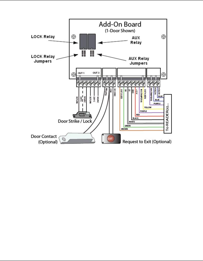
Figure 3: NetAXS-123 Add-On Board Wiring and Components
2.1 Supervised Input Wiring
The supervised inputs are located on the following terminal blocks:
Table 1: Supervised Input Terminal Blocks
Board Configuration |
Terminal Block |
|
|
1-Door (Controller Board) |
C-TB2 |
|
C-TB10 |
|
|
1-Door (Add-On Board) |
IO-TB2 |
|
|
2-Door (Add-On Board) |
IO-TB2 (as 1-door Add-On |
|
Board) |
|
IO-TB6 |
|
|
NetAXS-123 Access Control Unit Installation Guide, Document 800-05779, Revision A |
5 |
Installing the NetAXS-123 Panels
Panel Components and Descriptions
Tampers can also be supervised. They are located on the following terminal blocks:
Table 2: Supervised Tamper Terminal Blocks
Board Configuration |
Terminal Block |
|
|
1-Door (Controller Board) |
C-TB3/TMPR A |
|
C-TB4/TMPR B |
|
|
1-Door (Add-On Board) |
IO-TB3/TMPR A |
|
IO-TB4/TMPR B |
|
|
2-Door (Add-On Board) |
IO-TB3/TMPR A |
|
IO-TB4/TMPR B |
|
IO-TB7/TMPR A |
|
IO-TB8/TMPR B |
|
|
Door Status (STS) and Request to Exit (REX) for all three doors may be configured for Normally Open or Normally Closed contacts as supervised or non-supervised. Inputs 5 (generic) and 6 (power) are on C-TB10. All seven inputs on the Controller Board and four inputs on the Add-On Board have default functions, but they can be configured for general purpose inputs.
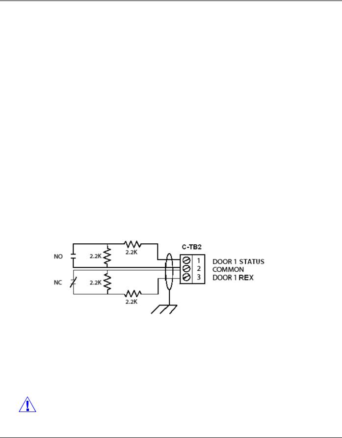
The following figure shows the typical wiring for a supervised input.
Figure 4: Typical Supervised Input Wiring Diagram
The figure above shows standard 2,200 ohm resistors. The NetAXS-123 panel accepts 1,000, 2,200, 4,700, or 10,000 ohm values. Note that both resistors must have the same value.
In addition, the Reader tampers can be supervised and capable of being used as additional inputs if the default functionality is not needed.
The wire used for the inputs should be shielded and cannot exceed 30 ohms over the entire length of the cable. Remember that the distance from the panel to the door must be doubled to determine the total resistance.
Caution: The cable shield should be grounded only at the panel earth ground. Grounding at both ends can cause ground loops which can be disruptive.
6 www.honeywell.com

Installing the NetAXS-123 Panels
Panel Components and Descriptions
Caution: The system has not been verified for compliance with UL1076 Burglar Alarm units and systems.
2.2 NetAXS-123 Access Control Unit
The NetAXS-123 panel is a one-door access control unit that you can supplement with an add-on board that supports second and third doors. The following table shows the NetAXS-123 input/output options:
Table 3: NetAXS-123 Input/Output Options
Board |
Readers |
Inputs/Outputs |
|
|
|
Controller |
1 door/2 readers |
1 lock output |
|
|
1 aux output |
|
|
1 status input |
|
|
1 Request to Exit |
|
|
2 reader tamper/AUX |
|
|
inputs |
|
|
|
Add-On (1 Door) |
1 door/2 readers |
1 lock output |
|
|
1 aux output |
|
|
1 status input |
|
|
1 Request to Exit |
|
|
2 reader tamper/AUX |
|
|
inputs |
|
|
|
Add-On (2 Door) |
2 doors/4 readers |
2 lock outputs |
|
|
2 aux outputs |
|
|
2 status inputs |
|
|
2 Request to Exits |
|
|
4 readers tamper/AUX |
|
|
inputs |
|
|
|
You can use the NetAXS-123 panel as a standalone panel with independent card and transaction storage or, with a host software upgrade, as a fully monitored online access control device.
Panel inputs are capable of four state supervision: Normal, Alarm, Short and Cut. One input is used for request to exit on each door and one input is used for door status on each door. Supervised inputs for External Power Fail and Reader Tampers are supplied as well, and they can be used as additional inputs when not required for their default purpose.
2.2.1 NetAXS-123 Add-On Board
The NetAXS-123 Add-On Board enables you to expand from one door to either two or three doors. The board easily connects to the NetAXS-123 controller board (see the NetAXS-123 Add-On Board Installation Guide (800-05787).
NetAXS-123 Access Control Unit Installation Guide, Document 800-05779, Revision A |
7 |

Installing the NetAXS-123 Panels
Panel Components and Descriptions
2.2.2 Supported Readers
Supported readers include the following:
Table 4: Readers Supported by NetAXS-123
Series |
Reader Model |
Honeywell Part |
|
|
Number |
|
|
|
OmniProx |
OP-10 |
OP10GENE |
|
|
OP10HONE |
|
|
|
|
OP-30 |
OP30GENE |
|
|
OP30HONE |
|
|
|
|
OP-40 |
OP40GENE |
|
|
OP40HONE |
|
|
|
|
OP-45 |
OP45GENE |
|
|
OP45HONE |
|
|
|
HID |
ProxPoint Plus |
6005B |
|
|
|
|
MiniProx |
HU/5365EGP00 |
|
|
|
|
Thinline II |
HU/5395CB100 |
|
|
HU/5395CG100 |
|
|
HU/5395CK100 |
|
|
|
|
ProxPro |
HU/5355AGN00 |
|
|
|
|
ProxPro II |
HU/5455BGN00 |
|
|
|
|
ProxPro K |
HU/5355AGK00 |
|
|
|
|
EntryProx |
4045CGNU0 |
|
|
|
|
MaxiProx |
HU/5375AGN00 |
|
|
|
Omni-Class |
OM40 |
OM40BHONB |
|
|
OM40GHONB |
|
|
|
|
OM41 |
OM41BHONB |
|
|
OM41GHONB |
|
|
|
|
OM55 |
OM55BHONB |
|
|
OM55GHONB |
|
|
|
|
OM70 |
OM70BHONB |
|
|
OM70GHONB |
|
|
|
8 www.honeywell.com

Installing the NetAXS-123 Panels
Panel Components and Descriptions
Series |
Reader Model |
Honeywell Part |
|
|
Number |
|
|
|
OmniAssure |
OT30 |
OT30HONA |
|
|
|
|
OT31 |
OT31HONA |
|
|
|
|
OT35 |
OT35HONA |
|
|
|
|
OT36 |
OT36HONA |
|
|
|
|
OT70 |
OT70HONA |
|
|
|
|
OT75 |
OT75HONA |
|
|
|
NexWatch |
DR 4200K |
92042000000 |
|
|
|
|
DR 4220 |
92042200000 |
|
|
|
Note: For NetAXS-123 reader specifications, see Hardware Specifications, page 60.
2.2.3 Real-Time Clock Protection
The panel RTC is backed up using a super capacitor. The super capacitor will power the real-time clock for 24 hours in the absence of primary power or backup battery.
2.3 Power Supply
The NetAXS-123 Compact Enclosure is powered by Power Over Ethernet (PoE) injector. This PoE injector can supply a total system current of 800mA to 900mA @ 12VDC. However the NetAXS-123 controller board consumes 400mA of current, and it therefore leaves 450mA of total current for the 12VDC external power. See Hardware Specifications, page 60, for further details on current limits using PoE.
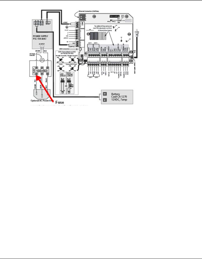
The Standard Enclosure uses a 12VDC 4A power supply with an international input of 100VAC to 240VAC. The supply also charges and monitors the condition of the battery. Wire the unswitched electrical power to the supply per the National Electrical Code as well as any local electrical codes, including the safety ground wire.
An input power indicator is supplied, and it is illuminated when input voltage is present. If the indicator is off, the input voltage is off, or too low to operate the system.
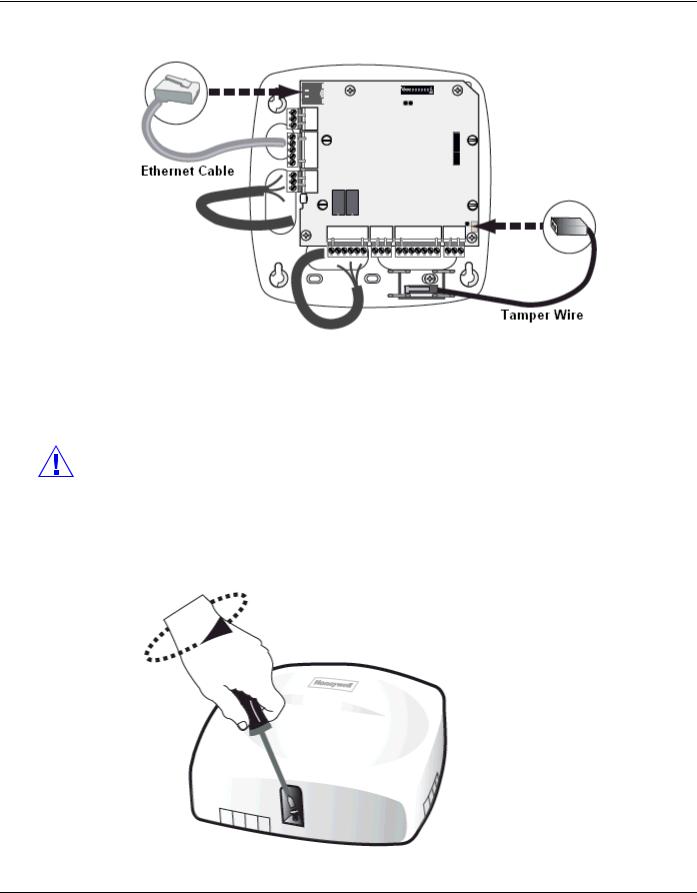
Caution: Disconnect the battery and AC power before servicing the fuse. For continued protection against the risk of electric shock and fire hazard, replace the input fuse with a GMA type fuse with the rating of 1A, 250V. The fuse is located in the lower-left corner in the cabinet, as shown below.
NetAXS-123 Access Control Unit Installation Guide, Document 800-05779, Revision A |
9 |
Installing the NetAXS-123 Panels
Panel Components and Descriptions
2.4 Battery
For the NetAXS-123 Standard Enclosure panel, one CASIL CA1270, 12 VDC, 7A-hour sealed lead-acid battery (Honeywell order number 3-000066). The battery provides standby backup power, depending upon system configuration and activity. When AC is lost, the power supply automatically switches to the backup battery for continuous 12VDC power. Replace the battery every 2 to 2.5 years, or more often if the system has a high rate of backup use.
2.5 Suppressors
Two suppressors (HAS number S-4) are required for each door lock. One suppressor is installed on the panel control board, and the second must be installed at the door lock.
10 www.honeywell.com
Installing the NetAXS-123 Panels
Installation
3.0Installation
3.1Installing the Compact Enclosure Panel
Perform the following steps to install the NetAXS-123 Compact panel:
Warning: Use a static strap whenever touching the panel to ensure protection from Electrostatic Discharge (ESD).
3.1.1 Installing on a Wall
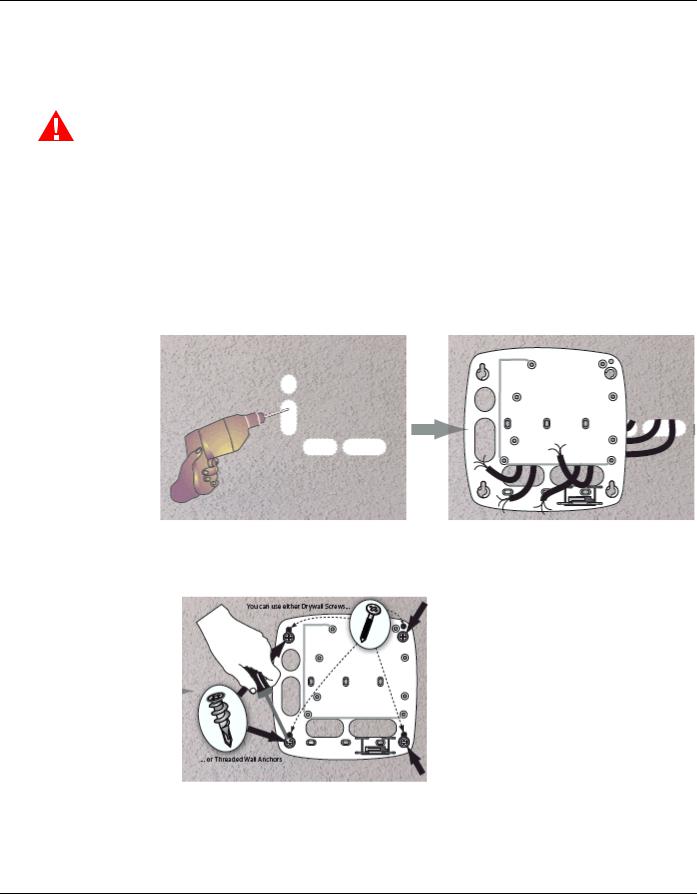
1.Review the panel layout, cable runs, and power needs.
2.Mount the enclosure’s back at the proper location on the wall:
a.Drill the screw holes in the wall, using the panel’s back as a template, and then pull the power and all I/O wires to the enclosure and through the knockout holes, and properly mark each wire for its use.
b.Screw the back of the panel to the wall, using either drywall screws or threaded wall anchors.
NetAXS-123 Access Control Unit Installation Guide, Document 800-05779, Revision A |
11 |
Installing the NetAXS-123 Panels
Installation
3. Mount the board onto the back of the panel.
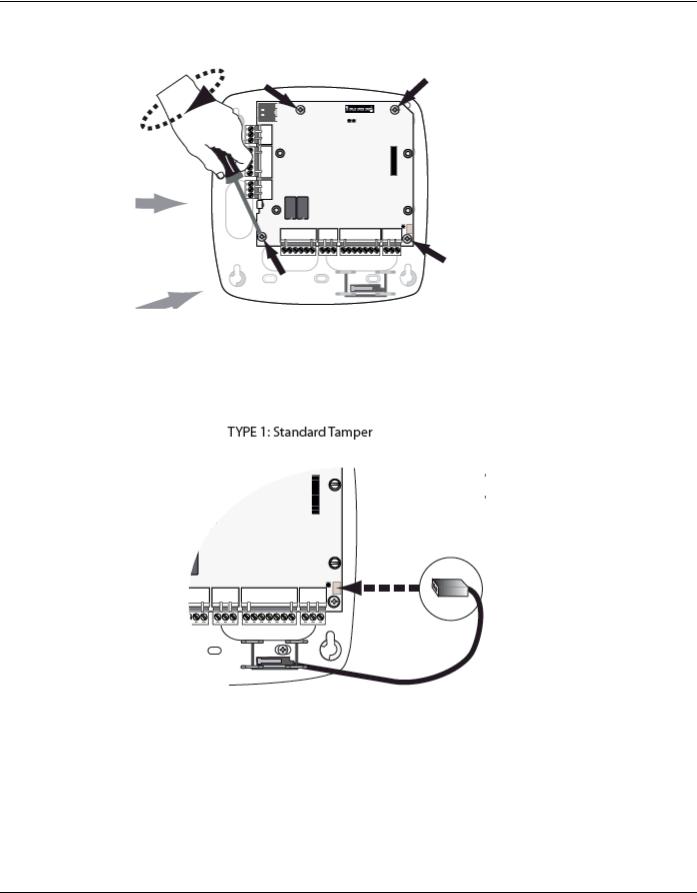
4.Choose the tamper type (standard or off-the-wall tamper) and wire the tamper.
•Wiring a standard tamper:
12 www.honeywell.com
Installing the NetAXS-123 Panels
Installation
• Wiring an off-the-wall tamper:
5. Set the tamper, using pliers at the four locations indicated below.
Warning: Do not apply power at this time.
|
|
|
|
|
|
|
|
NetAXS-123 Access Control Unit Installation Guide, Document 800-05779, Revision A |
13 |
||
Installing the NetAXS-123 Panels
Installation
6. Connect the Ethernet cable and the Tamper wire, as shown below.
7.Set DIP switch settings for the panel address, communication termination and biasing. See DIP Switch Settings, page 36.
8.Check all wiring at this time.
Caution: Improper wiring can cause damage to the NetAXS-123 at power up and result in a loss of warranty.
9. Apply power to the panel.
10.Check for the Run LED for a successful power-up. If the LED is blinking green, the panel is powered up successfully.
11.Close the cover.
14 www.honeywell.com
Installing the NetAXS-123 Panels
Installation
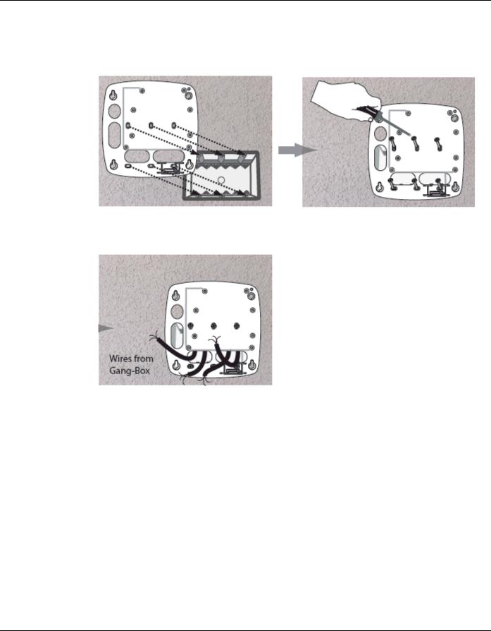
3.1.2 Installing over a Gang Box
1.Review the panel layout, cable runs, and power needs.
2.Mount the back of the panel on the gang box.
3. Pull the wires from the gang box through the knockout holes in the base of the enclosure.
4.Perform steps 3 through 10 in the preceding section ( Installing on a Wall, page 11) to complete the installation of the panel over a gang box.
NetAXS-123 Access Control Unit Installation Guide, Document 800-05779, Revision A |
15 |
Loading...