


PN: 52750:A |
ECN 05-680 |
Fire Alarm Control Panel
MS-9200UDLS MS-9200UDLSE
IMPORTANT! The SLC Manual Document #51309 must be referenced in addition to this manual when installing or servicing the Fire Alarm Control Panel.
Document #52750 A
11/04/05 Revision:
Fire Alarm System Limitations
An automatic fire alarm system–typically made up of smoke detectors, heat detectors, manual pull stations, audible warning devices, and a fire alarm control panel with remote notification capability–can provide early warning of a developing fire. Such a system, however, does not assure protection against property damage or loss of life resulting from a fire.
The Manufacturer recommends that smoke and/or heat detectors be located throughout a protected premise following the recommendations of the current edition of the National Fire Protection Association Standard 72 (NFPA 72), manufacturer's recommendations, State and local codes, and the recommendations contained in the Guide for Proper Use of System Smoke Detectors, which is made available at no charge to all installing dealers. A study by the Federal Emergency Management Agency (an agency of the United States government) indicated that smoke detectors may not go off in as many as 35% of all fires. While fire alarm systems are designed to provide early warning against fire, they do not guarantee warning or protection against fire. A fire alarm system may not provide timely or adequate warning, or simply may not function, for a variety of reasons:
Smoke detectors may not sense fire where smoke cannot reach the detectors such as in chimneys, in or behind walls, on roofs, or on the other side of closed doors. Smoke detectors also may not sense a fire on another level or floor of a building. A second-floor detector, for example, may not sense a first-floor or basement fire.
Particles of combustion or "smoke" from a developing fire may not reach the sensing chambers of smoke detectors because:
•Barriers such as closed or partially closed doors, walls, or chimneys may inhibit particle or smoke flow.
•Smoke particles may become "cold," stratify, and not reach the ceiling or upper walls where detectors are located.
•Smoke particles may be blown away from detectors by air outlets.
•Smoke particles may be drawn into air returns before reaching the detector.
The amount of "smoke" present may be insufficient to alarm smoke detectors. Smoke detectors are designed to alarm at various levels of smoke density. If such density levels are not created by a developing fire at the location of detectors, the detectors will not go into alarm.
Smoke detectors, even when working properly, have sensing limitations. Detectors that have photoelectronic sensing chambers tend to detect smoldering fires better than flaming fires, which have little visible smoke. Detectors that have ion- izing-type sensing chambers tend to detect fast-flaming fires better than smoldering fires. Because fires develop in different ways and are often unpredictable in their growth, neither type of detector is necessarily best and a given type of detector may not provide adequate warning of a fire.
Smoke detectors cannot be expected to provide adequate warning of fires caused by arson, children playing with matches (especially in bedrooms), smoking in bed, and violent explosions (caused by escaping gas, improper storage of flammable materials, etc.).
While a fire alarm system may lower insurance rates, it is not a substitute for fire insurance!
Heat detectors do not sense particles of combustion and alarm only when heat on their sensors increases at a predetermined rate or reaches a predetermined level. Rate-of-rise heat detectors may be subject to reduced sensitivity over time. For this reason, the rate-of-rise feature of each detector should be tested at least once per year by a qualified fire protection specialist. Heat detectors are designed to protect property, not life.
IMPORTANT! Smoke detectors must be installed in the same room as the control panel and in rooms used by the system for the connection of alarm transmission wiring, communications, signaling, and/or power. If detectors are not so located, a developing fire may damage the alarm system, crippling its ability to report a fire.
Audible warning devices such as bells may not alert people if these devices are located on the other side of closed or partly open doors or are located on another floor of a building. Any warning device may fail to alert people with a disability or those who have recently consumed drugs, alcohol or medication. Please note that:
•Strobes can, under certain circumstances, cause seizures in people with conditions such as epilepsy.
•Studies have shown that certain people, even when they hear a fire alarm signal, do not respond or comprehend the meaning of the signal. It is the property owner's responsibility to conduct fire drills and other training exercise to make people aware of fire alarm signals and instruct them on the proper reaction to alarm signals.
•In rare instances, the sounding of a warning device can cause temporary or permanent hearing loss.
A fire alarm system will not operate without any electrical power. If AC power fails, the system will operate from standby batteries only for a specified time and only if the batteries have been properly maintained and replaced regularly.
Equipment used in the system may not be technically compatible with the control. It is essential to use only equipment listed for service with your control panel.
Telephone lines needed to transmit alarm signals from a premise to a central monitoring station may be out of service or temporarily disabled. For added protection against telephone line failure, backup radio transmission systems are recommended.
The most common cause of fire alarm malfunction is inadequate maintenance. To keep the entire fire alarm system in excellent working order, ongoing maintenance is required per the manufacturer's recommendations, and UL and NFPA standards. At a minimum, the requirements of NFPA 72 shall be followed. Environments with large amounts of dust, dirt or high air velocity require more frequent maintenance. A maintenance agreement should be arranged through the local manufacturer's representative. Maintenance should be scheduled monthly or as required by National and/or local fire codes and should be performed by authorized professional fire alarm installers only. Adequate written records of all inspections should be kept.
PrecauLarge.PMD 01/10/2005

Installation Precautions
WARNING - Several different sources of power can be connected to the fire alarm control panel. Disconnect all sources of power before servicing. Control unit and associated equipment may be damaged by removing and/or inserting cards, modules, or interconnecting cables while the unit is energized. Do not attempt to install, service, or operate this unit until this manual is read and understood.
CAUTION - System Reacceptance Test after Software Changes. To ensure proper system operation, this product must be tested in accordance with NFPA 72 after any programming operation or change in site-specific software. Reacceptance testing is required after any change, addition or deletion of system components, or after any modification, repair or adjustment to system hardware or wiring.
All components, circuits, system operations, or software functions known to be affected by a change must be 100% tested. In addition, to ensure that other operations are not inadvertently affected, at least 10% of initiating devices that are not directly affected by the change, up to a maximum of 50 devices, must also be tested and proper system operation verified.
This system meets NFPA requirements for indoor dry operation at 0-49° C/32-120° F and at a relative humidity of 93 ±2% RH (non-condensing) at 32 ±2° C/90 ±3° F. However, the useful life of the system's standby batteries and the electronic components may be adversely affected by extreme temperature ranges and humidity. Therefore, it is recommended that this system and all peripherals be installed in an environment with a nominal room temperature of 15-27° C/60-80° F.
Verify that wire sizes are adequate for all initiating and indicating device loops. Refer to manual Specifications section for maximum allowable I.R. drop from the specified device voltage.
Adherence to the following will aid in problem-free installation with long-term reliability:
Like all solid state electronic devices, this system may operate erratically or can be damaged when subjected to lightning-induced transients. Although no system is completely immune from lightning transients and interferences, proper grounding will reduce susceptibility. Overhead or outside aerial wiring is not recommended, due to an increased susceptibility to nearby lightning strikes. Consult with the Technical Services Department if any problems are anticipated or encountered.
Disconnect AC power and batteries prior to removing or inserting circuit boards. Failure to do so can damage circuits.
Remove all electronic assemblies prior to any drilling, filing, reaming, or punching of the enclosure. When possible, make all cable entries from the sides or rear. Before making modifications, verify that they will not interfere with battery, transformer, and printed circuit board location.
Do not tighten screw terminals more than 9 in-lbs. Over-tightening may damage threads, resulting in reduced terminal contact pressure and difficulty with screw terminal removal.
This system contains static-sensitive components.
Always ground yourself with a proper wrist strap before handling any circuits so that static charges are removed from the body. Use static-suppressive packaging to protect electronic assemblies removed from the unit.
Follow the instructions in the installation, operating, and programming manuals. These instructions must be followed to avoid damage to the control panel and associated equipment. FACP operation and reliability depend upon proper installation by authorized personnel.
FCC Warning
WARNING: This equipment generates, uses, and can ra- |
Canadian Requirements |
|
diate radio frequency energy and if not installed and used |
This digital apparatus does not exceed the Class A |
|
in accordance with the instruction manual, may cause in- |
limits for radiation noise emissions from digital |
|
terference to radio communications. It has been tested |
apparatus set out in the Radio Interference Regulations |
|
and found to comply with the limits for class A computing |
of the Canadian Department of Communications. |
|
device pursuant to Subpart B of Part 15 of FCC Rules, |
Le present appareil numerique n'emet pas de bruits |
|
which is designed to provide reasonable protection against |
||
radioelectriques depassant les limites applicables aux |
||
such interference when operated in a commercial environ- |
||
appareils numeriques de la classe A prescrites dans le |
||
ment. Operation of this equipment in a residential area is |
||
Reglement sur le brouillage radioelectrique edicte par le |
||
likely to cause interference, in which case the user will be |
||
ministere des Communications du Canada. |
||
required to correct the interference at their own |
||
|
||
expense. |
|
PrecauLarge.PMD 01/10/2005
Notes
4 |
MS-9200UDLS PN 52750:A 11/04/05 |
Table of Contents
SECTION 1: Product Description ........................................................................................................................ |
12 |
1.1: Features and Options................................................................................................................................... |
12 |
1.2: Specifications .............................................................................................................................................. |
13 |
1.2.1: Current Availability........................................................................................................................... |
15 |
1.3: Controls and Indicators ............................................................................................................................... |
16 |
1.4: Circuits ........................................................................................................................................................ |
17 |
1.5: Digital Alarm Communicator/Transmitter.................................................................................................. |
17 |
1.6: Components................................................................................................................................................. |
18 |
1.6.1: Intelligent Addressable Detectors: Newer Series.............................................................................. |
18 |
1.6.2: Intelligent Addressable Modules: Newer Series ............................................................................... |
19 |
1.6.3: 300 Series Intelligent Addressable Devices...................................................................................... |
19 |
1.6.4: Addressable Device Accessories....................................................................................................... |
19 |
1.7: Optional Modules........................................................................................................................................ |
20 |
1.8: Accessories.................................................................................................................................................. |
20 |
1.8.1: PK-CD Programming Utility ............................................................................................................ |
20 |
1.8.2: Dress Panel........................................................................................................................................ |
20 |
1.8.3: Battery Box ....................................................................................................................................... |
21 |
1.8.4: Battery Charger ................................................................................................................................. |
21 |
1.8.4.1 CHG-75 Battery Charger ........................................................................................................ |
21 |
1.8.4.2 CHG-120F Battery Charger .................................................................................................... |
21 |
1.8.5: Annunciators ..................................................................................................................................... |
22 |
1.9: Getting Started............................................................................................................................................. |
23 |
1.10: Telephone Requirements and Warnings .................................................................................................... |
24 |
1.10.1: Telephone Circuitry......................................................................................................................... |
24 |
1.10.2: Digital Communicator..................................................................................................................... |
24 |
1.10.3: Telephone Company Rights and Warnings ..................................................................................... |
25 |
1.10.4: For Canadian Applications.............................................................................................................. |
26 |
SECTION 2: Installation ....................................................................................................................................... |
27 |
2.1: Mounting Backbox...................................................................................................................................... |
27 |
2.2: Mounting Transformer ................................................................................................................................ |
28 |
2.3: Power........................................................................................................................................................... |
31 |
2.3.1: AC Power and Earth Ground Connection......................................................................................... |
31 |
2.3.2: Battery Power.................................................................................................................................... |
31 |
2.3.3: Special Application DC Power Output Connection.......................................................................... |
31 |
2.4: Relays .......................................................................................................................................................... |
32 |
2.5: Notification Appliance Circuits .................................................................................................................. |
32 |
2.5.1: Configuring NACs ............................................................................................................................ |
33 |
2.5.2: Style Y (Class B) NAC Wiring ......................................................................................................... |
33 |
2.5.3: Style Z (Class A) NAC Wiring ........................................................................................................ |
34 |
2.6: Remote Synchronization Output ................................................................................................................. |
34 |
2.7: UL Power-limited Wiring Requirements .................................................................................................... |
35 |
2.8: Digital Communicator................................................................................................................................. |
36 |
2.9: Optional Module Installation ...................................................................................................................... |
37 |
2.9.1: 4XTMF Transmitter Module Installation.......................................................................................... |
38 |
2.9.2: Printer/PC.......................................................................................................................................... |
40 |
2.9.3: Digital Communicator and Annunciators ......................................................................................... |
41 |
2.9.3.1 ACM-8RF Relay Control Module .......................................................................................... |
41 |
2.9.3.2 ACS and AFM Series Annunciators ....................................................................................... |
41 |
SECTION 3: Programming .................................................................................................................................. |
42 |
3.1: Programming Data Entry ............................................................................................................................ |
42 |
3.2: User Programming ...................................................................................................................................... |
43 |
3.3: Initial Power-up........................................................................................................................................... |
44 |
MS-9200UDLS P/N: 52750:A 11/04/05 |
5 |
Table of Contents |
|
3.4: Programming Screens Description .............................................................................................................. |
44 |
3.5: Programming and Passwords ...................................................................................................................... |
44 |
3.6: Master Programming Level......................................................................................................................... |
46 |
3.6.1: Autoprogram ..................................................................................................................................... |
47 |
3.6.2: Point Program.................................................................................................................................... |
48 |
3.6.2.1 Detector Programming ............................................................................................................ |
48 |
3.6.2.1.1 Add Detector ........................................................................................................................ |
48 |
3.6.2.1.2 Delete Detector ..................................................................................................................... |
49 |
3.6.2.1.3 Edit Detector ........................................................................................................................ |
49 |
3.6.2.2 Module Programming ............................................................................................................. |
58 |
3.6.2.2.1 Add Module ......................................................................................................................... |
58 |
3.6.2.2.2 Delete Module ...................................................................................................................... |
59 |
3.6.2.2.3 Edit Module Screen for Monitor Module ............................................................................. |
59 |
3.6.2.2.4 Edit Module Screen for Control Modules ............................................................................ |
68 |
3.6.3: Zone Setup......................................................................................................................................... |
75 |
3.6.3.1 Enable ...................................................................................................................................... |
75 |
3.6.3.2 Disable ..................................................................................................................................... |
76 |
3.6.3.3 Zone 97, 98 and 99 .................................................................................................................. |
76 |
3.6.3.4 Zones Installed ........................................................................................................................ |
77 |
3.6.3.5 Zones Enabled ......................................................................................................................... |
77 |
3.6.3.6 Zones Disabled ........................................................................................................................ |
77 |
3.6.3.7 Zone Type ............................................................................................................................... |
78 |
3.6.3.8 Zones Available ...................................................................................................................... |
79 |
3.6.4: Loop Setup ........................................................................................................................................ |
79 |
3.6.4.1 Style ......................................................................................................................................... |
79 |
3.6.4.2 Loop Protocol .......................................................................................................................... |
79 |
3.6.5: System Setup ..................................................................................................................................... |
80 |
3.6.5.1 Trouble Reminder ................................................................................................................... |
81 |
3.6.5.2 Banner ..................................................................................................................................... |
81 |
3.6.5.3 Time-Date ............................................................................................................................... |
82 |
3.6.5.3.1 Time ..................................................................................................................................... |
82 |
3.6.5.3.2 Date ...................................................................................................................................... |
83 |
3.6.5.3.3 Clock Format ........................................................................................................................ |
83 |
3.6.5.3.4 Daylight Savings Time ......................................................................................................... |
83 |
3.6.5.4 Timers ..................................................................................................................................... |
84 |
3.6.5.4.1 PAS (Positive Alarm Sequence) Delay ................................................................................ |
84 |
3.6.5.4.2 Pre-signal Delay ................................................................................................................... |
85 |
3.6.5.4.3 Waterflow Delay .................................................................................................................. |
85 |
3.6.5.4.4 AC Loss Delay ..................................................................................................................... |
86 |
3.6.5.5 NAC (Notification Appliance Circuit) .................................................................................... |
86 |
3.6.5.5.1 Enabled ................................................................................................................................. |
87 |
3.6.5.5.2 Type ...................................................................................................................................... |
88 |
3.6.5.5.3 Silenceable ........................................................................................................................... |
88 |
3.6.5.5.4 Auto Silence ......................................................................................................................... |
89 |
3.6.5.5.5 Coding (only for NACs not programmed as Sync Strobe Type) ......................................... |
89 |
3.6.5.5.6 Zone ...................................................................................................................................... |
91 |
3.6.5.5.7 Silence Inhibited ................................................................................................................... |
91 |
3.6.5.5.8 Sync Type ............................................................................................................................. |
91 |
3.6.5.6 Relays ...................................................................................................................................... |
92 |
3.6.5.7 Canadian Option ...................................................................................................................... |
93 |
3.6.5.8 Waterflow Silenceable ............................................................................................................ |
93 |
3.6.6: Verify Loop ....................................................................................................................................... |
93 |
3.6.7: History............................................................................................................................................... |
94 |
3.6.7.1 View Events ............................................................................................................................ |
94 |
3.6.7.2 Erase History ........................................................................................................................... |
94 |
3.6.8: Walktest ............................................................................................................................................. |
95 |
6 |
MS-9200UDLS P/N: 52750:A 11/04/05 |
Table of Contents |
|
3.6.9: Option Modules................................................................................................................................ |
96 |
3.6.9.1 Annunciators/UDACT ............................................................................................................ |
96 |
3.6.9.2 Onboard DACT ....................................................................................................................... |
97 |
3.6.9.2.1 Onboard DACT Enable ........................................................................................................ |
97 |
3.6.9.2.2 Primary Phone ...................................................................................................................... |
98 |
3.6.9.2.3 Secondary Phone .................................................................................................................. |
98 |
3.6.9.2.4 Service Terminal .................................................................................................................. |
99 |
3.6.9.2.5 Central Station ...................................................................................................................... |
101 |
3.6.9.2.6 Trouble Call Limit (Dialer Runaway Prevention) ............................................................... |
102 |
3.6.9.2.7 Manual Dial Mode ............................................................................................................... |
114 |
3.6.9.3 Printer/PC ................................................................................................................................ |
115 |
3.6.10: Password Change ............................................................................................................................ |
116 |
3.6.11: Clear Program ................................................................................................................................. |
117 |
3.6.12: Program Check................................................................................................................................ |
118 |
3.7: Maintenance Programming Level ............................................................................................................... |
120 |
3.7.1: Disable Point ..................................................................................................................................... |
121 |
3.7.2: History............................................................................................................................................... |
122 |
3.7.3: Program Check.................................................................................................................................. |
123 |
3.7.4: Walktest............................................................................................................................................. |
124 |
3.7.5: System............................................................................................................................................... |
124 |
3.7.6: Zone Setup ........................................................................................................................................ |
126 |
SECTION 4: Operating Instructions .................................................................................................................... |
128 |
4.1: Panel Control Buttons ................................................................................................................................. |
128 |
4.1.1: Acknowledge/Step ............................................................................................................................ |
128 |
4.1.2: Alarm Silence.................................................................................................................................... |
128 |
4.1.3: Drill/Hold 2 Sec ................................................................................................................................ |
128 |
4.1.4: Reset.................................................................................................................................................. |
128 |
4.2: LED Indicators ............................................................................................................................................ |
129 |
4.3: Normal Operation........................................................................................................................................ |
130 |
4.4: Trouble Operation ....................................................................................................................................... |
130 |
4.5: Alarm Operation.......................................................................................................................................... |
132 |
4.6: Supervisory Operation................................................................................................................................. |
133 |
4.7: Process Monitor Operation.......................................................................................................................... |
134 |
4.8: Hazard/Tornado Condition Operation ......................................................................................................... |
134 |
4.9: Medical Alert Condition Operation............................................................................................................. |
134 |
4.10: NAC Operation ......................................................................................................................................... |
134 |
4.11: Programmed Zone Operation .................................................................................................................... |
135 |
4.12: Disable/Enable Operation ......................................................................................................................... |
135 |
4.13: Waterflow Circuits Operation ................................................................................................................... |
135 |
4.14: Detector Functions .................................................................................................................................... |
135 |
4.15: Time Functions: Real-Time Clock ............................................................................................................ |
135 |
4.16: Synchronized NAC Operation .................................................................................................................. |
136 |
4.17: Coded Operation ....................................................................................................................................... |
136 |
4.18: Presignal .................................................................................................................................................... |
136 |
4.19: Positive Alarm Sequence .......................................................................................................................... |
137 |
4.20: Special System Timers .............................................................................................................................. |
138 |
4.20.1: Silence Inhibit Timer....................................................................................................................... |
138 |
4.20.2: Autosilence Timer ........................................................................................................................... |
138 |
4.20.3: Trouble Reminder ........................................................................................................................... |
138 |
4.20.4: Waterflow Retard Timer.................................................................................................................. |
138 |
4.20.5: Alarm Verification (None or One Minute)...................................................................................... |
139 |
4.21: Walktest ..................................................................................................................................................... |
139 |
4.22: Read Status ................................................................................................................................................ |
140 |
4.22.1: System Point ................................................................................................................................... |
141 |
MS-9200UDLS P/N: 52750:A 11/04/05 |
7 |
Table of Contents |
|
4.22.2: Zones ............................................................................................................................................... |
142 |
4.22.3: Power............................................................................................................................................... |
143 |
4.22.4: Trouble Reminder............................................................................................................................ |
144 |
4.22.5: Timers.............................................................................................................................................. |
144 |
4.22.6: NAC ................................................................................................................................................ |
145 |
4.22.7: Relays .............................................................................................................................................. |
145 |
4.22.8: Program Check................................................................................................................................ |
146 |
4.22.9: History............................................................................................................................................. |
146 |
4.22.10: Annunciators ................................................................................................................................. |
147 |
4.22.11: Phone Line..................................................................................................................................... |
147 |
4.22.12: Central Station............................................................................................................................... |
148 |
4.22.13: Service Terminal............................................................................................................................ |
149 |
4.22.14: Printer/PC ...................................................................................................................................... |
149 |
4.22.15: Print ............................................................................................................................................... |
150 |
4.22.16: Time-Date...................................................................................................................................... |
152 |
SECTION 5: Central Station Communications ................................................................................................... |
153 |
5.1: Transmittal Priorities ................................................................................................................................... |
156 |
SECTION 6: Remote Site Upload/Download ....................................................................................................... |
158 |
6.1: Downloading Program................................................................................................................................. |
158 |
6.1.1: Security Features ............................................................................................................................... |
159 |
6.2: Downloading Initiated at a Service Terminal.............................................................................................. |
161 |
6.3: Uploading Initiated at a Service Terminal................................................................................................... |
162 |
SECTION 7: Power Supply Calculations ............................................................................................................. |
163 |
7.1: Overview ..................................................................................................................................................... |
163 |
7.2: Calculating the AC Branch Circuit.............................................................................................................. |
163 |
7.3: Calculating the System Current Draw......................................................................................................... |
164 |
7.3.1: Overview ........................................................................................................................................... |
164 |
7.3.2: How to Use Table 7.3 on page 165 to Calculate System Current Draw ........................................... |
164 |
7.4: Calculating the Battery Size ........................................................................................................................ |
166 |
7.4.1: NFPA Battery Requirements ............................................................................................................. |
166 |
7.4.2: Selecting and Locating Batteries....................................................................................................... |
166 |
APPENDIX A: Software Zones ............................................................................................................................ |
167 |
A.1: Correlations ............................................................................................................................................... |
167 |
APPENDIX B: Default Programming ................................................................................................................. |
173 |
APPENDIX C: NFPA Standard-Specific Requirements ................................................................................... |
174 |
APPENDIX D: Wire Requirements ..................................................................................................................... |
178 |
APPENDIX E: HVAC Control ............................................................................................................................. |
179 |
E.1: Control Module Operation ......................................................................................................................... |
179 |
E.1.1: HVAC SHUTDN ............................................................................................................................. |
179 |
E.2: Monitor Module Operation ........................................................................................................................ |
179 |
E.2.1: HVAC RESTART ........................................................................................................................... |
179 |
E.2.2: HVAC OVRRIDE ........................................................................................................................... |
180 |
8 |
MS-9200UDLS P/N: 52750:A 11/04/05 |

It is imperative that the installer understand the requirements of the Authority Having Jurisdiction (AHJ) and be familiar with the standards set forth by the following regulatory agencies:
•Underwriters Laboratories Standards
•NFPA 72 National Fire Alarm Code
•CAN/ULC - S527-99 Standard for Control Units for Fire Alarm Systems
Before proceeding, the installer should be familiar with the following documents.
NFPA Standards
NFPA 72 National Fire Alarm Code
NFPA 70 National Electrical Code
Underwriters Laboratories Documents:
UL 38 Manually Actuated Signaling Boxes
UL 217 Smoke Detectors, Single and Multiple Station
UL 228 Door Closers–Holders for Fire Protective Signaling Systems
UL 268 Smoke Detectors for Fire Protective Signaling Systems
UL 268A Smoke Detectors for Duct Applications
UL 346 Waterflow Indicators for Fire Protective Signaling Systems
UL 464 Audible Signaling Appliances
UL 521 Heat Detectors for Fire Protective Signaling Systems
UL 864 Standard for Control Units for Fire Protective Signaling Systems
UL 1481 Power Supplies for Fire Protective Signaling Systems
UL 1610 Central Station Burglar Alarm Units
UL 1638 Visual Signaling Appliances
UL 1971 Signaling Devices for Hearing Impaired
CAN/ULC - S524-01 Standard for Installation of Fire Alarm Systems
Other:
EIA-232E Serial Interface Standard
EIA-485 Serial Interface Standard
NEC Article 250 Grounding
NEC Article 300 Wiring Methods
NEC Article 760 Fire Protective Signaling Systems
Applicable Local and State Building Codes
Requirements of the Local Authority Having Jurisdiction (LAHJ)
Fire-Lite Documents: |
|
Fire-LiteDevice Compatibility |
Document #15384 |
SLC Wiring Manual |
Document #51309 |
AFM-16ATF & AFM-32AF |
Document #15970 |
AFM-16AF Annunciator |
Document #15210 |
ACS Series Annunciators |
Document #51480 |
CHG-120F Battery Charger |
Document #50888 |
CHG-75 Battery Charger |
Document #51315 |
LDM Series Lamp Driver Modules |
Document #50055 |
LCD-80F Remote Fire Annunciator |
Document #51338 |
ACM-8RF Relay Control Module |
Document #50362 |
This product has been certified to comply with the requirements in the Standard for Control Units and Accessories for Fire Alarm Systems, UL 864, 9th Edition. Operation of this product with products not tested for UL 864, 9th Edition has not been evaluated. Such operation requires the approval of the local Authority Having Jurisdiction (AHJ).
MS-9200UDLS PN 52750:A 11/04/05 |
9 |
10
11/04/05 52750:A PN 9200UDLS-MS
|
|
|
|
|
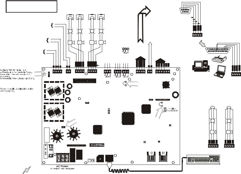
Notification Appliance Circuits |
|
|
|
|
|
|
|
|
|
|
EIA-232 |
|||||||||||||
|
|
|
|
NAC #1, #2, #3 & #4, Style Y (Class B) (Supervised, Power Limited) |
|
|
|
|
|
|
|
|
|
|
|||||||||||||||
Basic System Connections |
|
|
|
|
|
|
|
|
|
to printer or |
|||||||||||||||||||
(Special Application) 2.5 amps max. per circuit. JP6 configured |
|
|
|
|
|
|
|
|
|
||||||||||||||||||||
|
|
|
|
|
|
|
|
personal computer |
|||||||||||||||||||||
|
|
|
for Class B using NACKEY card. |
|
|
|
|
|
|
|
|
|
|||||||||||||||||
|
|
|
|
|
(See Style Z illustrated near right edge of board). |
|
|
|
|
|
|
|
|
|
|
(nonsupervised) |
|||||||||||||
|
|
|
|
|
NAC #1 |
NAC #3 |
|
NAC #4 |
NAC #2 |
|
|
|
|
|
|
|
|
For EDP-listed equipment or |
|||||||||||
|
|
|
|
|
|
|
|
|
|
|
|
|
|
personal computer with FACP |
|||||||||||||||
|
|
|
|
|
|
|
|
|
|
|
|
|
|
|
|
ELRs 4.7K, ½W |
|
|
|
|
|
|
|
Upload/Download Utility. |
|||||
Remote Synchronization Output |
|
|
|
|
+ |
|
+ |
|
|
|
+ |
|
|
+ |
|
|
|
|
|
|
|
|
50 foot maximum within same room. |
||||||
|
|
|
|
|
|
|
|
|
|
|
|
|
|
|
|
|
|
|
|
|
|
|
|
||||||
Special Application Power |
|
|
|
|
|
|
|
|
|
|
|
|
|
|
|
2 Programmable Relays & |
|
|
|
|
|
|
|
|
|
|
|||
24 VDC filtered, supervised and power-limited. |
|
2 |
|
|
|
|
|
|
|
|
|
|
|
|
|
|
|
|
|
|
|
|
|
|
|||||
0.040 amps maximum, follows NAC1 control circuit. |
|
|
|
|
|
|
|
|
|
|
|
|
1 Fixed Trouble Relay |
|
|
|
|
|
|
|
|
|
|
||||||
1 |
|
|
|
|
|
|
|
|
|
|
|
|
|
|
|
|
|
|
|
|
|
|
|||||||
Requires 4.7kohm End-of-Line resistor. |
|
|
|
|
|
|
|
|
|
|
|
|
|
|
Nonsupervised relay contacts |
|
|
|
|
|
|
|
|
|
|
|
|||
|
|
|
|
|
|
|
|
|
|
|
|
|
|
|
|
|
|
|
|
|
|
|
|
|
|
||||
|
|
|
|
|
|
|
|
|
|
|
|
|
|
|
|
|
|
|
|
|
|
|
|
|
|
|
|||
Special Application DC Power Outputs (24 VDC) |
|
+ |
|
+ |
|
|
|
+ |
|
|
+ |
Contact Ratings: |
|
|
|
|
|
|
|
|
|
|
|
|
|||||
|
|
|
|
|
|
|
2.0 amps @ 30 VDC (resistive) |
|
|
|
|
|
|
|
|
|
|
|
|||||||||||
Nonsupervised, power-limited circuits |
|
|
|
|
|
|
|
|
|
|
|
|
|
|
|
0.5 amps @ 30 VAC (resistive) |
|
|
|
|
|
ACS (EIA-485) |
|
|
|
||||
Supervise with a power supervision relay A77-716B |
4 |
|
|
|
|
|
|
|
|
|
|
|
|
|
Contacts shown below in normal |
|
|
|
|
|
to ACS Annunc. |
|
|
|
|||||
Resettable Power - 24 VDC filtered, power-limited |
|
|
|
|
|
|
|
|
|
|
|
|
|
|
|
|
|
|
(power-limited, |
|
|
|
|||||||
3 |
|
|
|
|
|
|
|
|
|
|
|
|
|
condition (AC power with no alarm, |
|
|
|
|
supervised) |
|
|
|
|||||||
(0.500 amps maximum) to smoke detectors (IDC). |
|
|
|
+ |
|
+ |
|
|
|
+ |
|
|
+ |
|
|
|
|
|
|
|
|||||||||
|
|
|
|
|
|
|
|
|
trouble or supervisory activity). |
|
|
|
|
|
|
|
SLC Loop |
||||||||||||
Supervision required. |
|
|
|
|
|
|
|
|
|
|
|
|
|
|
|
|
|
OR |
|
|
|
||||||||
|
|
|
|
|
|
|
|
|
|
|
|
|
|
|
|
A Fail Safe Trouble |
NC NO C |
|
|
|
|
|
(supervised) |
||||||
|
|
|
|
|
|
|
|
|
|
|
|
|
|
|
|
|
|
|
|
|
|
|
|||||||
Nonresettable or Resettable Power |
2 |
|
|
|
|
|
|
|
|
|
|
|
|
|
|
relay switches to the |
|
|
|
TERM |
|
Refer to the SLC Wiring |
|||||||
Jumper selectable by JP4, 24 VDC filtered, |
|
|
|
|
|
|
|
|
|
|
|
|
|
|
NO position during |
|
|
(EIA-485) |
Manual for detailed |
||||||||||
power-limited (0.500 amps maximum) |
1 |
|
|
|
|
|
|
|
|
|
|
|
|
|
|
trouble conditions and |
|
to LCD-80F |
information on wiring |
||||||||||
|
|
|
|
|
|
|
|
|
|
|
|
|
|
|
under loss of all power. |
|
addressable devices |
||||||||||||
Supervision required. Nonresettable |
|
|
|
|
|
|
|
|
|
|
|
|
|
|
|
|
|
|
|
|
|
||||||||
Power suitable for powering annunciators, |
|
|
|
|
|
|
|
|
|
|
|
|
|
|
(*Factory default relay programming) |
|
|
|
|
|
|
for Style 4, 6 and 7. |
|||||||
|
|
|
|
|
|
|
|
|
|
|
|
|
|
|
|
|
|
|
|
|
|
|
|
|
|||||
Resettable Power suitable for powering |
|
|
|
|
|
|
|
|
|
|
|
|
|
|
Supervisory* |
Alarm* |
Trouble |
|
O |
|
O |
|
|
|
|
|
|
|
|
smoke detectors.. |
|
|
|
|
|
|
B B B |
B |
B |
B B |
B |
|
I |
I |
|
|
|
|
|
|
|||||||||
|
|
|
|
|
|
|
NO NC C |
NO NC C |
NC NO C |
|
U |
U |
|
|
|
|
|
|
|||||||||||
|
|
|
+ - |
+ - |
+ |
- |
+ |
+ |
- |
- |
+ |
+ |
- |
- |
NAC |
|
|
|
|
T |
N |
T |
N |
+ |
- |
B A |
B A A B |
||
|
|
|
1 |
3 |
3 |
1 |
2 |
4 |
4 |
2 |
Number |
N |
|
|
|
+ |
+ |
- |
- |
+ |
+ |
- - |
|
||||||
|
|
|
TB1 |
|
TB2 |
|
TB3 |
|
|
TB4 |
|
|
|
TB7 NO NC C TB5 |
TB6 |
TB8 OUT+ IN+ OUTIN- |
TB9 ACS |
TB10 |
SLC |
SLC |
SLC SLC |
SHIELD |
|||||||
|
|
|
|
|
|
|
|
|
|
B+ |
A+ B- A- |
A B |
|||||||||||||||||
|
|
JP4 |
|
|
|
|
|
|
|
|
|
|
|
|
|
NI |
NO NC C |
NO NC C |
|
|
|
|
|
|
|
|
|
|
|
|
|
|
|
|
|
|
|
|
|
|
|
|
|
|
|
|
|
|
|
|
|
|
|
|
|
|
|
|
|
|
|
1 |
+ 24V - |
+ 24V - |
+ |
- |
B+ A+ A- B- |
B+ A+ A- B- |
|
RELAY 3 |
RELAY 1 |
RELAY 2 |
|
|
|
|
|
|
|
|
|
|
|
||||||
|
|
2 |
|
|
|
|
|
|
|
|
|
|
|
|
|||||||||||||||
|
|
3 |
NON-RST |
RST |
REMOTE PWR |
1B+ 3B+ 3B1B- |
2B+ 4B+ 4B2B- |
|
|
|
|
|
|
|
|
|
|
|
|
|
|
|
|||||||
|
|
POWER |
POWER |
SUPPLY SYNC |
NAC 1 CLASSA |
NAC 2 CLASS A |
|
|
|
|
|
|
|
|
|
|
|
|
|
|
|
||||||||
|
|
|
|
|
NAC 1 & 3 CLASS B |
NAC 2 & 4 CLASS B |
|
|
|
|
|
|
|
|
|
|
|
|
|
|
|
||||||||
|
|
|
|
|
|
JP6 |
|
|
|
JP2 |
|
|
|
|
|
|
|
|
|
|
|
||||||||
|
|
|
|
|
|
|
|
|
|
|
|
|
|
|
|
|
|
|
|
|
|
|
|
|
|
|
|
||
|
|
|
|
|
|
|
|
|
|
|
|
|
|
|
|
|
|
|
|
|
Cut this jumper to enable |
|
|
||||||
|
|
|
|
|
|
|
Configure NACs for Class A or |
|
|
|
|
|
Supervisory relay when |
|
|
||||||||||||||
|
|
|
|
|
|
|
|
|
|
|
|
4XTMF module is installed |
|
||||||||||||||||
|
|
|
|
|
|
|
Class B wiring using NACKEY |
|
|
|
|
|
|
||||||||||||||||
|
|
|
|
|
|
|
|
|
|
|
|
|
|
|
|
|
|
|
|
|
|||||||||
|
|
|
|
|
|
|
card. Factory default is Class B. |
|
|
|
|
|
|
|
|
|
|
|
|
|
|
||||||||
|
|
|
|
|
|
|
|
|
|
REMOVE TO |
|
|
|
|
|
|
|
|
|
|
|
|
|
|
4XTMF |
|
|||
|
|
|
|
|
|
|
|
|
|
DISABLE GND. FLT. |
|
|
|
|
|
|
|
|
|
|
J5 |
J6 |
|
|
|||||
|
|
|
|
|
|
|
|
|
|
|
|
|
|
|
|
|
|
|
|
|
|
|
|
||||||
Important! Removing Ground |
|
|
|
|
|
|
|
|
|
|
JP7 |
|
|
|
|
|
|
|
|
|
|
|
|
|
|
|
|
||
|
|
|
|
|
|
To disable ground fault detection, |
Flash Memory Load Enable Switch. |
|
|
JP3 |
|
|
|||||||||||||||||
Fault Disable Jumper JP7 |
|
|
|
|
|
|
UP is normal position for switch. |
|
|
|
|
CUT TO |
|
|
|||||||||||||||
|
|
|
|
|
|
remove jumper/shunt from JP7 |
SW1 DOWN position allows loading of |
|
|
|
|
|
|||||||||||||||||
|
|
|
|
|
|
|
|
|
MONITOR |
|
|
||||||||||||||||||
voids UL/NFPA Style/Class |
|
|
|
|
|
|
|
|
|
|
|
|
|
|
|
factory software upgrades. |
|
|
|
|
|
4XTMF |
|
|
|||||
identifications for circuits. |
|
|
|
|
|
|
|
|
|
|
|
|
|
|
|
|
|
|
|
|
|
|
|
|
|
|
|
J7 |
|
Remove jumper JP7 only |
|
|
|
|
|
|
|
Remove this jumper |
|
|
|
|
|
|
|
|
|
|
|
|
|
|
|
|
|||||
with the approval of the AHJ |
|
|
|
|
|
|
|
to disable the FACP |
|
|
|
|
|
|
|
|
|
|
|
|
|
|
|
|
|||||
|
|
|
|
|
|
|
battery charger when |
|
|
|
|
|
|
|
|
Cut this jumper to supervise |
|
||||||||||||
(Authority Having Jurisdiction) |
|
|
|
|
JP5 |
|
|
using external charger. |
|
|
|
|
|
|
|
|
the 4XTMF module when |
|
|||||||||||
J11 |
|
|
|
|
|
|
|
|
|
|
|
|
|
|
|
|
|
|
|
|
installed (see J5 & J6) |
|
|
||||||
|
|
|
|
|
|
|
|
|
|
|
|
|
|
|
|
|
|
|
|
|
|
|
|
|
|
|
KISSOFF |
||
|
|
|
|
|
|
|
|
|
|
|
|
|
|
|
|
|
|
|
|
|
|
|
|
|
|
|
|
|
|
Transformer 2 Connector |
VOLTAGE HIGH |
|
|
|
|
|
|
|
|
|
|
|
|
|
|
|
|
|
|
|
|
|
|
|
|
|
|
|
|
TRANSFORMER2 |
CAUTION! |
|
|
|
|
|
|
|
|
|
|
|
|
|
|
|
|
|
|
|
PRI. ACTIVE |
SEC. ACTIVE |
|
||||||
|
|
|
LCD DISPLAY |
|
|
|
|
|
|
|
|
|
|
|
|
|
|
|
|
|
|
|
|
|
|||||
|
|
|
|
|
J1 |
|
|
J4 |
|
|
|
KEYPAD |
|
|
|
|
|
|
|
|
|
|
|
|
|
||||
|
|
|
|
|
|
|
|
|
|
|
|
|
I/F |
|
|
|
|
|
|
|
|
|
|
|
|
|
|||
Transformer 1 Connector |
|
|
TB11 |
|
|
|
|
|
|
|
|
|
|
|
|
|
|
|
|
|
|
|
J13 |
|
|
J12 |
|
||
|
|
|
|
|
|
|
|
|
|
|
|
|
|
|
|
|
|
|
|
|
|
|
|
|
|
|
|
|
|
TRANSFORMER1 |
|
|
|
|
|
|
|
|
|
|
|
|
|
|
|
J3 |
|
|
|
|
|
|
|
|
|
|
|
|
|
|
|
|
|
|
|
|
|
|
|
|
J9 |
|
|
|
I I |
|
|
|
|
|
|
|
|
|
|
|
|
|
|
J10 |
|
|
|
|
|
|
|
|
|
|
|
|
|
|
|
|
|
|
|
|
|
|
|
|
|
|
|
||
|
|
|
|
|
|
|
|
|
|
|
|
- + |
|
|
|
|
|
|
|
|
|
|
|
|
|
|
|
||
|
|
|
HOT NEUT EARTH |
|
|
|
|
|
|
|
M D |
|
|
|
|
|
|
|
PRI. PHONE LINE |
SEC. PHONE LINE |
|||||||||
|
|
|
|
|
|
|
|
|
|
|
|
BATTERY |
KEYBOARD CONN. |
|
|
|
|
|
|
|
|
|
|
|
|
||||
|
|
|
Battery |
PS2 Keyboard Interface |
DACT Phone Line Jacks |
|
|
|
|||
CAUTION! |
HIGH VOLTAGE |
120 VAC, 60 HZ, 3.0 amps |
24 VDC, supervised, |
|
(Nonpower-Limited) |
nonpower-limited |
|
||||
|
|
|
|
||
|
|
220/240 VAC, 50 Hz, 1.5 amps |
18 Amp Hour maximum |
|
|
5 |
4 |
3 |
2 |
1 |
|
9 |
|
8 |
7 |
6 |
|
DB9F |
|
||||
|
|
|
|
Red |
|
|
|
|
|
White |
|
|
|
|
|
Green |
|
|
|
|
|
Black |
|
|
|
|
|
T R |
D G |
|
|
|
|
X C |
T N |
|
|
|
|
V |
R D |
OR
TB8 |
|
|
|
|
|
|
|
|
|
|
|
13 12 11 10 |
9 |
8 |
7 |
6 |
5 |
4 |
3 |
2 |
1 |
|
|
25 24 23 22 21 20 19 18 17 16 15 14 |
|
|
|||||||||
|
|
|
|
|
|
|
|
|
T R |
D |
G |
|
|
|
|
|
|
|
|
|
X C |
T |
N |
|
|
|
|
|
|
|
|
|
V |
R |
D |
|
|
|
|
|
|
|
|
|
|
|
TB8 |
TB8 (option to DB-25)
Notification Appliance Circuits
NAC #1 & #2
Style Z (Class A) (Supervised, Power Limited) 2.5 amps max. per circuit.
JP6 configured for Class A using NACKEY card.
NAC #1 |
NAC #2 |
+ |
+ |
+ |
+ |
+ |
+ |
B A A B |
B A A |
B |
TB3 + + - - |
TB4 + + - |
- |
Peripheral Devices and Their Documents:
AFM-16ATF & |
ACS Series |
|
|
|
|
|
|
|
ACM-8RF |
AFM-32AF |
51480 |
|
|
|
|
|
|
|
Doc. #50362 |
Doc. #15970 |
|
|
|
|
|
|
|
|
|
|
|
|
|
|
|
|
|
|
|
|
|
|
|
|
|
|
|
|
|
ACS (EIA-485)
Annunciators
|
|
|
|
|
|
|
|
|
|
|
LDM-32F |
||
AFM-16AF |
||||||
Doc. #15210 |
Doc. #50055 |
|||||
|
|
|
|
|
|
|
|
|
|
|
|
|
|
|
|
|
|
|
|
|
|
|
|
|
|
|
|
|
|
|
TERM (EIA-485) |
|
LCD-80F |
||
|
|
|
|
|
||||
|
|
|
|
|
||||
|
|
|
|
Annunciators |
Doc. #51338 |
|||
|
|
|
|
|
|
|
|
|
|
|
|
|
|
|
|
|
|
|
|
|
|
|
|
|
|
|
|
|
|
|
|
|
|
|
|
|
|
|
|
|
|
|
|
|
SLC Loop
Addressable Devices and SLC Wiring
Doc. #51309
92udperi.cdr
Battery Connector
CHG-120F Charger
Doc. #50888
CHG-75 Charger
Doc. # 51315
MS-9200UDLS PN 52750:A 11/04/05 |
11 |
Product Description
SECTION 1
Features and Options
Product Description
The Fire-LiteMS-9200UDLS is a combination FACP (Fire Alarm Control Panel) and DACT (Digital Alarm Communicator/Transmitter) all on one circuit board. This compact, cost effective, intelligent addressable control panel has an extensive list of powerful features. The combination of Fire-Lite’s newer series devices and legacy 300 Series devices, along with the MS-9200UDLS FACP, offer the latest in fire protection technology. The power supply and all electronics are contained on a single circuit board housed in a metal cabinet, providing a complete fire control system for most applications. Optional modules, which plug into the main circuit board, are available for special functions. Available accessories include LED, graphic and LCD annunciators, reverse polarity/city box transmitter, local and remote upload/download software and remote power expansion.
The integral DACT transmits system status (alarms, troubles, AC loss, etc.) to a Central Station via the public switched telephone network. It also allows remote and local programming of the control panel using the PK-CD Upload/Download utility. In addition, the control panel may be programmed or interrogated off-site via the public switched telephone network. Any personal computer with Windows™ 95 or greater, and compatible modem with a speed of 14.4 kbps or faster and Fire•Lite Upload/ Download software kit PK-CD, may serve as a Service Terminal. This allows download of the entire program or upload of the entire program, history file, walktest data, current status and system voltages.
MS-9200UDLS is used in this manual to refer to both the MS-9200UDLS and the MS9200UDLSE FACPs (Fire Alarm Control Panels).
Inventory
When the MS-9200UDLS shipment is received, check to make certain that all parts have been included in the shipment. The MS-9200UDLS shipment should consist of one of each of the following:
main circuit board with display backbox with door
plastic bag containing screws, cables, key, etc. manual
1.1Features and Options
•New LiteSpeed™ polling protocol for faster SLC response time
•SLC operates up to 10,000 ft. (3,000 m) with twisted, unshielded wire (refer to "Wire Requirements" on page 178)
•Built-in DACT (Digital Alarm Communicator/Transmitter)
•Single addressable SLC loop which meets NFPA Style 4, 6 and 7 requirements
•198 addressable device capacity (99 detectors and 99 control/relay/monitor modules)
•99 software zones
•Onboard NACs (Notification Appliance Circuits) which can be configured as four Style Y (Class B) or two Style Z (Class A) circuits - special application
•3.0 amps total power for NACs and 24 VDC special application auxiliary power outputs expandable to 6.0 amps
•3.6 amps total system power (includes battery charger) expandable to 6.6 amps
•Two programmable relay outputs and one fixed trouble relay
•Synchronization output for remote power supply applications (special application)
•Built-in Programmer
12 |
MS-9200UDLS PN 52750:A 11/04/05 |
Specifications |
Product Description |
•Telephone Line Active LEDs
•Communication Confirmation (Kissoff) LED
•Touchtone/Rotary dialing
•Programmable Make/Break Ratio
•EIA-232 Printer/PC interface (variable baud rate)
•80-character LCD display (backlit)
•Real-time clock/calendar with daylight savings time control
•History file with 1,000 event capacity
•Advanced fire technology features:
Automatic drift compensation
Maintenance alert
Detector sensitivity test capability (NFPA 72 compliant)
Automatic device type-code verification
Point trouble identification
•Waterflow selection per module point
•Alarm verification selection per detector point
•Walktest, silent or audible
•PAS (Positive Alarm Sequence) and Pre-signal per point (NFPA 72 compliant)
•Silence inhibit timer option per NAC
•Autosilence timer option per NAC
•Continuous, March Time, Temporal or California code for main circuit board NACs with two-stage capability
•Selectable strobe synchronization per NAC
•Remote Acknowledge, Alarm Silence, Reset and Drill via addressable modules, AFM annunciators or LCD-80F Remote annunciator
•Auto-program (learn mode) reduces installation time. Reports two devices set to the same address
•Password and key-protected nonvolatile memory
•User programmable password
•Fully programmable from local keypad or optional keyboard
•Upload/Download (local or remote) of program and data via integral DACT
•Compatible with Fire-Lite’s newer series devices (refer to SLC Wiring Manual for a list of compatible addressable devices)
•Compatible with legacy Fire-Lite 300 Series devices in CLIP mode only (refer to the SLC Wiring Manual for a list of compatible addressable devices)
•Optional 4XTMF module (conventional reverse polarity/city box transmitter)
•Annunciators:
ACS Series-LED Zone Annunciators
LDM Graphic Annunciator Series
LCD-80F Liquid Crystal Display point annunciator
ACM-8RF Relay Module
1.2 Specifications
Refer to Illustration on page 10 for terminal locations and connections.
AC Power - TB11
MS-9200UDLS: 120 VAC, 60 Hz, 3.0 amps
MS-9200UDLSE: 240 VAC, 50 Hz, 1.5 amps
Wire size: minimum 14 AWG (2.00 mm2) with 600 V insulation
MS-9200UDLS PN 52750:A 11/04/05 |
13 |
Product Description |
Specifications |
Battery (Lead Acid Only) - J9
Maximum Charging Circuit: Normal Flat Charge - 27.6 VDC @ 0.80 amp Maximum Battery Charger Capacity: 18 Amp Hour (MS-9200UDLS cabinet holds maximum of two 18 Amp Hour batteries. For greater than 25 Amp Hour up to 120 Amp Hour batteries, use the CHG-75 or CHG-120F Battery Charger and BB-55F Battery Box.
Note: Jumper JP5, on the FACP main circuit board, must be removed to disable the FACP battery charger when using an external battery charger.
Communication Loop - TB10
24 VDC nominal, 27.6 VDC maximum
Maximum length is 10,000 ft. (3,000 m) total twisted, shielded pair length or 3,000 ft. (900 m) untwisted, unshielded pair length
Maximum loop current is 400 mA (short circuit) or 100 mA (normal) Maximum loop resistance is 40 ohms
Supervised and power-limited circuit requires ferrite bead per FCC requirement Refer to SLC Loop manual for wiring information
Notification Appliance Circuits - TB3 & TB4
Each Terminal Block provides connections for two Style Y (Class B) or one Style Z (Class A) for a total of Four Style Y (Class B) or two Style Z (Class A) NACs Style is configured using NACKEY card plugged into JP6 on main board
Special Application full-wave rectified power Power-limited circuitry
Maximum voltage drop in wiring: 2.0 VDC Nominal operating voltage: 24 VDC
Current-limit: fuseless, electronic, power-limited circuitry
Maximum signaling current per circuit: 2.5 amps (see Figure 1.1 on page 15) End-of-Line Resistor: 4.7 kΩ, ½ watt (P/N 71252 UL listed) for Style Y (Class B) NAC Refer to the Device Compatibility Document for listed compatible devices
Two Programmable Relays and One Fixed Trouble Relay - TB5, TB6 & TB7
Contact rating: 2.0 amps @ 30 VDC (resistive), 0.5 amps @ 30 VAC (resistive) Form-C relays
Refer to Figure 2.6 on page 32 for information on power-limited relay circuit wiring
Nonresettable Special Application Power (24 VDC Nominal) - TB1, Terminals 1 (+) & 2 (-)
Jumper selectable (JP4) for conversion to resettable power output Maximum ripple voltage: 10mVRMS
Total DC current available from each output is up to 0.5 amps (see Figure 1.1) Power-limited circuit requires ferrite bead per FCC requirements
Four-Wire Resettable Special Application Smoke Detector Power (24 VDC nominal) - TB3, Terminals 3 (+) & 4 (-)
Maximum ripple voltage: 10 mVRMS
Up to 0.5 amps is available for powering 4-wire smoke detectors (see Figure 1.1) Power-limited circuit requires ferrite bead per FCC requirements
Refer to the Device Compatibility Document for listed compatible devices
Remote Sync Output - TB2
Remote power supply synchronization output 24 VDC nominal special application power Maximum current is 40 mA
End-of-Line Resistor: 4.7KΩ Output linked to NAC 1 control
Supervised and power-limited circuit requires ferrite bead per FCC requirements
14 |
MS-9200UDLS PN 52750:A 11/04/05 |
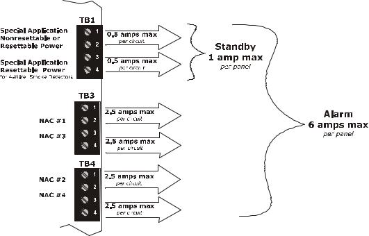
Specifications |
Product Description |
EIA-485 (TERM) or EIA-232 (ACS) - TB8
EIA-485 Terminal Mode annunciator connections: Terminal 1 (Out +), 2 (In +), 3 (Out -), 4 (In -)
EIA-232 PC/Printer applications connections: Terminal 1 (Transmit), 2 (Receive), 3 (Ground)
EIA-485 (ACS) - TB9
ACS annunciator connector, Terminal 1 (+) and Terminal 2 (-), requires ferrite bead
1.2.1 Current Availability
The following figure illustrates the maximum current that is possible for each panel circuit and the total current available from the FACP with optional second transformer.
Note: If NACs are configured as two Style Z (Class A) circuits, each circuit can handle 2.5 amps maximum.
Refer to the battery calculations section for additional information.
Figure 1.1 Current Availability
6.0 amps with optional second XRM-24(E) transformer.
3.0 amps max. with only standard transformer installed.
owerdist9200ud.cdr
MS-9200UDLS PN 52750:A 11/04/05 |
15 |
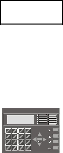
Product Description
1.3 Controls and Indicators
LCD Display
The FACP uses an 80-character (4 lines X 20 characters) high viewing angle LCD display. The display includes a long life LED
backlight that remains illuminated. If AC power is lost and the system is
not in alarm, the LED backlight will turn off to conserve batteries.
LED Indicators
LED indicators are provided to annunciate the following conditions:
•AC Power (green)
•Fire Alarm (red)
•Supervisory (yellow)
•Trouble (yellow)
•Maintenance/presignal (yellow)
•Alarm Silenced signals (yellow)
•Disabled (yellow)
•Battery fault (yellow)
•Ground fault (yellow)
Key Panel
Mounted on the main circuit board, the key panel includes a window for the LCD display and LED indicators as listed above. The key panel, which is visible with the cabinet door closed, has 25 keys, including a 16 key alpha-numeric pad similar to a telephone keypad.
Function keys:
•Acknowledge/Step
•Alarm Silence
•Drill
•Reset (lamp test)
Service/program keys:
•Keys labeled 1 to 9
•* key
•# key
•0 (recall) key
•1st Event key
1  2
2  3
3  1st
1st
|
ABC |
DEF |
EVENT |
4 |
5 |
6 |
CLR |
GHI |
JKL |
MNO |
|
7 |
8 |
9 |
ESC |
PRS |
TUV |
WXY |
|
* |
0 |
# |
MODE |
|
|
|
|
QZ |
|
-/. |
|
RECALL
AC POWER |
MAINTENANCE |
FIRE ALARM |
ALARM |
SILENCED |
|
SUPERVISORY |
DISABLED |
TROUBLE |
BATTERY |
|
GROUND |
ACK/STEP |
|
|
ALARM |
|
SILENCE |
ENTER |
|
|
DRILL |
|
HOLD 2 SEC |
|
RESET |
9600kypd.cdr
• Clear key |
Figure 1.2 Membrane/Display Panel |
•Escape key
•Mode key
•Four cursor keys (up, down, left and right)
•Enter key
Local Piezo Sounder
A piezo sounder provides separate and distinct pulse rates for alarm, trouble and supervisory conditions.
16 |
MS-9200UDLS PN 52750:A 11/04/05 |
Circuits |
Product Description |
1.4 Circuits
Reference
Manual
SLC Communication Loop
One SLC loop is provided standard on the FACP main circuit board. The SLC loop, configurable for NFPA Style 4, 6 or 7, provides communication to addressable detectors, monitor (initiating device) and control (output device) modules. Refer to the SLC Wiring manual for information on wiring devices.
Output Circuits
The following output circuits are available on the FACP:
•Special Application Power
24 VDC Resettable (smoke detector power) output - 0.5 amps maximum 24 VDC Nonresettable or Resettable power output - 0.5 amps maximum
• 24 VDC Battery Charger (up to 18 AH batteries)
NAC (Notification Appliance Circuits)
NACs configurable for four Style Y (Class B) or two Style Z (Class A) using NACKEY card in JP6, are provided with various programmable features.
Relays
One fixed and two fully programmable Form-C dry contact relays are provided. The fixed fail-safe relay monitors system trouble and the two programmable relays are factory default programmed for system alarm and system supervisory. Contacts are rated 2.0 amps @ 30 VDC (resistive) and 0.5 amps @ 30 VAC (resistive). The programmable relays can be programmed for the following operations:
•fire alarm
•trouble
•supervisory
•supervisory auto-resettable
•DACT communication failure
•process monitor
•process monitor auto-resettable
•hazard alert
•medical alert
•AC loss
1.5 Digital Alarm Communicator/Transmitter
Two modular phone jacks allow easy connection to telephone lines. Modular jacks are labeled PH1 for Primary Phone Line and PH2 for Secondary Phone Line. Two telephone line active red LEDs are provided as well as a green Kissoff LED. The integral digital communicator provides the following functions:
•Line Seizure: takes control of the phone lines disconnecting any premises phones
•Off/On Hook: performs on and off-hook status to the phone lines
•Listen for dial tone: 440 Hz tone typical in most networks
•Dialing the Central Station(s) number: default is Touch-Tone®, programmable to rotary
•For tone burst or touchtone type formats: discern proper Ack and Kissoff tone(s). The frequency and time duration of the tone(s) varies with the transmission format. The control panel will adjust accordingly.
•Communicate in the following formats:
12 Tone Burst types: 20 pps
(3+1, 4+1, 4+2, 3+1 Exp., 4+1 Exp., 4+2 Exp.)
3 Touchtone Types
4+1 Ademco Express
4+2 Ademco Express
Ademco Contact ID
MS-9200UDLS PN 52750:A 11/04/05 |
17 |
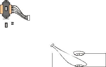
Product Description |
Components |
1.6 Components
See Page
Main Circuit Board
The main circuit board contains the system’s CPU, power supply, other primary components and wiring interface connectors. The 4XTMF option module plugs in and is mounted to the main circuit board.
Cabinet
The MS-9200UDLS backbox provides space for two batteries (up to 18 Amp Hour). Ample knockouts are provided for system wiring. Also available is an optional dress panel (DP-9692), which mounts to the inside of the cabinet (required by ULC for Canadian installations). The dress panel must be installed to meet FM requirements.
Optional
XRM-24(E)
Standard
XRM-24(E)


 9200xfor.cdr
Transformer Assembly
One 100VA transformer is provided standard with the panel (3.6 amps maximum). An optional 100 VA transformer XRM-24 (XRM-24E for the MS-9200UDLSE) is available to provide maximum system and accessory power (6.6 amp total).
Batteries
The MS-9200UDLS cabinet provides space for two batteries (up to 18 Amp Hour). Batteries larger than 18 Amp Hour require an external charger such as the CHG-75 or CHG-120F and a UL listed battery box such as the BB-55F. Batteries must be ordered separately.
Battery Cable P/N 75287
- |
+ |
|
- |
||
+ |
||
|
9200batt.cdr
1.6.1 Intelligent Addressable Detectors: Newer Series
Intelligent, addressable detectors provide information to the control panel on an SLC Signaling Line Circuit (refer to the SLC Wiring Manual for detailed information on device installation, wiring and operation). This allows the control panel to continually process the information to determine the status (alarm, trouble, maintenance or normal) of each detector. Each detector responds to an SLC address that is set in the detector head using built-in rotary decimal switches. The maximum address cannot exceed address 99. Note that a blinking LED on an intelligent detector indicates communication between the detector and the control panel.
These devices (350 Series or newer) can operate in CLIP mode (Classic Loop Interface Protocol) or LiteSpeed mode to provide a quicker response. They are also compatible with older 300 Series devices. If a mix of old and new series devices are installed on the same loop, the FACP must be programmed to operate in CLIP mode. Refer to the SLC Wiring Manual for a list of compatible addressable detectors.
18 |
MS-9200UDLS PN 52750:A 11/04/05 |
Components |
Product Description |
Reference
Manual
1.6.2 Intelligent Addressable Modules: Newer Series
The newer series of Control Modules and Monitor Modules provide an interface between the control panel and conventional notification and initiating devices. Each module can be set to respond to an address with built-in rotary switches. The maximum address cannot exceed address 99. Note that a blinking LED on an addressable module indicates communication between the module and the control panel.
These devices (350 Series or newer) can operate in CLIP mode (Classic Loop Interface Protocol) or LiteSpeed mode to provide a quicker response. They are also compatible with older 300 series devices. If a mix of old and new series devices are installed on the same loop, the FACP must be programmed to operate in CLIP mode. Refer to the SLC Wiring Manual for a list of compatible addressable modules. Refer to the Device Compatibility Document for a list of approved conventional notification and initiating devices.
1.6.3 300 Series Intelligent Addressable Devices
Fire-Lite’s 300 Series Intelligent Addressable Devices are fully compatible with the MS-9200UDLS FACP. The address of 300 Series devices cannot be set above 99. Refer to the SLC Wiring Manual for a list of compatible addressable devices.
1.6.4 Addressable Device Accessories
End-of-Line Resistor Assembly
The End-of-Line resistors are included with each module. Refer to the specific module documentation for specific information.
Power Supervision Relay
The UL listed End-of-Line power supervision relay is used to supervise the power to 4- wire smoke detectors and notification appliances.
N-ELR Mounting Plate
The N-ELR is a single End-of-Line resistor plate which is required for use in Canada. An ELR, which is supplied with each module and fire alarm control panel, is mounted to the ELR plate. Resistors mounted to the N-ELR plate can be used for the supervision of a monitor and control module circuit.
MS-9200UDLS PN 52750:A 11/04/05 |
19 |
Product Description |
Optional Modules |
1.7 Optional Modules
The MS-9200UDLS main circuit board includes option module connectors for the following module:
4XTMF Transmitter Module
The 4XTMF provides a supervised output for local energy municipal box transmitter, alarm and trouble reverse polarity. It includes a disable switch and disable trouble LED. A jumper on the module is used to select an option which allows the reverse polarity circuit to open with a system trouble condition if no alarm condition exists. The module plugs into connectors J5 and J6 which are located near the right edge the main circuit board. When the 4XTMF module is installed, Jumper JP3, on the main circuit board, must be cut to allow supervision of the module.
1.8 Accessories
1.8.1 PK-CD Programming Utility
The PK-CD Programming Utility can be used to program an MS-9200UDLS directly from most IBM compatible computers, including laptops and portables, equipped with a serial port. MS-9200UDLS program files can also be created and stored on the PC and then downloaded to the control panel. The PK-CD Kit includes the MS9200UDLS Windows-based Programming Utility software on CD-ROM with on-line help file. A serial cable (P/N: PRT/PK-CABLE), which must be purchased separately, is required for connection of the PC to the RS-232 (PC/Printer) terminals at TB8 of the MS-9200UDLS main circuit board. Refer to the illustration on page 10 and the section titled "Printer/PC" on page 40, for the location and connections to this terminal.
1.8.2 Dress Panel
An optional dress panel DP-9692 is available for the MS-9200UDLS (required by ULC for Canadian installations). The dress panel restricts access to the system wiring while allowing access to the key panel. A ground strap must be connected between the stud on the inside of the dress panel and the ground stud in the backbox. The dress panel must be installed to meet FM requirements.
dp9200udls.cdr
20 |
MS-9200UDLS PN 52750:A 11/04/05 |
Accessories |
Product Description |
Reference
Manual
1.8.3 Battery Box
BB-26
The BB-26 battery box may be used to house up to two 26 AH batteries and the CHG-75 Battery Charger. The battery box, which is red and is provided with knockouts, was designed specifically to compliment mounting below the FACP.
BB-55F
The BB-55F battery box may be used to house two 25 AH batteries, two 60 AH batteries or one 100 AH battery. When the CHG-120F is mounted in the BB-55F, two 25 AH or one 60 AH battery may also be housed in the battery box.
1.8.4Battery Charger
1.8.4.1CHG-75 Battery Charger
The CHG-75 is capable of charging up to 75 AH lead-acid batteries with the MS9200UDLS FACP. The FACP battery charger must be disabled, by removing jumper JP5, when using the CHG-75. The charger and up to 26 AH batteries can be housed in the BB-26 battery box. Larger batteries and the charger can be housed in the BB-55F battery box which can be mounted up to 20 feet away from the control panel. Refer to the CHG-75 Manual for additional information.
1.8.4.2 CHG-120F Battery Charger
The CHG-120F is capable of charging up to 120 AH lead-acid batteries with the MS-9200UDLS FACP. The FACP battery charger must be disabled, by removing jumper JP5, when using the CHG-120F. The batteries and charger can be housed in the BB-55F battery box which can be mounted up to 20 feet away from the control panel. Note that when using the BB-55F for housing the charger and batteries greater than 25AH, multiple BB-55Fs are required. Refer to the CHG-120F Manual for additional information.
MS-9200UDLS PN 52750:A 11/04/05 |
21 |
Product Description |
Accessories |
Reference
Manual
1.8.5 Annunciators
ACS Series LED Zone Type Annunciators
The ACS Series Annunciators remotely display alarm and trouble status as well as system status. In addition, they can provide remote Acknowledge, Silence, Reset and Drill functions. For more detailed information, refer to the appropriate annunciator manual. Following is a list of annunciators which can be used with the MS9200UDLS.
•ACM-16ATF* Annunciator Control Module annunciates 16 zones with 16 red alarm LEDs and 16 yellow trouble LEDs. In addition, it has a System Trouble LED, an On Line/Power LED and a local piezo sounder. It also has switches for FACP Acknowledge, Silence, Reset and Drill. It has rotary address switches and will accept up to three AEM-16ATF Expanders. In Canada, this module must be used to annunciate the fire alarm input points/zones only.
•AEM-16ATF Annunciator Expander Module annunciates 16 zones with 16 red alarm LEDs and 16 yellow trouble LEDs
•AFM-16ATF* Annunciator Fixed Module annunciates 16 zones with 16 red alarm LEDs and 16 yellow trouble LEDs. In addition, it has a System Trouble LED, an On Line/Power LED and a local piezo sounder. It also has switches for FACP Acknowledge, Silence, Reset and Drill. It is fixed at address ‘1.’ In Canada, this module must be used to annunciate the fire alarm input points/zones only.
•ACM-32AF* Annunciator Control Module annunciates 32 alarm zones with 32 red LEDs. In addition, it has a System Trouble LED, an On Line/Power LED and a local piezo sounder. It also has a switch for local piezo silence. It has rotary address switches and will accept one AEM-32AF Expander. In Canada, this module must be used to annunciate the fire alarm input points/zones only.
•AEM-32AF Annunciator Expander Module annunciates 32 alarm zones with 32 red LEDs
•AFM-16AF* Annunciator Fixed Module annunciates 16 alarm zones with 16 red alarm LEDs. In addition, it has a System Trouble LED, an On Line/Power LED and a local piezo sounder. It also has a switch for local piezo silence. It is fixed at address ‘1.’ In Canada, this module must be used to annunciate the fire alarm input points/zones only.
•AFM-32AF* Annunciator Fixed Module annunciates 32 alarm zones with 32 red LEDs. In Canada, this module must be used to annunciate the fire alarm input points/zones only.
*In Canada, the color red must be used to indicate active alarm inputs. Yellow indicates supervisory, burglary or trouble signals. Green indicates the presence of power, or an activated output.
22 |
MS-9200UDLS PN 52750:A 11/04/05 |
Getting Started
Reference
Manual
Reference
Manual
Product Description
LCD-80F Remote Fire Annunciator
The LCD-80F annunciator is a compact 80-character backlit LCD remote fire annunciator that is capable of displaying English language text. It mimics the display on the control panel and will annunciate device type, point alarm, trouble or supervisory condition, zone assignment plus any custom alpha labels programmed into the FACP. The annunciator also provides system status LEDs to display AC Power, Alarm, Trouble, Supervisory and Alarm Silenced conditions. Additionally, the LCD80F is capable of remotely performing critical system functions such as Acknowledge, Silence, Reset and Drill.
Communications between the control panel and the annunciator is accomplished over a serial interface employing the EIA-485 communication standard. Up to 32 LCD-80F annunciators may be connected to the EIA-485 circuit. The annunciators may be powered from the host FACP or a remote UL listed filtered power supply such as the FCPS Series. For more detailed information, refer to the LCD-80F manual.
LDM Series Lamp Driver Modules (Graphic Annunciator)
The LDM Series Lamp Driver Modules, which consist of the LDM-32F master and LDM-E32F expander modules, are used to provide an interface to a custom graphic LED annunciator. The master module provides power and control for a maximum of three expander modules. The LDM-32F and LDM-E32F have output connectors which are used to drive lamps or LEDs and input connectors which are used for remote switch functions. Refer to the LDM Series Lamp Driver Modules manual for a complete description.
1.9 Getting Started
The following is a brief summary of the minimal steps involved in bringing an MS9200UDLS on-line:
•Install Backbox and Main Circuit Board (refer to "Mounting Backbox" on page 27)
•Address and Install Intelligent Devices (refer to the SLC Wiring Manual)
•Enter Autoprogramming (refer to "Autoprogram" on page 47)
•Resolve Programming Conflicts
•Go to Point Program to Enter Specific Data (refer to "Point Program" on page 48). Use the right and left arrow keys to navigate between devices.
MS-9200UDLS PN 52750:A 11/04/05 |
23 |
Product Description |
Telephone Requirements and Warnings |
1.10 Telephone Requirements and Warnings
1.10.1Telephone Circuitry
Ringer Equivalence Number (REN) = 0.0B AC Impedance: 10.0 Mega Ohm Complies with FCC Part 68
Mates with RJ31X Male Connector
Supervision Threshold: less than 4.0 volts for 2 minutes
The REN is used to determine the quantity of devices which may be connected to the telephone line. Excessive RENs on the telephone line may result in the devices not ringing in response to an incoming call. In most, but not all areas, the sum of the RENs should not exceed five (5.0). To be certain of the number of devices that may be connected to the line as determined by the total RENs, contact the telephone company to determine the maximum REN for the calling area.
1.10.2Digital Communicator
Before connecting the control panel to the public switched telephone network, the installation of two RJ31X jacks is necessary. If trouble is experienced with this equipment, for repair or warranty information, please contact:
Manufacturer: Fire•Lite Alarms, Inc. One Fire-Lite Place Northford, CT 06472 (203) 484-7161
Product Model Number: MS-9200UDLS
FCC Registration Number: US:1W6AL00B9200UD
Ringer Equivalence: 0.0B
Note: This equipment complies with Part 68 of the FCC rules and the requirements adopted by the ACTA. On the inside of the FACP door is a label that contains, among other information, a product identifier in the format US:AAAEQ##TXXXX. If requested, this number must be provided to the telephone company.
Alarm dialing equipment must be able to seize the telephone line and place a call in an emergency situation. It must be able to do this even if other equipment (telephone, answering system, computer modem, etc.) already has the telephone line in use. To do so, alarm dialing equipment must be connected to a properly installed RJ31X jack that is electrically in series with and ahead of all other equipment attached to the same telephone line. If there are any questions concerning these instructions, consult the telephone company or a qualified installer about installing the RJ31X jack and alarm dialing equipment. Refer to "Digital Communicator" on page 36 for an illustration of the proper installation of this equipment.
Important! The DACT must not be used to dial a phone number that is call-forwarded per requirements of UL 864 9th Edition.
24 |
MS-9200UDLS PN 52750:A 11/04/05 |
Telephone Requirements and Warnings |
Product Description |
1.10.3Telephone Company Rights and Warnings
The telephone company, under certain circumstances, may temporarily discontinue services and/or make changes in its facilities, services, equipment or procedures which may affect the operation of this control panel. However, the telephone company is required to give advance notice of such changes or interruptions.
If the control panel causes harm to the telephone network, the telephone company reserves the right to temporarily discontinue service. Advance notification will be provided except in cases when advance notice is not practical. In such cases, notification will be provided as soon as possible. The opportunity will be given to correct any problems and to file a complaint with the FCC if you believe it is necessary.
DO NOT CONNECT THIS PRODUCT TO COIN TELEPHONE, GROUND START, OR PARTY LINE SERVICES.
When the control panel activates, premise phones will be disconnected.
Two separate phone lines are required. Do not connect both telephone interfaces to the same telephone line.
The control panel must be connected to the public switched telephone network upstream (as first device) of any private telephone system at the protected premises.
A plug and jack used to connect this equipment to the premises wiring and telephone network must comply with the applicable FCC Part 68 rules and requirements adopted by ACTA. This equipment is designed to be connected to the telephone network or premises wiring using a compliant RJ31X male modular plug and compatible modular jack that is also compliant.
MS-9200UDLS PN 52750:A 11/04/05 |
25 |
Product Description |
Telephone Requirements and Warnings |
1.10.4For Canadian Applications
The following is excerpted from CP-01 Issue 5:
NOTICE: The Industry Canada (IC) label identifies certified equipment. This certification means that the equipment meets certain telecommunications network protective, operational and safety requirements as prescribed in the appropriate Terminal Equipment Technical Requirements document(s). The Department does not guarantee the equipment will operate to the users’s satisfaction.
Before installing this equipment, users should ensure that it is permissible to be connected to the facilities of the local telecommunications company. The equipment must also be installed using an acceptable method of connection. The customer should be aware that compliance with the above conditions may not prevent degradation of service in some situations.
Repairs to certified equipment should be made by an authorized Canadian maintenance facility designated by the supplier. Any repairs or alterations made by the user to this equipment, or equipment malfunctions, may give the telecommunications company cause to request the user to disconnect the equipment.
Users should ensure, for their own protection, that the electrical ground connections of the power utility, telephone lines and internal metallic water pipe system, if present, are connected together. This precaution may be particularly important in rural areas.
CAUTION
Users should not attempt to make such connections themselves, but should contact the appropriate electric inspections authority, or electrician.
“The Ringer Equivalence Number (REN) assigned to each terminal device provides an indication of the maximum number of terminals allowed to be connected to a telephone interface. the termination of an interface may consist of any combination of devices subject only to the requirement that the sum of the REN of all devices does not exceed 5.”
DOC Compliance - “This digital apparatus does not exceed the Class A limits for radio noise emissions from digital apparatus set out in the Radio Interference Regulations of the Canadian Department of Communications.”
Representative: NOTIFIER/FIRE•LITE, CANADA
24 Viceroy Road
Concord, Ontario L4K2L9
Phone: (905) 660-7210
FAX: (905) 660-7204
IC Certificate Number:
Ringer Equivalence Number (REN): 1.3B
Load Number: 2
26 |
MS-9200UDLS PN 52750:A 11/04/05 |
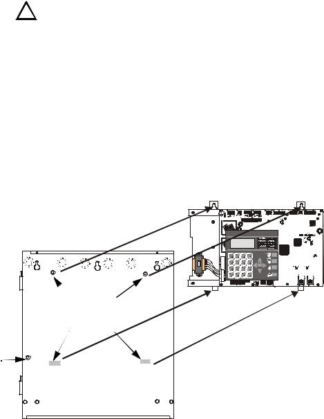
Mounting Backbox
SECTION 2
Installation
Installation
The cabinet may be either semi-flush or surface mounted. The cabinet mounts using two key slots and two 0.250” (6.35 mm) diameter holes located in the backbox. The key slots are located at the top of the backbox and the two securing holes at the bottom.
Carefully unpack the system and check for shipping damage. Mount the cabinet in a clean, dry, vibration-free area where extreme temperatures are not encountered. The area should be readily accessible with sufficient room to easily install and maintain the panel. Locate the top of the cabinet approximately 5 feet (1.5 m) above the floor with the hinge mounting on the left. Determine the number of conductors required for the devices to be installed. Sufficient knockouts are provided for wiring convenience. Select the appropriate knockout(s) and pull the conductors into the box. All wiring should be in accordance with the National and/or Local codes for fire alarm systems.
2.1 Mounting Backbox
The circuit board contains static-sensitive components. Always ground yourself with a
grounding stud
!proper wrist strap before handling any boards so that static charges are removed from the body. Use static suppressive packaging to protect electronic assemblies.
To prevent damage to the circuit board and to facilitate backbox mounting, the chassis with main circuit board and transformer can be easily removed. Loosen the tow 3/8” nuts securing the top flanges of the chassis, then slide the chassis up to free it from the lower tabs. Place the chassis assembly in a safe location until it can be reinstalled in the backbox.
Mark and predrill hole in the wall for the center top keyhole mounting bolt using the dimensions illustrated in Figure 2.3 on page 29
See Page
Install center top fastener in the wall with the screw head protrudingPlace backbox over the top screw, level and secure
Mark and drill the left and right upper and lower mounting holes
Note: outer holes (closest to sidewall) are used for 16” O.C. stud mountingInstall remaining fasteners and tighten
Main Circuit Board on chassis
 mounting studs
mounting slots |
92udchassisinbox.cdr |
|
Backbox
Figure 2.1 MS-9200UDLS Chassis Removal
MS-9200UDLS PN 52750:A 11/04/05 |
27 |
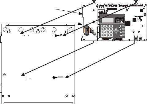
Installation |
Mounting Transformer |
2.2 Mounting Transformer
One XRM-24(E) transformer is supplied standard with the control panel. An optional second XRM-24(E) transformer can be ordered and installed to provide maximum system power. Install the transformers in the locations indicated in the following illustration.
1.When the location is dry and free of construction dust, install the chassis/ transformer/circuit board assembly.
2.Mount the chassis to the backbox by aligning the two mounting tabs with the slots in the backbox, then position the two mounting hole tabs over the studs with nuts located in the upper portion of the backbox.
3.Slide the tabs located on the bottom of the chassis into the mounting slots in the backbox by pressing the chassis down.
4.Secure the chassis to the backbox by tightening the two mounting nuts (#10-32) at the top, and to ensure proper grounding, use a 3/8” nut driver or socket.
5.If the main circuit board is not already attached to the chassis, install it by positioning the ten mounting holes over the studs on the chassis and secure with the supplied screws.
6.Connect the Standard XRM-24 Transformer plug to Transformer 1 Connector J10 on the FACP main circuit board
7.Connect the Optional XRM-24 Transformer plug to Transformer 2 Connector J11 on the FACP main circuit board.
8.Complete the installation as detailed in the following sections.
Optional XRM-24 Transformer
Standard XRM-24 Transformer

 Mounting Studs

 Mounting Slot
Figure 2.2 MS-9200UDLS Main Board/Chassis Installation
28 |
MS-9200UDLS PN 52750:A 11/04/05 |

Mounting Transformer |
Installation |
Semi-Flush Mounting
Do not recess box more than 3.875” into wall to avoid covering venting  holes on top of box.
9050udencl.cdr
Figure 2.3 MS-9200UDLS Cabinet Mounting
MS-9200UDLS PN 52750:A 11/04/05 |
29 |
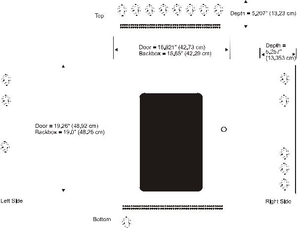
Installation |
|
|
|
|
|
|
|
|
|
Mounting Transformer |
||||||||||||||||||
|
|
|
|
|
|
|
|
|
|
|
|
|
|
|
|
|
|
|
|
|
|
|
|
|
|
|
|
|
|
|
|
|
|
|
|
|
|
|
|
|
|
|
|
|
|
|
|
|
|
|
|
|
|
|
|
|
|
|
|
|
|
|
|
|
|
|
|
|
|
|
|
|
|
|
|
|
|
|
|
|
|
|
|
|
|
|
|
|
|
|
|
|
|
|
|
|
|
|
|
|
|
|
|
|
|
|
|
|
|
|
|
|
|
|
|
|
|
|
|
|
|
|
|
|
|
|
|
|
|
|
|
|
|
|
|
|
|
|
|
|
|
|
|
|
|
|
|
|
|
|
|
|
|
|
|
|
|
|
|
|
|
|
|
|
|
|
|
|
|
|
|
|
|
|
|
|
|
|
|
|
|
|
|
|
|
|
|
|
|
|
|
|
|
|
|
|
|
|
|
|
|
|
|
|
|
|
|
|
|
|
|
|
|
|
|
|
|
|
|
|
|
|
|
|
|
|
|
|
|
|
|
|
|
|
|
|
|
|
|
|
|
|
|
|
|
|
|
|
|
|
|
|
|
|
|
|
|
|
|
|
|
|
|
|
|
|
|
|
|
|
|
|
|
|
|
|
|
|
|
|
|
|
|
|
|
|
|
|
|
|
|
|
|
|
|
|
|
|
|
|
|
|
|
|
|
|
|
|
|
|
|
|
|
|
|
|
|
|
|
|
|
|
|
|
|
|
|
|
|
|
|
|
|
|
|
|
|
|
|
|
|
|
|
|
|
|
|
|
|
|
|
|
|
|
|
|
|
|
|
|
|
|
|
|
|
|
|
|
|
|
|
|
|
|
|
|
|
|
|
|
|
|
|
|
|
|
|
|
|
|
|
|
|
|
|
|
|
|
|
|
|
|
|
|
|
|
|
|
|
|
|
|
|
|
|
|
|
|
|
|
|
|
|
|
|
|
|
|
|
|
|
|
|
|
|
|
|
|
|
|
|
|
|
|
|
|
|
|
|
|
|
|
|
|
|
|
|
|
|
|
|
|
|
|
|
|
|
|
|
|
|
|
|
|
|
|
|
|
|
|
|
|
|
|
|
|
|
|
|
|
|
|
|
|
|
|
|
|
|
|
|
|
|
|
|
|
|
|
|
|
|
|
|
|
|
|
|
|
|
|
|
|
|
|
|
|
|
|
|
|
|
|
|
|
|
|
|
|
|
|
|
|
|
|
|
|
|
|
|
|
|
|
|
|
|
|
|
|
|
|
|
|
|
|
|
|
|
|
|
|
|
|
|
|
|
|
|
|
|
|
|
|
|
|
|
|
|
|
|
|
|
|
|
|
|
|
|
|
|
|
|
|
|
|
|
|
|
|
|
|
|
|
|
|
|
|
|
|
|
|
|
|
|
|
|
|
|
|
|
|
|
|
|
|
|
|
|
|
|
|
|
|
|
|
|
|
|
|
|
|
|
|
|
|
|
|
|
|
|
|
|
|
|
|
|
|
|
|
|
|
|
|
|
|
|
|
|
|
|
|
|
|
|
|
|
|
|
|
|
|
|
|
|
|
|
|
|
|
|
|
|
|
|
|
|
|
|
|
|
|
|
|
|
|
|
|
|
|
|
|
|
|
|
|
|
|
|
|
|
|
|
|
|
|
|
|
|
|
|
|
|
|
|
|
|
|
|
|
|
|
|
|
|
9050udcab.cdr
Figure 2.4 MS-9200UDLS Cabinet Dimensions
30 |
MS-9200UDLS PN 52750:A 11/04/05 |
 Loading...