


HONEYWELL
MicroniK 200 |
R7426A,B,C |
TEMPERATURE CONTROLLER |
|
WITH AND WITHOUT REAL-TIME CLOCK |
|
|
INSTALLATION & START-UP INSTRUCTIONS |
Fig. 1. Temperature Controller |
|
Contents |
|
General................................................................................ |
1 |
Before Installation Note ....................................................... |
1 |
Mounting.............................................................................. |
1 |
Wiring .................................................................................. |
2 |
Power Supply and Grounding.............................................. |
2 |
Configuration and Control Parameters ................................ |
3 |
Configuration Settings ......................................................... |
6 |
Parameter Settings and Adjustment .................................... |
8 |
Operating Overview............................................................ |
11 |
Notes (with RTC, only)....................................................... |
19 |
GENERAL
This document provides instructions and procedures for installing and starting up the Micronik 200 R7426A,B,C controllers. No special tools are required for mounting and installation. The user interface and liquid-crystal display allow accurate and easy parameter setting and output adjustment.
BEFORE INSTALLATION NOTE
•Visually inspect equipment for shipping damage. Report any damage to the appropriate Honeywell representative.
•Refer to job drawings for specific installation information and mounting location.
•Verify the controllers will be adequately separated from the main power supply, relays, or other equipment which can possibly generate electromagnetic interference.
•Verify that the ambient temperature and the humidity at the controllers will not exceed 0...50°C (32...122°F) and 5 to 95% rh.
•Use shielded wiring in areas with high EMI.
•All wiring should be separated from power lines by at least 150 mm (6’’).
•Do not install controllers near frequency converters or other high-frequency sources.
MOUNTING
The controllers can be mounted in an electric cabinet or other suitable enclosure. They are suitable for back panel, DIN rail, wall, or front panel mounting. The corresponding mounting sequence, as well as dimensions and panel cut-out, are illustrated in the mounting instruction sheet EN1B-0202GE51 supplied with the controllers.
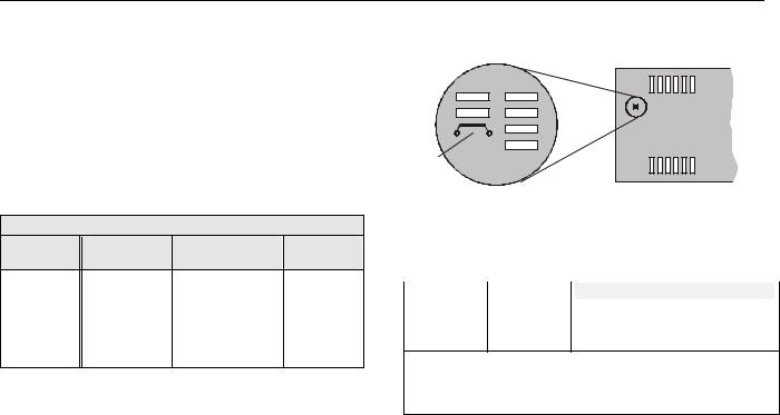
If the compensation sensor signal (T3) is received from another controller (parallel connection of compensation sensor inputs), the jumper W303 has to be cut before mounting the controller (see Fig. 2). This disconnects the sensor from the internal power supply.
Copyright © 2007 Honeywell GmbH All Rights Reserved |
|
|
|
|
|
EN1B-0203GE51 R0507C |
|
|
|
|
|
|
|
R7426A,B,C TEMPERATURE CONTROLLER WITH AND WITHOUT REAL-TIME CLOCK
WIRING
Screwless type, spring loaded terminals are provided on the controllers for panel and field wiring. These terminals are suitable for solid conductors as well as tinned or with multicore cable end, stranded wires up to 1.5 mm2. To make a termination, push the wire into the terminal or insert a small screwdriver from the front of the controller into the spring-release hole and insert the wire. Check for proper connection by short pull on the wire.
Table 1. Terminal Connection
controller to CPA/SPA potentiometer
R7426A,B,C T7412B1016 T7412B1057/1008 T7412B1024 T7412C1030/1006 T7412B1040
terminal 2 |
|
terminal 4 |
terminal 4 |
terminal 4 |
terminal 4 |
|
terminal 5 |
terminal 6 |
terminal 5+6 |
R7426A,B,C |
|
43193982-001 |
- |
- |
terminal 2 |
|
terminal 1 |
- |
- |
terminal 4 |
|
terminal 3 |
- |
- |
Table 2. Wire Dimensions
|
wiring run |
|
type of |
|
length max. |
||
|
|
wires |
|
1.0 mm2 |
|
1.5 mm2 |
|
|
|
|
|
|
|||
|
from controller to all |
|
local |
|
100 m |
|
150 m |
|
input and output |
|
standard |
|
|
||
|
devices |
|
|
|
|
|
|
|
|
|
|
|
|
|
|
W303
Fig. 2. Parallel Connection of Compensation Sensor T3
|
Table 3. Jumper States |
|
jumper1) |
state |
description |
W303 |
closed |
T3 supplied by this controller |
open |
T3 supplied from another |
|
|
controller |
|
|
|
|
1) Default jumper position = closed. Cut (open) jumper W303 only if the T3 input is fed from another controller (parallel connection, max. six devices). This disconnects the T3 input from the internal power supply
Wiring should be done only according to the actual job wiring diagrams or wiring diagrams shown in the mounting instruction sheet EN1B-0202GE51. The wiring to the CPA/SPA potentiometers is described in Table 1. All wiring must conform to applicable codes, ordinances, and regulations. The maximum allowed wiring length per wire size are shown in Table 2.
POWER SUPPLY AND GROUNDING
1.Refer to job drawings and verify correct supply voltage to transformer (230 Vac) and controller (24 Vac).
2.Connect line power conductors to transformer primary. Line power must be supplied from a breaker panel with dedicated controller circuit. Do not turn the line power on until all wiring has been checked against job drawings.
3.Connect transformers 24 Vac secondary to the controller terminals 18 and 19. Connect one conductor to terminal marked 24 V and the other to terminal marked 24 V . If controllers are interconnected all terminals 19 must be connected to the same potential 24 V level.
4.Do not connect the secondary side of the transformer to the installation ground.
EN1B-0203GE51 R0507C |
2 |

R7426A,B,C TEMPERATURE CONTROLLER WITH AND WITHOUT REAL-TIME CLOCK
CONFIGURATION AND CONTROL PARAMETERS
The controllers R7426A,B,C include two groups of settings*) (I and II) for control and configuration parameters that are automatically selected during programming. For parameter Ctrltyp = Lo, setting I is selected, and for parameter Ctrltyp = Hi1/Hi2, setting II is selected.
config. par. |
|
|
description |
|
default |
R7426 |
actual |
|||||
no. |
name |
|
|
|
setting |
A |
B |
C |
value |
|||
|
|
|
|
|
|
|||||||
C.01 |
DIR/REVY1 |
Selects the output action of Y1 to adapt the valve or damper direction |
|
Dir |
|
|
x |
|
||||
C.02 |
DIR/REVY3 |
Selects the output action of Y3 to adapt the valve or damper direction |
|
Dir |
|
|
x |
|
||||
C.03 |
DIR/REVY2 |
Selects the output action of Y2 to adapt the valve or damper direction |
|
Dir |
|
|
x |
|
||||
|
|
Dir |
Direct acting output signal |
|
|
|
|
|
|
|
|
|
|
|
Rev |
Reverse acting output signal |
|
|
|
|
|
|
|
|
|
C.04 |
Ctrltyp1) |
Control |
type selects the setpoint operating range and default parameter |
|
Lo |
x |
x |
x |
|
|||
|
|
setting I or II. |
|
|
|
|
for I |
|
|
|
|
|
|
|
set- |
operating range |
|
setting*) |
|
|
|
|
|
||
|
|
pt. |
|
|
|
|
|
|
|
|
|
|
|
|
Lo |
0...50°C |
for ventilation systems (factory preset) |
|
I |
|
|
|
|
|
|
|
|
Hi1 |
0...130°C |
for heating systems |
|
II |
|
|
|
|
|
|
|
|
Hi2 |
0...130°C |
with pump ON/OFF operation |
|
II |
|
|
|
|
|
|
C.05 |
CPATYP |
Selects |
the Control Point /SetPoint Adjustment type. |
|
|
0 |
x |
x |
x |
|
||
|
|
CPA |
potentio- |
CPA/SPA |
sensor / remote setpoint unit type |
|
|
|
|
|
||
|
|
TYP |
meter range |
range |
numbers |
|
|
|
|
|
|
|
|
|
0 |
internal |
CPA: ±5K |
internal |
|
|
|
|
|
|
|
|
|
1 |
953...1053Ω |
CPA: ±5K |
T7412B1016 (Pt 1000) |
|
|
|
|
|
|
|
|
|
2 |
100kΩ...0Ω |
CPA: ±5K |
T7412B1057 / T7412C1030 (Pt 1000) |
|
|
|
|
|
||
|
|
T7412B1008 / T7412C1006 (NTC 20kΩ) |
|
|
|
|
|
|||||
|
|
|
|
|
43193982-001 |
|
|
|
|
|
|
|
|
|
3 |
10...20kΩ |
SPA: |
T7412B1024 (BALCO 500) |
|
|
|
|
|
|
|
|
|
15 ... 30°C |
T7412B1040 (Pt 1000) |
|
|
|
|
|
|
|||
|
|
4 |
0...10kΩ |
CPA: ±5K |
HCW 23 (setpt wheel printed with +/- 5 K) |
|
|
|
|
|
||
|
|
5 |
0...100kΩ |
SPA: 15...30°C |
43193982-001 |
|
|
|
|
|
|
|
|
|
6 |
0...100kΩ |
SPA: 0...50°C |
43193982-001 |
|
|
|
|
|
|
|
|
|
or 0...130°C |
|
|
|
|
|
|
|
|||
C.06 |
YRange |
Selects |
the output |
control range for |
all outputs (Y1, Y2, and Y3) |
|
1 |
|
|
x |
|
|
|
|
0 |
2 ... 10 Vdc |
|
|
|
|
|
|
|
|
|
|
|
1 |
0 ... 10 Vdc |
|
|
|
|
|
|
|
|
|
C.07 |
Startup |
Enables the start-up routine |
|
|
|
OFF |
|
x |
x |
|
||
|
|
OFF |
Disabled |
|
|
|
|
|
|
|
|
|
|
|
ON |
Enabled |
|
|
|
|
|
|
|
|
|
C.08 |
Y1Mode |
Y1 output mode selects an individual output function for Y1 |
|
4 |
x |
x |
|
|
||||
C.09 |
Y3Mode |
Y3 output mode selects an individual output function for Y3 |
|
4 |
|
x |
|
|
||||
C.10 |
Y2Mode |
Y2 output mode selects an individual output function for Y2 |
|
4 |
|
x |
|
|
||||
|
|
0 |
Synchronous / floating |
|
|
|
|
|
|
|
|
|
|
|
1 |
2 stage ON/OFF |
|
|
|
|
|
|
|
|
|
|
|
2 |
3 stage binary coded ON/OFF |
|
|
|
|
|
|
|||
|
|
3 |
Pulse-width modulation |
|
|
|
|
|
|
|
|
|
|
|
4 |
Unconfigured |
|
|
|
|
|
|
|
|
|
C.11 |
YMode |
Selects |
the output mode for sequence operation or multistage ON/OFF func. |
0 |
|
x |
x |
|
||||
|
|
0 |
Damper, cooling and heating (Y1,Y2, Y3) |
|
|
|
|
|||||
|
|
1 |
Sequence control for heating or cooling (Y1,Y2, Y3); |
|
|
|
x |
x |
|
|||
|
|
or 6-stage ON/OFF |
|
|
|
|
|
x |
|
|
||
|
|
|
|
|
|
|
|
|
|
|||
|
|
2 |
Sequence control for heating (Y1, Y3) and cooling (Y2); |
|
|
|
x |
x |
|
|||
|
|
or 4-stage ON/OFF for heating (Y1, Y3), and cooling (Y2) |
|
|
|
x |
|
|
||||
|
|
|
|
|
|
|
|
|||||
|
|
3 |
Sequence control for cooling (Y1, Y3) and heating (Y2); |
|
|
|
x |
x |
|
|||
|
|
or 4-stage ON/OFF for cooling (Y1, Y3), and heating (Y2) |
|
|
|
x |
|
|
||||
|
|
|
|
|
|
|
|
|||||
|
|
4 |
Two-position damper control (Y1), heating (Y3) and cooling (Y2) |
|
|
|
x |
x |
|
|||
|
|
5 |
15-stage binary coded ON/OFF for heating (Y1, Y3), and cooling (Y2) |
|
|
x |
|
|
||||
|
|
|
|
Table 4. Configuration parameters R7426A,B,C |
|
|
|
|
|
|
||
3 |
EN1B-0203GE51 R0507C |

R7426A,B,C TEMPERATURE CONTROLLER WITH AND WITHOUT REAL-TIME CLOCK
|
config. par. |
|
|
description |
|
|
default |
|
|
R7426 |
|
actual |
|
||||||||
|
|
|
|
|
|
|
|
|
setting |
|
|
|
|
|
|
|
|
|
|||
|
no. |
|
|
name |
|
|
|
|
|
|
A |
|
B |
|
C |
|
value |
|
|||
|
|
|
|
|
|
|
|
|
I / II |
|
|
|
|
|
|
||||||
|
|
|
|
|
|
|
|
|
|
|
|
|
|
|
|
||||||
|
C.12 |
T2ext |
Enable / Disables the T1 sensor input to be used for both T1 and T2 inputs. |
0 |
|
|
x |
x |
x |
|
|
||||||||||
|
|
|
|
|
|
0 |
T2 installed |
|
|
|
|
|
|
|
|
|
|
|
|
|
|
|
|
|
|
|
|
1 |
T1 signal used for T2 |
|
|
|
|
|
|
|
|
|
|
|
|
|
|
|
C.13 |
LimTyp |
Limitation type determines whether the limit function is low or high. |
0 / 1 |
|
|
x |
x |
x |
|
|
||||||||||
|
|
|
|
|
|
0 |
Low limit |
|
|
|
|
|
|
|
|
|
|
|
|
|
|
|
|
|
|
|
|
1 |
High limit |
|
|
|
|
|
|
|
|
|
|
|
|
|
|
|
C.14 |
|
Senstyp |
Sensor type determines automatic detection or manual selection of NTC |
0 |
|
|
x |
x |
x |
|
|
|||||||||
|
|
|
|
|
|
sensors. |
|
|
|
|
|
|
|
|
|
|
|
|
|
|
|
|
|
|
|
|
|
0 |
Auto detection |
|
|
|
|
|
|
|
|
|
|
|
|
|
|
|
|
|
|
|
|
1 |
NTC sensor type |
|
|
|
|
|
|
|
|
|
|
|
|
|
|
|
C.15 |
|
Y1CTRF |
Controls the action of Y1 or activates the occupancy input for summer/winter |
0 / 1 |
|
|
x |
x |
x |
|
|
|||||||||
|
|
|
|
|
|
changeover. |
|
|
|
|
|
|
|
|
|
|
|
|
|
|
|
|
|
|
|
|
|
R7426A |
R7426B,C |
|
|
|
|
|
|
|
|
|
|
|
|
||
|
|
|
|
|
|
0 |
cooling |
0 |
mixed air damper |
|
|
|
|
|
|
|
|
|
|
|
|
|
|
|
|
|
|
1 |
heating |
1 |
energy recovery |
|
|
|
|
|
|
|
|
|
|
|
|
|
|
|
|
|
|
2 |
summer/winter changeover |
|
|
|
|
|
|
|
|
|
|
|
|
|
|
|
C.16 |
|
AddHour2) |
Adjusts the month for winter/summer time change. |
3 |
|
|
x |
x |
x |
|
|
|||||||||
|
|
|
|
|
|
Min. |
0 (disables winter/summer time change) |
|
(March) |
|
|
|
|
|
|
|
|
|
|||
|
|
|
|
|
|
Max. |
12 |
|
|
|
|
|
|
|
|
|
|
|
|
|
|
|
C.17 |
|
SubHour2) |
Adjusts the month for summer/winter time change. |
10 |
|
|
x |
x |
x |
|
|
|||||||||
|
|
|
|
|
|
Min. |
0 (disables summer/winter time change) |
|
(Oct.) |
|
|
|
|
|
|
|
|
|
|||
|
|
|
|
|
|
Max. |
12 |
|
|
|
|
|
|
|
|
|
|
|
|
|
|
|
C.18 |
|
PSTG_H2) 3) |
Determines the prestart gradient to reach the comfort setpoint for heating. |
|
0 K/min |
|
x |
x |
x |
|
|
|||||||||
|
|
|
|
|
|
Min. |
0 (disabled) |
|
|
|
|
|
|
|
|
|
|
|
|
|
|
|
|
|
|
|
|
Max. |
2 |
|
|
|
|
|
|
|
|
|
|
|
|
|
|
|
C.19 |
|
PSTG_C2) 3) |
Determines the prestart gradient to reach the comfort setpoint for cooling. |
|
0 K/min |
|
x |
x |
x |
|
|
|||||||||
|
|
|
|
|
|
Min. |
0 (disabled) |
|
|
|
|
|
|
|
|
|
|
|
|
|
|
|
|
|
|
|
|
Max. |
2 |
|
|
|
|
|
|
|
|
|
|
|
|
|
|
|
C.20 |
|
tvd2) |
Determines the damper prestart time before scheduled comfort mode |
|
15 min |
|
|
|
x |
x |
|
|
||||||||
|
|
|
|
|
|
Min. |
0 (normal control) |
|
|
|
|
|
|
|
|
|
|
|
|
|
|
|
|
|
|
|
|
Max. |
90 |
|
|
|
|
|
|
|
|
|
|
|
|
|
|
|
C.21 |
Adapt2) |
Optimum Start Self Adaption speed |
|
|
50% |
|
|
x |
x |
x |
|
|
||||||||
|
|
|
|
|
|
Min. |
0 |
|
|
|
|
|
|
|
|
|
|
|
|
|
|
|
|
|
|
|
|
Max. |
100 |
|
|
|
|
|
|
|
|
|
|
|
|
|
|
|
C.22 |
Adr1) |
Sets the serial communication address, used for service or maintenance. |
254 |
|
|
x |
x |
x |
|
|
||||||||||
|
|
|
|
|
|
Min. |
0 |
|
|
|
|
|
|
|
|
|
|
|
|
|
|
|
|
|
|
|
|
Max. |
255 |
|
|
|
|
|
|
|
|
|
|
|
|
|
|
|
C.23 |
|
DefProg |
Initiates the default programming. |
|
|
0 |
|
|
x |
x |
x |
|
|
|||||||
0No Default programming
1Initiates Default programming
1)actual value will not be changed during reset to default parameter
2)on Controllers with Real-Time Clock, only
3)can be overwritten by controller for self-adaption purposes, resolution = 0.01 K/min
For detailed information of configuration parameters see chapter Configuration Settings.
Table 4. Configuration parameters R7426A,B,C (part 2)
EN1B-0203GE51 R0507C |
4 |

R7426A,B,C TEMPERATURE CONTROLLER WITH AND WITHOUT REAL-TIME CLOCK
|
control par. |
description |
setting I / setting II |
|
reso- |
unit |
R7426 |
actual |
|||||||
|
no. |
name |
low |
|
high |
|
def. |
lution |
A |
B |
C |
value |
|||
|
|
|
|||||||||||||
|
|
|
|
|
|
|
|
|
|
|
|
|
|
|
|
P.01 |
W1 |
Main setpoint for input T1 |
0 |
|
50 / |
|
21 |
/ |
0.5 |
°C |
x |
x |
x |
|
|
|
130 |
|
70 |
|
|
||||||||||
|
|
|
|
|
|
|
|
|
|
|
|
|
|
||
P.02 |
Wlim |
Limit setpoint (low or high) for input T2 |
5 / |
|
50 / |
|
16 |
/ |
1 |
°C |
x |
x |
x |
|
|
30 |
|
130 |
|
90 |
|
|
|||||||||
|
|
|
|
|
|
|
|
|
|
|
|
|
|||
|
|
|
|
|
|
|
|
|
|
|
|
|
|
|
|
P.03 |
Wcomp |
Compensation changeover point for input T3 |
-5 |
|
40 |
|
20 |
|
1 |
°C |
x |
x |
x |
|
|
|
|
|
|
|
|
|
|
|
|
|
|
|
|
|
|
P.04 |
Wi |
Winter compensation authority |
-350 |
|
+350 |
|
0 |
|
2 |
% |
x |
x |
x |
|
|
|
|
|
|
|
|
|
|
|
|
|
|
|
|
|
|
P.05 |
Su |
Summer compensation authority |
-100 |
|
+100 |
|
0 |
|
1 |
% |
x |
x |
x |
|
|
|
|
|
|
|
|
|
|
|
|
|
|
|
|
|
|
P.06 |
Wcas |
Submaster or cascade setpoint |
OFF, 0 |
|
50 |
|
20 |
|
0.5 |
°C |
x |
x |
x |
|
|
|
|
|
|
|
|
|
|
|
|
|
|
|
|
|
|
P.07 |
Rcas |
Cascade reset span adjustment |
0 |
|
40 |
|
10 |
|
0.5 |
K |
x |
x |
x |
|
|
|
|
|
|
|
|
|
|
|
|
|
|
|
|
|
|
P.08 |
Xp1 |
Throttling range (main control loop) for T1 |
0.5 |
|
40 |
|
2 |
|
0.5 |
K |
x |
x |
x |
|
|
|
|
|
|
|
|
|
|
|
|
|
|
|
|
|
|
P.09 |
Xp2 |
Throttling range (cascade or limit control loop) |
0.5 |
|
40 |
|
10 |
|
0.5 |
K |
x |
x |
x |
|
|
for T2 |
|
|
|
|
|||||||||||
|
|
|
|
|
|
|
|
|
|
|
|
|
|
|
|
P.10 |
Xpc |
Cooling throttling range for sequence control |
OFF, 1 |
|
40 |
|
3 |
|
0.5 |
K |
|
x |
x |
|
|
|
|
|
|
|
|
|
|
|
|
|
|
|
|
|
|
P.11 |
Xph |
Heating throttling range for sequence control |
1 |
|
40 |
|
6 |
|
0.5 |
K |
|
x |
x |
|
|
|
|
|
|
|
|
|
|
|
|
|
|
|
|
||
P.12 |
tr11) |
Reset time (main control loop) |
OFF, |
|
20 |
|
OFF |
10/ |
sec/ |
x |
x |
x |
|
||
|
|
|
|
20 sec |
|
min |
|
|
|
0.5 |
min |
|
|
|
|
P.13 |
tr21) |
Reset time (cascade control loop) |
OFF, |
|
20 |
|
OFF |
10/ |
sec/ |
x |
x |
x |
|
||
|
|
|
|
20 sec |
|
min |
|
|
|
0.5 |
min |
|
|
|
|
P.14 |
MINPOS |
Minimal pos. for air damper actuators |
0 |
|
50 |
|
20 |
|
1 |
% |
|
x |
x |
|
|
|
|
|
|
|
|
|
|
|
|
|
|
|
|
|
|
P.15 |
Ystart |
Start point for mid range shift of output Y1 |
-20 |
|
+20 |
|
0 |
|
0.5 |
K |
x |
x |
x |
|
|
|
|
|
|
|
|
|
|
|
|
|
|
|
|
|
|
P.16 |
SOFFS |
Offset of main setpoint in Standby mode |
0 |
|
10 |
|
2 |
|
0.1 |
K |
x |
x |
x |
|
|
|
|
|
|
|
|
|
|
|
|
|
|
|
|
|
|
P.17 |
T1Cal |
Calibration of temperature sensor T1 |
-20 |
|
+20 |
|
0 |
|
0.1 |
K |
x |
x |
x |
|
|
|
|
|
|
|
|
|
|
|
|
|
|
|
|
|
|
P.18 |
T2Cal |
Calibration of temperature sensor T2 |
-20 |
|
+20 |
|
0 |
|
0.1 |
K |
x |
x |
x |
|
|
|
|
|
|
|
|
|
|
|
|
|
|
|
|
|
|
P.19 |
T3Cal |
Calibration of temperature sensor T3 |
-20 |
|
+20 |
|
0 |
|
0.1 |
K |
x |
x |
x |
|
|
|
|
|
|
|
|
|
|
|
|
|
|
|
|
||
P.20 |
RetOffs |
Return air offset to simulate exhaust air cond. |
OFF, 0 |
|
5 |
|
OFF |
0.1 |
K |
|
x |
x |
|
||
|
|
|
|
|
|
|
|
|
|
|
|
|
|
|
|
P.21 |
RuntimeY1 |
Actuator run time for Y1 |
6 |
|
180 |
|
60 |
|
1 |
sec |
x |
x |
|
|
|
|
|
|
|
|
|
|
|
|
|
|
|
|
|
|
|
P.22 |
RuntimeY3 |
Actuator run time for Y3 |
6 |
|
180 |
|
60 |
|
1 |
sec |
|
x |
|
|
|
|
|
|
|
|
|
|
|
|
|
|
|
|
|
|
|
P.23 |
RuntimeY2 |
Actuator run time for Y2 |
6 |
|
180 |
|
60 |
|
1 |
sec |
|
x |
|
|
|
|
|
|
|
|
|
|
|
|
|
|
|
|
|
||
P.24 |
NightLow2) |
Night low limit against temperature extremes |
OFF, 8 |
|
19 |
|
OFF |
1 |
°C |
x |
x |
x |
|
||
P.25 |
NightHigh2) |
Night high limit against temperature extremes |
OFF, 21 |
|
40 |
|
OFF |
1 |
°C |
x |
x |
x |
|
||
P.26 |
NOFFS2) |
Offset of main setpoint in Night mode |
0 |
|
30 |
|
5 |
|
0.1 |
K |
x |
x |
x |
|
|
1) |
for tr > 2 min resolution = 0.5 min, for tr < 2 min resolution = 10 sec |
|
|
|
|
|
|
|
|
|
|
||||
2) |
on Controllers with Real-Time Clock, only |
|
|
|
|
|
|
|
|
|
|
|
|
||
For detailed information of control parameters see chapter Parameter Settings and Adjustment. |
|
|
|
|
|
||||||||||
|
|
|
Table 5. Control parameters R7426A,B,C |
|
|
|
|
|
|
|
|
||||
5 |
EN1B-0203GE51 R0507C |

R7426A,B,C TEMPERATURE CONTROLLER WITH AND WITHOUT REAL-TIME CLOCK
CONFIGURATION SETTINGS
The controllers R7426A,B are supplied with unconfigured outputs to avoid damage of installed final control devices by supply of not applicable output signals if the controller power supply is turned on.
All configuration parameters must be set to select the correct control functions as required for the job application and to start control operation and synchronization of the final control devices.
Direct - Reverse Action
Dir/Revx, x = Y1, Y2 or Y3 (C.01...C.03)
The output action of the analog outputs on the R7426C controller must sometimes be reversed for a correct opening and closed direction of the valve or damper. This depends on whether the output controls a 2-way or 3-way valve or on the direction the damper shaft moves to open the damper (cw or ccw). It is needed only if the actuator does not provide a direction selector switch, plug, or similar.
In the case of the R7426A,B controllers, the direction can be changed by exchanging the wiring connections open-close (OUT2-OUT1).
Operating Range Selection Ctrltyp (C.04)
The controllers provide two operating ranges which can be selected by the configuration parameter Ctrltyp
(Lo = 0...50°C, Hi1/Hi2 = 0...130°C).
Depending on this parameter setting, the setpoint ranges for the main temperature (W1), limit temperature (Wlim), and
submaster temperature (Wcas) are selected for air temperature applications (Ctrltyp = Lo) or for flow water
temperature applications (Ctrltyp = Hi1/Hi2).
If the configuration parameter Ctrltyp = Hi1, normal operation for flow water application will be performed. If Ctrltyp = Hi2, the following additional function will be active on controllers with real-time clock:
The controller switches the ON/OFF output (e.g. the pump) from ON to OFF if
-the outside air temperature is above 8°C and
-the output signal Y1 = 0% for more than 5 minutes during the controller is in the Comfort, Standby, or Night mode.
Changing the configuration parameter Ctrltyp value from Hito Lo control range or vice versa causes the controller to change all parameter values to default, depending on the selected Ctrltyp value.
For a direct parameter reset by the user, refer to chapter How to reset Parameter Values to Default Values? on page 12.
Control Point / Setpoint Adjustment CPATYP (C.05)
The control point or setpoint can be adjusted via the internal or external potentiometer connected to the CPA/SPA input. The potentiometer type is selected by the configuration parameter CPATYP (see Table 6).
Table 6. Selection of CPA/SPA Type
|
CPATYP |
CPA / SPA |
|
sensor / |
|
range |
|
remote setpoint unit type |
|
|
|
|
||
|
CPATYP 0 |
CPA: ±5 K |
|
internal |
|
CPATYP 1 |
CPA: ±5 K |
|
T7412B1016 (Pt 1000) |
|
(953...1053Ω) |
|
||
|
|
|
|
T7412B1057 (Pt 1000) |
|
CPATYP 2 |
|
|
T7412C1030 (Pt 1000) |
|
CPA: ±5 K |
|
T7412B1008 (NTC 20kΩ) |
|
|
(100kΩ...0Ω) |
|
||
|
|
|
|
T7412C1006 (NTC 20kΩ) |
|
|
|
43193982-001 |
|
|
CPATYP 3 |
SPA: |
|
T7412B1024 (BALCO 500) |
|
(10...20kΩ) |
15 ... 30°C |
|
T7412B1040 (Pt 1000) |
|
CPATYP 4 |
CPA: ±5 K |
|
HCW 23 (setpoint wheel |
|
(0...10kΩ) |
|
printed with +/- 5 K) |
|
|
|
|
||
|
CPATYP 5 |
SPA: |
43193982-001 |
|
|
(0...100kΩ) |
15...30°C |
||
|
|
|
||
|
CPATYP 6 |
SPA: 0...50°C |
43193982-001 |
|
|
(0...100kΩ) |
or 0...130°C |
|
|
Output Control Range Selection YRange (C.06)
The configuration parameter YRange is available only on the R7426C controller and is required to select the output control range (0...100%) to either 2...10 Vdc (YRange = 0) or
0...10 Vdc (YRange = 1). The selected control range is common to all outputs.
Enabling the Start-up Routine (C.07)
A start-up routine is provided to prevent start-up problems for the R7426B,C controllers (three outputs). This routine can be enabled by setting the configuration parameter Startup to ON.
Individual Output Function Selection YxMode, x = 1, 2, or 3 (C.08...C.10)
The R7426A,B controllers provide a choice of output signals suitable for operating a range of final control devices according to the configuration parameter Y1Mode (for R7426A,B) and Y2Mode, Y3Mode (for R7426B, only).
Each output can be configured individually by this configuration parameter (see Table 7).
Table 7. Individual Output Function Selection
output function |
YxMode |
|
(x = 1, 2 or 3) |
||
|
||
Valve or damper actuators (floating mode) |
0 |
|
2-stage ON/OFF Sequence Control |
1 |
|
3-stage Binary ON/OFF Sequence Control |
2 |
|
Electric Heat Current Valve (pwm output) |
3 |
|
unconfigured |
4 |
EN1B-0203GE51 R0507C |
6 |
 Loading...