


 Loading...
L4006,7,8; L6006,7,8
Aquastat® Controllers
PRODUCT DATA
FOR VERTICAL
MOUNTING AND
HORIZONTAL
SENSOR
INSERTION
FOR SURFACE |
|
MOUNTING |
WITH REMOTE BULB |
GENERAL
Aquastat® Controllers are immersion type devices for limiting or regulating the temperature of liquids in boilers, storage tanks, and other applications where temperature control is required.
FEATURES
•L4006, 7, and 8 provide Spst switching for high or low limit or circulator control.
•L4006G includes two Spst switches that provide high limit and circulator control.
•L4006,7; L6006,7 models are available for insertion in: vertical or horizontal immersion well, vertical or horizontal direct immersion, and surface mounting.
•L4008, L6008 include remote bulb for mounting controller at a location away from the sensing element.
•Totally enclosed Micro Switch™ snap-acting switches operate on temperature rise to set point.
•Models calibrated for high limit use are also suitable for low limit control if a separate high limit controller is used.
•Visible control point scale and external adjustment screw, permit easy setting.
•Remote bulb models may be used to sense air temperature in ducts and in outside air sensing applications.
|
Contents |
General ............................................................................. |
1 |
Features ........................................................................... |
1 |
Specifications ................................................................... |
2 |
Ordering Information ........................................................ |
2 |
Installation ........................................................................ |
8 |
Operation .......................................................................... |
14 |
Adjustments ...................................................................... |
15 |
Checkout .......................................................................... |
17 |
Material Safety Data Sheet .............................................. |
18 |
60-2104—10
L4006,7,8; L6006,7,8 AQUASTAT® CONTROLLERS
SPECIFICATIONS
IMPORTANT
The specifications given in this publication do not include normal manufacturing tolerances. Therefore, this unit may not exactly match the listed specifications. Also, this product is tested and calibrated under closely controlled conditions, and some minor differences in performance can be expected if those conditions are changed.
SUPER TRADELINE®/TRADELINE MODELS
SUPER TRADELINE controls offer features not available on TRADELINE or standard models, and are designed to replace a wide range of Honeywell and competitive controls.
TRADELINE models are selected and packaged to provide ease of stocking, ease of handling, and maximum replacement value. Specifications of SUPER TRADELINE and TRADELINE controls are the same as those of standard models except as noted below.
SUPER TRADELINE Model: L6006A Aquastat Controller.
SUPER TRADELINE Features:
SUPER TRADELINE package with cross reference label and special instructions.
Factory-set stop at 240° F (116° C). Vertical or horizontal mount.
Tube of heat-conductive compound. Insulation: 1-1/2 in. to 3 in. (38 mm to 76 mm).
TRADELINE Models: L4006A,B,E; L4008E; L6006C;
L6008A Aquastat Controllers.
TRADELINE Features Available:
TRADELINE package with cross reference label and special instructions.
Some TRADELINE models include immersion well. Factory-set stops at 180° F, 240° F, or 250° F (82° C, 116° C,
or 121° C).
Vertical or horizontal mount.
Tube of heat-conductive compound.
Insulation depths of 1-1/2 in. or 3 in. (38 or 76 mm).
NOTE: The following specifications are standard. Variances, available as options, are listed in Tables 1 and 2.
Electrical Ratings (A):
Models with 2° F (1° C) fixed differential:
|
120 Vac |
240 Vac |
Full Load |
2.6 |
1.3 |
|
|
|
Locked Rotor |
15.6 |
7.8 |
|
|
|
Models with 5° F (3° C) fixed differential or 5° F to 30° F (3° C to 17° C) adjustable differential:
|
|
|
|
|
|
|
110/120 Vac |
200/240 Vac |
277 Vaca |
|
Full Load |
8.0 |
5.1 |
4.2 |
|
Locked Rotor |
48.0 |
30.6 |
25.2 |
|
|
|
|
|
|
Millivoltage |
0.25 at 0.25 to |
12 Vdc |
|
|
|
|
|
|
a L6008G only. |
|
|
|
|
Switching:
L4006, L4007, L4008: Spst.
L6006, L6007, L6008: Spdt (breaks R-B and makes R-W on temperature rise at setpoint).
Pressure Rating:
Capillary Bulb (Direct Immersion): 200 psi (1379 kPa). Immersion Well: 255 psi (1758 kPa).
Sensing Bulb Material: Copper.
Sensing Bulb Fill: Liquid—toluene or silicone oil.
Sensing Bulb Dimensions: 2-7/8 in. (73 mm) long, 3/8 in. (10 mm) diameter.
Wiring: Screw terminals.
Maximum Ambient Temperature: 150° F (66° C).
ORDERING INFORMATION
When purchasing replacement and modernization products from your TRADELINE® wholesaler or distributor, refer to the TRADELINE® Catalog or price sheets for complete ordering number.
If you have additional questions, need further information, or would like to comment on our products or services, please write or phone:
1.Your local Honeywell Automation and Control Products Sales Office (check white pages of your phone directory).
2.Honeywell Customer Care 1885 Douglas Drive North
Minneapolis, Minnesota 55422-4386
In Canada—Honeywell Limited/Honeywell Limitée, 35 Dynamic Drive, Scarborough, Ontario M1V 4Z9.
International Sales and Service Offices in all principal cities of the world. Manufacturing in Australia, Canada, Finland, France, Germany, Japan, Mexico, Netherlands, Spain, Taiwan, United Kingdom, U.S.A.
60-2104—10 |
2 |
Approvals:
Underwriters Laboratories Inc:
Remote bulb devices and well-mounted devices shipped without well are component recognized:
File No. MP466, Guide No. MBPR2.
L4006A shipped with well, L4006G, L4007A,B; L6006C for surface mounting, L6006B for direct immersion mounting, and L6007A are listed: File No. MP466, Guide No. MBPR.
L6008G is listed: File No. E4436, Guide No. XAPX. Canadian Standards Association: File No. LR1620,
Guide No. 400-E-O.
ANSI Miswiring: Models with 1/4 in. (6.35 mm) tab terminal meet ANSI Appliance Miswiring Standard.
Mounting:
Horizontal and vertical models mount directly to an immersion well installed in a boiler fitting. L4006H and L6006C contain a bracket and clamp for surface mounting on the pipe or tank. Remote bulb models have three mounting holes
in rear of case for screw mounting to a vertical surface. The L6006B direct immersion model also mounts directly to a boiler fitting.
Finish: Gray.
Dimensions:
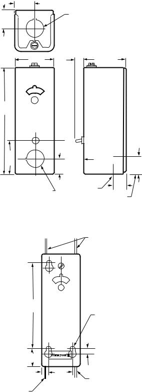
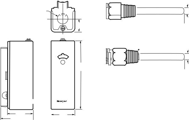
Installation: (See Figures 1, 2, and 3).
Immersion Well: (See Fig. 4).
Boiler Fitting and Bulb: (See Fig. 5).
Accessories and Parts:
137536A Scale Lock Assembly: Includes one 137536-767 Scale Lock and one 80844C-767 Screw, No. 3-48 x 3/16 (5 mm).
Q615A1004 Weatherproof Enclosure (for remote bulb devices only).
107408 Heat-Conductive Compound (4-oz. can). 104488 Spring Clip (stainless steel).
124904 Well Adapter.
Immersion Well Assemblies and Compression Fittings:
See form no. 68-0040, Wells and Fittings for Temperature Controllers, for list and ordering information.
L4006,7,8; L6006,7,8 AQUASTAT® CONTROLLERS
1 (25)
5/16
(8)
KNOCKOUT FOR 3/4 (19 )
CONDUIT ON ALL MODELS. SIMILAR
KNOCKOUT ON BOTTOM FOR
HORIZONTAL INSERTION AND
REMOTE BULB MODELS.
2 (51) |
3/16 |
2-1/8 (54) |
|
(5) |
|
5-5/8
(136)
|
RESET |
|
|
|
BUTTON |
|
|
1-7/8 |
(L4006E, |
|
|
(48) |
L4008E |
3/4 |
|
3/4 |
ONLY) |
||
(19) |
|
(19) |
|
KNOCKOUT FOR 3/4 (19) |
ELEMENT |
|
|
FOR VERTICAL |
11/16 |
||
CONDUIT ON VERTICAL |
|||
INSERTION MODELS ONLY |
IMMERSION |
(18) |
ELEMENT FOR HORIZONTAL IMMERSION
M8957A
Fig. 1. Approximate case installation dimensions in inches (mm) for direct insertion models.
ALTERNATE POSITION
OF SENSING ELEMENT
CAPILLARY
4-3/16
(106)
|
|
MOUNTING |
|
|
|
HOLE FOR |
|
|
|
3/16 IN. (5 MM) |
|
|
|
SCREW (3) |
|
|
13/64 |
|
|
|
(5) |
(3) |
|
15/16 |
|
|
|
(24) |
|
|
|
3/8 (10) |
1-1/4 |
|
|
SENSING |
(32) |
ALTERNATE POSITION |
|
|
|||
|
OF SENSING ELEMENT |
||
ELEMENT |
|
||
|
CAPILLARY |
M8823 |
|
CAPILLARY |
|
||
|
|
||
Fig. 2. Approximate installation dimensions in inches (mm) for remote bulb models. Other dimensions are the same as Fig. 1.
3 |
60-2104—10 |
L4006,7,8; L6006,7,8 AQUASTAT® CONTROLLERS
7/8 IN. (22 MM) STANDARD KNOCKOUT (2)
1
(25)
C
L
5-5/8
(136)
2 (51) |
|
|
|
|
|
|
|
|
|
|
|
|
|
|
|
|
|
|
|
2 (51) |
|
||
|
|
|
|||
2-3/4 (70) 
M8958A
Fig. 3. Approximate installation dimensions in inches (mm) for surface mount models.
 1/2 — 14 IN. NPT
7/16
(11)
 1-1/2 (38)
 3 (76)
  M8789A
Fig. 4. Approximate immersion well dimensions in inches (mm) for all models except L4006C and L6006B.
 1/2 OR 3/4 — 14 IN. NPT
3/8
(10)
 1-5/16 (33)
 3 (76)
  M8799A
Fig. 5. Approximate boiler fitting and bulb dimensions in inches (mm) for L4006C and L6006B.
60-2104—10 |
4 |

L4006,7,8; L6006,7,8 AQUASTAT® CONTROLLERS
Standard Models:
L4006,A,B,C,E,G; L4007,A,B; L4008A,B.E; L6006A,B,C; L6007A, L6008,A,G,H
Table 1. L4006, L4007, L4008 Controller (SPST Switching) Specifications.
|
|
|
Midscale |
|
Switching On |
|
|
|
|
Range |
Differential |
Insertiona |
Temperature |
|
|
Model |
Application |
°F (°C) |
°F (°C) |
Rise |
|
Available Options |
|
L4006A |
High or low |
40° F to 180° F |
2° F or 5° F fixed |
Horizontal |
Breaks |
— |
TRADELINE models |
|
limit |
(4° C to 82° C) |
(1° C or 3° C) |
|
|
|
available. |
|
|
or |
or |
|
|
— |
NPT brass spud 1/2 in. or |
|
|
100° F to 240° F |
5° F to 30° F |
|
|
|
3/4 in. |
|
|
(38° C to 116° C) |
adjustable |
|
|
|
(13 mm to 19 mm) |
|
|
|
(3° C to 17° C) |
|
|
— |
Special capillary assembly. |
|
|
|
|
|
|
— |
Insertion 3-3/8 in. or |
|
|
|
|
|
|
|
5 in. (86 or 127 mm) |
|
|
|
|
|
|
— |
Celsius scale markings. |
|
|
|
|
|
|
— |
Factory-set stops at 160°, |
|
|
|
|
|
|
|
180°, 185°, 200°, 220°, or |
|
|
|
|
|
|
|
230° F (71°, 82°, 85°, 93°, |
|
|
|
|
|
|
|
104°, or 110° C). |
|
|
|
|
|
|
— |
Insulation depths of |
|
|
|
|
|
|
|
1-1/2 in. , 3 in. or 4 in. |
|
|
|
|
|
|
|
(38 mm, 76 mm, or |
|
|
|
|
|
|
|
102 mm). |
|
|
|
|
|
|
— |
Screw and mounting |
|
|
|
|
|
|
|
brackets. |
|
|
|
|
|
|
— Plastic tubing over well. |
|
|
|
|
|
|
|
— Modified dial with stop. |
|
|
|
|
|
|
|
— Special cover and knobs. |
|
|
|
|
|
|
|
— |
With ground screw. |
L4006B |
Circulator |
100° F to 240° F |
5° F (3° C) fixed |
Horizontal |
Makes |
— |
TRADELINE model |
|
|
(38° C to 116° C) |
or 5° F to 30° F |
|
|
|
available. |
|
|
|
(3° C to 17° C) |
|
|
— |
Insulation depth 1-1/2 in. or |
|
|
|
adjustable |
|
|
|
3 in. |
|
|
|
|
|
|
|
(38 mm or 76 mm). |
|
|
|
|
|
|
— NPT brass spud 3/4 in. |
|
|
|
|
|
|
|
|
(19 mm) |
|
|
|
|
|
|
— |
Screw in front of case on |
|
|
|
|
|
|
|
dial suitable for |
|
|
|
|
|
|
|
Powerpile® control. |
|
|
|
|
|
|
— |
Factory-set stop at |
|
|
|
|
|
|
|
240° F (116° C). |
L4006C |
High or low |
65° F to 200° F |
3-1/2° F (2° C) |
Horizontal |
Breaks |
— |
TRADELINE model |
|
limit |
(18° C to 93° C) |
fixed |
direct |
|
|
available. |
|
|
|
|
immersion |
|
— |
Less cover. |
|
|
|
|
|
|
— |
Capillary 10 in. |
|
|
|
|
|
|
|
(254 mm). |
|
|
|
|
|
|
— NPT brass spud 3/4 in. |
|
|
|
|
|
|
|
|
(19 mm). |
L4006Eb |
High limit |
130° F to 290° F |
Manual reset |
Horizontal or |
Breaks |
— |
TRADELINE model |
|
|
(54° C to 141° C) |
|
vertical |
|
|
available. |
|
|
|
|
|
|
— |
Insulation depth |
|
|
|
|
|
|
|
1-1/2 in. or 3 in. |
|
|
|
|
|
|
|
(38 or 76 mm). |
|
|
|
|
|
|
— NPT brass spud 1/2 in. (13 |
|
|
|
|
|
|
|
|
mm) |
|
|
|
|
|
|
— |
Factory-set stop at |
|
|
|
|
|
|
|
250° F (121° C). |
|
|
|
|
|
|
— |
Capillary 8 in. (203 mm). |
aSome models include copper well or fitting; specify when ordering. Also specify boiler tapping size 1/2 or 3/4 in. (13 to 19 mm) NPT and insulation depth.
bManual reset (trip-free) switch breaks circuit and locks out when controlled medium reaches setpoint. Controlled temperature must drop 20° F (11° C) below setpoint before contacts can be manually reset.
5 |
60-2104—10 |

L4006,7,8; L6006,7,8 AQUASTAT® CONTROLLERS
Table 1. L4006, L4007, L4008 Controller (SPST Switching) Specifications. (Cont.)
|
|
|
Midscale |
|
Switching On |
|
|
|
|
Range |
Differential |
Insertiona |
Temperature |
|
|
Model |
Application |
°F (°C) |
°F (°C) |
Rise |
|
Available Options |
|
L4006G |
High limit |
100° F to 200° F |
10° F (6° C) fixed |
Horizontal |
Two switches |
— |
External adjustment knob. |
|
and |
(38° C to 93° C) |
|
|
break |
— |
Insulation depth 4 in. |
|
circulator |
|
|
|
simultaneously |
|
(102 mm). |
|
control |
|
|
|
|
— |
Factory-set stop at |
|
|
|
|
|
|
|
160° F (71° C). |
|
|
|
|
|
|
— |
Celsius scale markings. |
|
|
|
|
|
|
— |
Without well. |
L4007A |
High or low |
100° F to 240° F |
2° F or 5° F |
Horizontal or |
Breaks |
— |
Insulation depth |
|
limit |
(38° C to 116° C) |
(1° C or 3° C) |
vertical |
|
|
1-1/2 in. or 3 in. |
|
|
|
fixed, |
|
|
|
(38 mm or 76 mm). |
|
|
|
5° F to 30° F |
|
|
|
|
|
|
|
(3° C to 17° C) |
|
|
|
|
|
|
|
adjustable |
|
|
|
|
L4007B |
Circulator |
100° F to 240° F |
5° F (3° C) fixed |
Vertical |
Makes |
— |
Celsius scale markings. |
|
|
(38° C to 116° C) |
or |
|
|
|
|
|
|
|
5° F to 30° F |
|
|
|
|
|
|
|
(3° C to 17° C) |
|
|
|
|
|
|
|
adjustable |
|
|
|
|
L4008A |
High or low |
100° F to 240° F |
5° F (3° C) fixed, |
Remote bulb |
Breaks |
— |
Remote capillary |
|
limit |
(38° C to 116° C) |
5° F to 30° F |
direct |
|
|
5-1/2 ft (1.7 m), |
|
|
or |
(3° C to 17° C) |
immersion |
|
|
8-1/2 ft (2.6 m) or |
|
|
130° F to 270° F |
adjustable |
|
|
|
10 ft (3.0 m). |
|
|
(54° C to 132° C) |
|
|
|
— |
Factory-set scale stops at |
|
|
|
|
|
|
|
120°, 170°, or 200° F (49°, |
|
|
|
|
|
|
|
77°, or 93° C) |
|
|
|
|
|
|
— |
Celsius scale markings. |
|
|
|
|
|
|
— |
Front cover screw. |
L4008B |
Circulator |
100° F to 240° F |
5° F (3° C) fixed |
Remote bulb |
Makes |
— |
Capillary 5-1/2 ft |
|
|
(38° C to 116° C) |
or |
direct |
|
|
(1.7 m). |
|
|
|
5° F to 30° F |
immersion |
|
|
|
|
|
|
(3° C to 17° C) |
|
|
|
|
|
|
|
adjustable |
|
|
|
|
L4008Eb |
High limit |
40° F to 80° F |
Manual reset |
Remote bulb |
Breaks |
— |
Factory-set scale stops at |
|
|
(4° C to 27° C) or |
|
|
|
|
140°, 200°, or 250° F (60°, |
|
|
130° F to 270° F |
|
|
|
|
93°, or 121° C). |
|
|
(54° C to 132° C) |
|
|
|
— |
Capillary 5-1/2 ft or |
|
|
|
|
|
|
|
20 ft (1.7m or 6.1 m). |
a Some models include copper well or fitting; specify when ordering. Also specify boiler tapping size 1/2 or 3/4 in. (13 to 19 mm) NPT and insulation depth.
b Manual reset (trip-free) switch breaks circuit and locks out when controlled medium reaches setpoint. Controlled temperature must drop 20° F (11° C) below setpoint before contacts can be manually reset.
60-2104—10 |
6 |
Loading...