


 Loading...
Honeywell
HSVR-04 HSVR-16
Digital Video Recorder
User Manual
© 2010 Honeywell International Inc. All rights reserved. http://www.security.honeywell.com
Rev. A

Honeywell
Contents
1 |
Features and Specifications....................................................................................................... |
1 |
|
Overview............................................................................................................................. |
1 |
|
Features ............................................................................................................................. |
1 |
|
Specification ....................................................................................................................... |
3 |
2 |
Overview and Controls............................................................................................................... |
7 |
|
Front Panel ......................................................................................................................... |
7 |
|
Rear Panel.......................................................................................................................... |
9 |
|
Connection Diagram ......................................................................................................... |
10 |
|
Remote Controller............................................................................................................. |
11 |
|
Mouse Control .................................................................................................................. |
13 |
3 |
Installation and Connections.................................................................................................... |
16 |
|
Check Unpacked DVR...................................................................................................... |
16 |
|
About Front Panel and Rear Panel................................................................................... |
16 |
|
HDD Installation................................................................................................................ |
16 |
|
Connecting Power Supply ................................................................................................ |
18 |
|
Connecting Video Input and Output Devices .................................................................... |
18 |
|
Connecting Video Input .............................................................................................. |
18 |
|
Connecting Video Output ........................................................................................... |
19 |
|
Connecting Audio Input & Output ..................................................................................... |
19 |
|
Audio Input ................................................................................................................. |
19 |
|
Audio Output............................................................................................................... |
19 |
|
Alarm Input and Output Connection.................................................................................. |
20 |
|
Alarm Input and Output Details................................................................................... |
20 |
|
Alarm Input Port.......................................................................................................... |
21 |
|
Alarm Output Port....................................................................................................... |
22 |
|
RS232............................................................................................................................... |
23 |
i

Honeywell
RS485............................................................................................................................... |
23 |
USB .................................................................................................................................. |
24 |
4 Overview of Navigation and Controls....................................................................................... |
25 |
Login, Logout & Main Menu.............................................................................................. |
25 |
Login........................................................................................................................... |
25 |
Main Menu.................................................................................................................. |
26 |
Logout ........................................................................................................................ |
27 |
Auto Resume after Power Failure............................................................................... |
27 |
Replace Button Battery............................................................................................... |
27 |
Manual Record ................................................................................................................. |
28 |
Live Viewing ............................................................................................................... |
28 |
Manual Record ........................................................................................................... |
28 |
Search & Playback ........................................................................................................... |
31 |
Search Menu .............................................................................................................. |
31 |
Basic Operation .......................................................................................................... |
33 |
Calendar..................................................................................................................... |
34 |
Schedule........................................................................................................................... |
35 |
Schedule Menu........................................................................................................... |
35 |
Detect ............................................................................................................................... |
36 |
Go to Detect Menu ..................................................................................................... |
36 |
Motion Detection......................................................................................................... |
37 |
Video Loss.................................................................................................................. |
40 |
Camera Masking ........................................................................................................ |
41 |
Alarm Setup and Alarm Activation .................................................................................... |
42 |
Go to alarm setup interface ........................................................................................ |
42 |
Alarm setup ................................................................................................................ |
42 |
Backup.............................................................................................................................. |
45 |
Detect Device ............................................................................................................. |
45 |
Backup ....................................................................................................................... |
46 |
PTZ Control and Color Setup ........................................................................................... |
48 |
Cable Connection ....................................................................................................... |
48 |
ii

|
Honeywell |
PTZ Setup .................................................................................................................. |
48 |
PTZ Trace................................................................................................................... |
51 |
Preset/Tour/Pattern/Scan Operations............................................................................... |
51 |
Preset Setup............................................................................................................... |
53 |
Activate Preset ........................................................................................................... |
53 |
Patrol setup (Tour Setup) ........................................................................................... |
54 |
Activate Patrol (tour)................................................................................................... |
54 |
Pattern Setup.............................................................................................................. |
54 |
Activate Pattern Function ........................................................................................... |
55 |
Auto Scan Setup......................................................................................................... |
55 |
Activate Auto Scan ..................................................................................................... |
56 |
5 Understanding of Menu Operations and Controls.................................................................... |
57 |
Menu Tree ........................................................................................................................ |
57 |
Main Menu........................................................................................................................ |
59 |
Setting .............................................................................................................................. |
59 |
General....................................................................................................................... |
59 |
Encode ....................................................................................................................... |
61 |
Schedule .................................................................................................................... |
63 |
RS232 ........................................................................................................................ |
63 |
Network ...................................................................................................................... |
64 |
Alarm .......................................................................................................................... |
73 |
Detect ......................................................................................................................... |
73 |
Pan/Tilt/Zoom ............................................................................................................. |
73 |
Display........................................................................................................................ |
74 |
Default ........................................................................................................................ |
77 |
Advanced.......................................................................................................................... |
78 |
HDD Management...................................................................................................... |
79 |
Abnormity ................................................................................................................... |
81 |
Alarm Output .............................................................................................................. |
82 |
Manual Record ........................................................................................................... |
83 |
Account ...................................................................................................................... |
83 |
Auto Maintain.............................................................................................................. |
84 |
TV Adjust.................................................................................................................... |
85 |
iii

Honeywell
|
Information........................................................................................................................ |
86 |
|
HDD Information......................................................................................................... |
86 |
|
BPS ............................................................................................................................ |
87 |
|
Log ............................................................................................................................. |
88 |
|
Version ....................................................................................................................... |
89 |
|
Online Users............................................................................................................... |
90 |
|
Shutdown.......................................................................................................................... |
91 |
6 |
Web Client Operation............................................................................................................... |
93 |
|
Network Connection ......................................................................................................... |
93 |
|
Login................................................................................................................................. |
93 |
|
Real-Time Monitor ...................................................................................................... |
98 |
|
PTZ........................................................................................................................... |
100 |
|
Color......................................................................................................................... |
103 |
|
Picture Path and Record Path .................................................................................. |
104 |
|
Configuration .................................................................................................................. |
105 |
|
System Information................................................................................................... |
105 |
|
System Configuration ............................................................................................... |
109 |
|
Advanced ................................................................................................................. |
129 |
|
Search ............................................................................................................................ |
136 |
|
Alarm .............................................................................................................................. |
140 |
|
About .............................................................................................................................. |
142 |
|
Log out............................................................................................................................ |
142 |
|
Un-install Web Control.................................................................................................... |
143 |
7 |
FAQ ....................................................................................................................................... |
144 |
8 |
Appendix................................................................................................................................ |
151 |
|
HDD Capacity Calculation .............................................................................................. |
151 |
|
Compatible USB Drive List ............................................................................................. |
152 |
iv

Honeywell
Welcome
Thank you for purchasing our DVR!
Please refer to this user’s manual for the installation and operation of HSVR-04 and HSVR-16.
Here you can find information about this series DVR features and functions, as well as a detailed menu tree.
Before installation and operation please read the following safeguards and warnings carefully!
Important Safeguards and Warnings
1. Electrical safety
All installation and operation here should conform to your local electrical safety codes.
We assume no liability or responsibility for all the fires or electrical shock caused by improper handling or installation.
2. Transportation security
Heavy stress, violent vibration or exposure to water is not allowed during transportation, storage and installation.
3. Installation
Keep upwards. Handle with care.
Do not apply power to the DVR before completing installation. Do not place objects on the DVR.
4. Qualified engineers needed
All the examination and repair work should be done by qualified service engineers.
We are not liable for any problems caused by unauthorized modifications or attempted repair.
5. Environment
The DVR should be installed in a cool, dry place away from direct sunlight, inflammable, explosive substances, etc.
6. Accessories
Be sure to use all the accessories recommended by the manufacturer.
Before installation, please open the package and check that all the components are included.
i

Honeywell
Software CD
USB mouse
Network cable
12VDC power adapter
Power cord
SATA data cable and screws for HDD installation
User manual
Remote controller
4 BNC connectors (only in HSVR-04 package)
HDMI cable
Contact your local retailer ASAP if something is broken in your package.
ii

Honeywell
1 Features and Specifications
Overview
HSVR-04 and HSVR-16 are excellent digital video surveillance products. They adopt embedded Linux OS to maintain reliable operation. Popular H.264 compression algorithm and G.711 audio compression technology realize high quality, low bit stream. Unique frame-by-frame play function is suitable for detail analysis. It has various functions such as simultaneous recording, playback, and monitoring as well as guaranteed audio video synchronization. This series product has advanced technology and a strong network data transmission function.
This series device adopts embedded design to achieve high security and reliability. It can work standalone with local Graphic User Interface, and can also be accessed by an IE web client through Ethernet for remote surveillance.
This series product can be widely used in a variety of areas such as intelligent resident zones, banking, telecommunication, electric power, interrogation, transportation, factory, warehouse, resources, and water conservation.
Features
This series product has the following features:
Real-time monitoring
It has an analog (CVBS), VGA and HDMI output port for real-time surveillance by a monitor or TV set.
The system supports the three outputs at the same time.
Storage function
Special data format guarantees data security and avoids vicious data modification.
A/V compression
1

Features and Specifications
Supports multi-channel audio and video. Independent hardware codecs encodes and decodes the audio and video signal from each channel to maintain video and audio synchronization.
Backup function
Provides local backup via USB port for flash disks and portable HDDs IE web client can download the file to local HDD to backup via network.
Recording and playback function
Supports simultaneous real-time recording, record search, forward/backward playback, network monitoring, and record download in all channels.
Supports various playback modes: slow, fast, backward and frame-by- frame playback.
Supports time title overlay for accurate event occurrence time display Supports zoom of specified zone in the picture.
Network operation
Supports remote real-time monitoring, remote record search and remote PTZ control via network.
Alarm interlock function
Three relay alarm outputs to realize alarm interlock and on-site light control.Communication port
RS485 port for PTZ control.
RS232 port for system upgrade and maintenance with PC COM connection, and matrix control.
Standard Ethernet port for network access function.
PTZ control
Supports PTZ decoder via RS-485 communication.
Supports various protocols (KD-6, Scandome, Pelco-D, Pelco-P, etc.) to control the PTZ speed dome.
Intelligent operation
Supports USB Mouse operation function.
In the menu, supports copy and paste for settings.
2
Honeywell
Specification
|
Parameter |
HSVR-04 |
HSVR-16 |
|
|
|
|
|
|
|
Main Processor |
High-performance industrial embedded micro controller |
||
|
|
|
|
|
|
OS |
Embedded LINUX |
|
|
|
|
|
||
|
System |
Multiplex operations: simultaneous multi-channel recording, multi- |
||
System |
Resources |
channel playback and network operation |
||
|
Interface |
User-friendly graphical user interface |
|
|
|
Input Devices |
Front panel, USB mouse, remote control |
||
|
|
|
||
|
Input Method |
Numbers, letters, symbols and extensible Chinese |
||
|
Shortcut |
Copy/paste operation, USB mouse right-key shortcut menu, |
||
|
Function |
double-click USB mouse to switch screen. |
||
Compressio |
Video |
H.264 |
|
|
Compression |
|
|||
n |
|
|
||
|
|
|
||
Audio |
|
|
||
Standard |
G.711A |
|
||
|
Compression |
|
||
|
|
|
||
|
|
4-ch composite video (CVBS) input: |
16-ch composite |
|
Video |
Video Input |
video(CVBS) input: |
||
(NTSC/PAL) BNC (1.0VP- P, 75Ω) |
(NTSC/PAL) BNC (1.0VP- P, |
|||
|
|
|||
|
|
|
75Ω) |
|
|
|
1-ch PAL/NTSC BNC (1.0VP- P, 75Ω) |
composite video (CVBS) |
|
|
|
output; |
|
|
|
Video Output |
1-ch VGA output and 1-ch HDMI output of resolution 800x600, |
||
|
|
1024×768, 1280×720 (720p), 1280×1024 selectable. |
||
|
|
Supports CVBS/VGA/HDMI video output at the same time. |
||
|
Video Standard |
PAL (625 line, 50f/s), NTSC (525 line, 60f/s) |
||
|
Record Speed |
PAL 1f/s to 25f/s per channel and NTSC 1f/s to 30f/s per channel |
||
|
|
|
|
|
|
Video Partition |
1/4 windows |
1/4/8/9/16 windows |
|
|
Monitor Touring |
Supports monitor touring modes: alarm |
triggered, motion detection |
|
|
triggered, and manual control. |
|
||
|
|
|
||
3

Features and Specifications
|
|
|
PAL/NTSC |
|
|
|
PAL/NTSC |
Real-time monitoring: |
|
|
|
D1 704×576/704×480 |
||
|
|
Real-time monitoring: |
||
|
|
Playback: |
||
|
|
D1 704×576/704×480 |
||
|
|
D1 704×576/704×480 (6/7 |
||
|
|
Playback: |
||
|
|
f/s, ch1 & ch9 up to 25/30 |
||
|
|
D1 704×576/704×480 (6/7 f/s, ch1 |
||
|
Resolution |
f/s when other channels are |
||
|
up to 25/30 f/s when other channels |
|||
|
(PAL/NTSC) |
of CIF), CIF 352×288/ |
||
|
are of CIF), CIF 352×288/ 352×240, |
|||
|
|
352×240, QCIF |
||
|
|
QCIF 176×144/176×120 |
||
|
|
176×144/176×120 |
||
|
|
|
||
|
|
Support dual streams: extra stream |
Support dual streams: extra |
|
|
|
resolution QCIF 176×144/176×120 |
||
|
|
stream resolution QCIF |
||
|
|
|
||
|
|
|
176×144/176×120 |
|
|
|
Zone setup: support max 396 (PAL, 22×18) or 330 (NTSC, 22×15) |
||
|
Motion Detection |
zones. |
|
|
|
|
Supports various sensitivity levels. |
|
|
|
Image Quality |
6-level image quality adjustable |
|
|
|
Privacy mask |
Supports max 4 user defined zones of privacy mask in each |
||
|
display window. |
|
||
|
|
|
||
|
OSD in record |
Channels information, time information and privacy mask zone. |
||
|
|
|
||
|
TV Adjust |
Adjusts TV (CVBS) output zone for monitors of display distortion. |
||
|
|
Covers secret channel with blue screen though system is encoding |
||
|
Channel Lock |
normally. |
|
|
|
Screen -lock function to prevent unauthorized user seeing private |
|||
|
|
|||
|
|
video |
|
|
|
Live Channel |
Channel name, recording status, screen lock status, video loss |
||
|
status and motion detection status are shown on the bottom left of |
|||
|
Status OSD |
|||
|
display screen. |
|
||
|
|
|
||
|
Color |
Hue, brightness, contrast, saturation and gain setup for each |
||
|
Configuration |
channel |
|
|
|
Audio Input |
4-ch 200-2000mv10KΩ(BNC) synchronized with video input |
||
Audio |
channel 1-4 |
|
||
|
|
|||
|
Audio Output |
1-ch audio output 200-3000mv 5KΩ(BNC) |
||
Hard disk |
Hard Disk |
1 built-in SATA port; support 1 HDD. |
|
|
Hard Disk Space |
Audio: 28.8MByte/h per channel |
|
||
|
Consumption |
Video: 56-900MByte/h per channel |
|
|
Record and |
|
Manual recording, motion detection recording, schedule recording |
||
Recording Mode |
and alarm recording |
|
||
playback |
Priority: Manual recording> alarm recording>motion detection |
|||
|
||||
|
|
recording>schedule recording |
|
|
|
Recording |
1 to 120 minutes single record duration (Default 60 minutes) |
||
|
Length |
|||
|
|
|
||
|
Cyclic mode |
When hard disk is full, system can overwrite previous video file. |
||
|
Record Search |
Various search engines such as time, type and channel. |
||
|
|
|
||
|
Playback Mode |
Various fast play, slow play speeds, manual frame by frame |
||
|
playback and reverse play mode. |
|
||
|
|
|
||
4
|
|
|
|
Honeywell |
|
|
|
|
|
|
|
|
|
Various File |
Can switch to previous or next file or any file in current play list. |
||
|
|
Can switch to file on other channel of the same time (if existing). |
|
||
|
|
Switch Ways |
Supports continuous file playback; when a file is ended, system |
|
|
|
|
|
automatically plays the next file in the current channel |
|
|
|
|
Multi-channel |
Support maximum 4-channel |
Support maximum 16- |
|
|
|
channel simultaneous |
|
||
|
|
Playback |
simultaneous playback. |
|
|
|
|
playback. |
|
||
|
|
|
|
|
|
|
|
Display Modes |
Switch between adaptive window/full screen during playback |
|
|
|
|
|
|
|
|
|
|
Zoom |
When in one-window full-screen playback mode, you can select |
|
|
|
|
any zone to zoom in. |
|
|
|
|
|
|
|
|
|
|
|
|
HDD backup |
|
|
|
Backup |
Backup Mode |
Support peripheral USB backup device. (Flash disk, portable HDD |
|
|
|
and etc.) |
|
|
||
|
function |
|
|
||
|
|
Supports USB burner (extension function). |
|
||
|
|
|
|
||
|
|
|
Supports network download and backup |
|
|
|
|
|
Remote live view of all channels. |
|
|
|
|
|
DVR configuration through web browser client |
|
|
|
|
|
Upgrade or maintenance via web browser client |
|
|
|
Network |
|
View alarm information such as external alarm, motion detection |
|
|
|
Network control |
and video loss |
|
|
|
|
Function |
|
|
||
|
|
Supports network PTZ control |
|
|
|
|
|
|
|
|
|
|
|
|
File download backup and playback |
|
|
|
|
|
Duplex transparent COM |
|
|
|
|
|
Intercom |
|
|
|
|
|
Zone setup: 396 (PAL, 22×18) or 330 (NTSC, 22×15) detection |
|
|
|
|
|
zones. |
|
|
|
|
Motion Detection |
Various sensitivity levels |
|
|
|
|
|
Can activate recording, external alarm or screen message prompt |
|
|
|
|
|
in specified period. |
|
|
|
Motion |
Video Loss |
Alarm can activate external alarm or screen message prompt. |
|
|
|
External Alarm |
Can activate recording, external alarm or screen message prompt |
|
||
|
Detection |
|
|||
|
in specified period. |
|
|
||
|
and Alarm |
|
|
|
|
|
Manual Alarm |
Enables or disables alarm input channel. |
|
||
|
|
|
|||
|
|
Control |
Supports manual alarm output. |
|
|
|
|
Alarm Input |
4-ch alarm input Normal open or |
16-ch alarm input Normal |
|
|
|
normal close |
open or normal close |
|
|
|
|
|
|
||
|
|
Alarm Output |
3-channel relay output |
|
|
|
|
Alarm Relay |
30VDC 2A 125VAC 1A activation alarm |
|
|
|
|
USB Interface |
2 USB 2.0 ports |
|
|
|
|
Network |
RJ45 10M/100M self-adaptive Ethernet port |
|
|
|
|
connection |
|
||
|
|
|
|
|
|
|
Interface |
|
PTZ control port |
|
|
|
RS485 |
Supports various control protocols: KD-6, Scandome, Pelco-D, |
|
||
|
|
|
|||
|
|
|
Pelco-P, etc. |
|
|
|
|
RS232 |
Ordinary serial port (for upgrade and maintenance) and transparent |
|
|
|
|
serial port (COM input and output via network ) |
|
||
|
|
|
|
||
|
System |
Hard Disk |
Displays HDD current status |
|
|
|
Information |
Information |
|
|
|
|
|
|
|
||
5

Features and Specifications
|
Data Stream |
Data stream statistics for each channel (in wave mode) |
|
|
Statistics |
||
|
|
||
|
Log statistics |
Display maximum1024 logs. |
|
|
Support various search engines such as time and type. |
||
|
|
||
|
Version |
Display version information: channel amount, alarm input and |
|
|
output amount, system version and published date. |
||
|
|
||
|
On-line user |
Display current on-line user |
|
|
|
Multi-level user management; various management modes |
|
|
User |
Integrated management for local user and network user |
|
|
Configurable user power |
||
|
Management |
||
User |
Support user /group and its corresponding rights modification. |
||
|
|||
Managemen |
|
No limit to the user or group amount |
|
t |
|
Password modification |
|
|
Password |
Administrator can modify other user’s password. |
|
|
Authentication |
Account lock strategy |
|
|
|
Five times login failure in thirty minutes may result in account lock. |
|
Upgrade |
|
Web browser, client-end and specific update tool. |
|
|
|
Password login protection to guarantee safety |
|
|
|
|
|
Login, Logout and Shutdown |
User-friendly interface when login. Provide the following options: |
||
logout /shutdown/ restart. |
|||
|
|
Authentication when shut down to make sure only authorized users |
|
|
|
can turn off DVR |
|
|
Power |
DC +12V/3.3A |
|
|
|
|
|
|
Power |
12W (Exclude HDD) |
|
|
Consumption |
||
|
|
||
|
Working |
0 55 |
|
|
Temperature |
||
General |
|
||
Working |
10% 90% |
||
Parameter |
Humidity |
||
|
|||
|
Air Pressure |
86kpa 106kpa |
|
|
Dimension |
375x285x45mm |
|
|
|
|
|
|
Weight |
3.25KG(Exclude HDD) |
|
|
Installation Mode |
Desktop installation |
|
|
|
|
|
6
Honeywell
2 Overview and Controls
This section provides information about front panel and rear panel. When you install this series DVR for the first time, please refer to this part first.
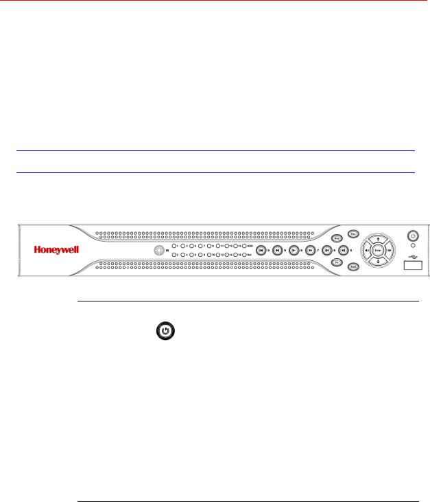
Front Panel
The front panel is shown in Figure 2-1.
Figure 2-1 The Front Panel of HSVR-04/HSVR-16
Please refer to the following sheet for front panel button information.
Name |
Icon |
Function |
||
|
|
|
|
|
Power button |
|
|
Power button, press this button for three seconds to boot |
|
|
|
up or shut down DVR. |
||
|
|
|
||
|
|
|
|
|
Shift |
Shift |
In textbox, click this button to switch between numeral, |
||
English (Small/Capitalized), donation and etc. |
||||
|
|
|
||
|
|
|
|
|
|
|
|
Activate current control, modify setup, and then move up |
|
|
|
|
and down. |
|
Up/1 |
|
|
|
|
|
Increase/decrease numeral. |
|||
Down/4 |
|
|||
|
|
Assistant function such as PTZ menu. |
||
|
|
|
||
|
|
|
|
|
|
|
|
In text mode, input number 1/4. |
|
|
|
|
|
|
|
|
|
Shift current activated control, |
|
|
|
|
|
|
Left/2 |
|
|
During playback, click these buttons to control playback |
|
Right/3 |
bar. |
|||
|
|
|||
In text mode, input number 2/3.
7

Overview and Controls
|
ESC |
ESC |
Go to previous menu, or cancel current operation. |
|
|
||
|
During playback, click it to restore real-time monitor mode. |
||
|
|
|
|
|
|
|
|
|
|
|
Confirm current operation |
|
Enter |
ENTER |
|
|
Go to default button |
||
|
|
|
|
|
|
|
Go to menu |
|
|
|
|
|
Record |
REC |
Manually stop/start recording, working with direction keys |
|
or numeral keys to select the recording channel. |
||
|
|
|
|
|
|
|
|
|
Slow play/8 |
|
Multiple slow play speeds or normal playback. |
|
|
In text mode, input number 8. |
|
|
|
|
|
|
|
|
|
|
|
|
One-window monitor mode, click this button to display |
|
|
|
assistant function: PTZ control and image color. |
|
|
|
In PTZ menu, shift PTZ control menu. |
|
|
|
|
|
|
|
Backspace function: in numeral control or text control, it |
|
|
|
can delete the previous character before the cursor. |
|
|
|
|
|
|
|
In motion detection setup, work with Fn and direction keys |
|
Assistant |
Fn |
to realize setup. |
|
|
|
In preview mode, click it for three seconds to switch |
|
|
|
between TV.VGA. For HD1 series DVR, there are three |
|
|
|
modes: TV, VGA, VGA_LCD (60Hz LED output). |
|
|
|
In text mode, click it to switch between numeral, English |
|
|
|
character(small/capitalized) and etc. |
|
|
|
|
|
|
|
Realize other special functions. |
|
|
|
|
|
Fast play/7 |
|
Various fast speeds and normal playback. |
|
In text mode, input number 7. |
||
|
|
|
|
|
|
|
|
|
Play previous/0 |
│ |
In playback mode, playback the previous video |
|
In text mode, input number 0. |
||
|
|
|
|
|
|
|
|
|
|
|
In normal playback or pause mode, click this button to |
|
Reverse/Pause/6 |
|
reverse playback |
|
In reverse playback, click this button to pause playback. |
||
|
|
|
|
|
|
|
In text mode, input number 6. |
|
|
|
|
|
|
|
In playback mode, playback the next video |
|
Play Next/9 |
│ |
In menu setup, go to the bottom of the dropdown list. |
|
|
|
In text mode, input number 9. |
|
|
|
|
|
|
|
In normal playback click this button to pause playback |
|
Play/Pause /5 |
|
In reverse playback or pause mode, click this button to |
|
resume normal playback. |
||
|
|
|
|
|
|
|
In live view, press this key to enter Search interface. |
|
|
|
|
8
|
|
|
Honeywell |
||
|
|
|
|
|
|
|
|
|
In text mode, input number 5. |
||
|
|
|
|
|
|
|
USB port |
|
To connect USB storage device, USB mouse. |
||
|
|
|
|
|
|
|
Network |
Net |
Network error occurs or there is no network connection, the |
||
|
abnormal |
||||
|
light becomes red to alert you. |
||||
|
indicator |
|
|||
|
|
|
|
|
|
|
HDD abnormal |
HDD |
HDD error occurs or HDD capacity is below specified |
||
|
indicator |
threshold value, the light becomes red to alert you. |
|||
|
|
||||
|
|
|
|
|
|
|
Record indicator |
Alarm |
Indicates whether the system is recording or not. It turns on |
||
|
when the system is recording. |
|
|||
|
|
|
|||
|
IR Receiver |
IR |
Receives the signal from the remote control. |
||
|
|
|
|
|
|
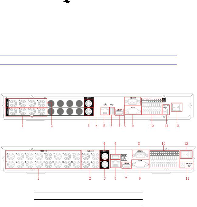
Rear Panel
HSVR-04 and HSVR-16 rear panels are shown as below. See Figure 2-2 and Figure 2-3.
Figure 2-2 The Rear Panel of HSVR-04
Figure 2-3 The Rear Panel of HSVR-16
Please refer to the following table for detailed information.
No. Description
1 Video input
9

Overview and Controls
2Audio input
3Video CVBS output
4Audio output
5Network port
6USB port
7HDMI port
8RS232 port
9Video VGA output
10Alarm input/alarm output/RS485 port
1112VDC Power input port
12Power button
When connecting the Ethernet port, please use a straight cable to connect the PC and use the crossover cable to connect to the switcher or router.
Connection Diagram
Please refer to Figure 2-4 for connection diagram of HSVR-16. HSVR-04’s is similar.
10

Honeywell
Figure 2-4 Device Connection
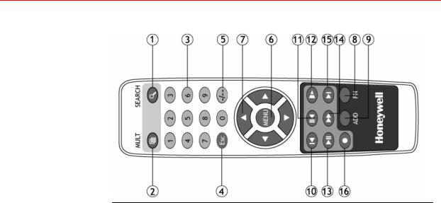
Remote Controller
The remote controller interface is shown as in Figure 2-5.
11
Overview and Controls
Figure 2-5 Remote Controller
No. |
Function |
|
|
1 |
Record search |
|
|
2 |
Multiple-window switch |
|
|
3 |
0-9 number keys |
|
|
4 |
ESC, Cancel |
|
|
5 |
Reserved, not effective for HSVR-04 and HSVR-16 |
|
|
6 |
Confirm /menu key |
|
|
7 |
Direction keys |
|
|
8 |
Auxiliary function key |
|
|
9 |
Remote address switch |
|
|
10 |
Previous |
|
|
11 |
Backward playback |
|
|
12 |
Slow play |
|
|
13 |
Play/Pause |
|
|
14 |
Fast play |
|
|
15 |
Next |
|
|
16 |
Record |
|
|
12
Honeywell
Mouse Control
Left click mouse
The password input dialogue box will pop up if you have not logged in.
In real-time monitor mode, you can go to the main menu.
When you have selected one menu item, left click the mouse to view menu content.
Implement the control operation.
Modify checkbox or motion detection status.
Click combo box to bring up the drop down list
13

Overview and Controls
In input box, you can select input methods. Left click the corresponding button on the panel where you can input numeral/English character (small/capitalized). Here ← stands for the backspace button. stands for the space button.
In English input mode: _stands for input a backspace icon and ← stands for deleting the previous character.
In numeral input mode: _ stands for clear and ← stands for deleting the previous numeral.
When inputting special symbols, you can click the corresponding numeral in the front panel to input. For example, click numeral 1 you can input“/” , or you can click the numeral in the on-screen keyboard directly.
Double left click mouse
Implement special control operation such as double click one item in the file list to playback the video.
In multiple-window mode, double left click one channel to view in full-window.
Double left click current video again to go back to previous multiple-window mode.
14

Honeywell
|
In real-time monitor mode, the shortcut menu will appear: one- |
|
|
window, four-windows, eight-window, nine-windows and |
|
|
sixteen-windows, Pan/Tilt/Zoom, color setting, search, record, |
|
|
alarm input, alarm output, and main menu. |
|
Right click |
Among which, Pan/Tilt/Zoom and color setting applies for the |
|
current selected channel. If you are in multiple-window mode, |
||
mouse |
||
the system automatically switches to the corresponding |
||
|
||
|
channel. |
|
|
|
|
|
Exit current menu without saving the modification. |
|
|
|
|
|
In numeral input box: Increase or decrease numerical value. |
|
Press middle |
|
|
Switch the items in the check box. |
||
button |
||
|
||
|
Page up or page down |
|
|
|
|
Move mouse Selects current control or move control |
||
|
|
|
Drag mouse |
Selects motion detection zone |
|
|
||
Selects privacy mask zone. |
||
|
||
|
|
|
15

Installation and Connections
3 Installation and Connections
Note |
All the installation and operations here should conform to |
|
your local electrical safety rules |
||
|
||
|
|
Check Unpacked DVR
When you receive the DVR from the forwarding agent, please check whether there is any visible damage. The protective materials used for the package of the DVR can protect during most transportation caused accidentsal. Then proceed to open the box to check the accessories.
Please check the items in accordance with the list on the warranty card. Finally you can remove the protective film of the DVR.
About Front Panel and Rear Panel
For detailed information of the function keys in the front panel and the ports in the rear panel, please refer to the User’s Manual included in the resource CD.
The model in the front panel is very important; please check according to your purchase order.
The label in the rear panel is very important too. Usually we need you to present the serial number when we provide service after sales.
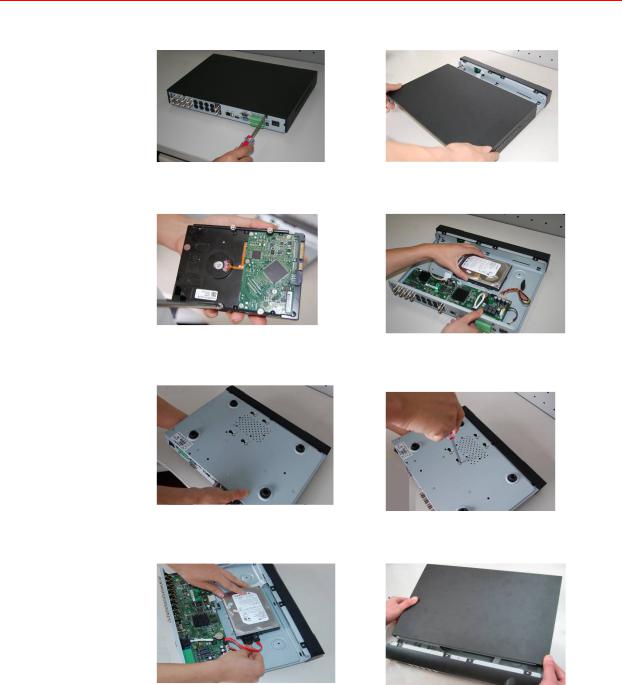
HDD Installation
This series DVR has only one SATA HDD. Please use HDD of 7200rpm or higher.
You can refer to the user guide for a recommended HDD brand.
16
Honeywell
Please follow the instructions below to install the hard disk.
1. Loosen the screws of the upper |
2. Remove upper cover |
cover. |
|
3. Rotate four screws three times to secure HDD bracket..
4. Place the HDD in accordance with the four holes in the chassis.
5. Turn the device upside down and then turn the screw in firmly.
6. Fix the HDD firmly.
7. Connect the HDD cable and power cable.
8. Connect the HDD cable and power cable.
17

Installation and Connections
After completing HDD installation, please check the connection of the data ribbon and power cord.
Connecting Power Supply
Please check whether the input voltage and device power button match.
We recommend you use UPS to guarantee steady operation, DVR life span, and other peripheral equipments’ operation such as cameras.
Connecting Video Input and Output Devices
Connecting Video Input
The video input interface is BNC. The input video format includes: PAL/NTSC BNC(1.0VP- P 75Ω).
The video signal should comply with your national standards.
The input video signal should have high SNR, low distortion, low interference, natural color and suitable lightness.
Guarantee the stability and reliability of the camera signal:
The camera should be installed in a cool, dry place away from direct sunlight, inflammable, explosive substances, etc.
The camera and the DVR should have the same grounding to ensure normal operation of the camera.
Guarantee the stability and reliability of the transmission line
Please use high quality, sound shielded BNC. Please select suitable BNC model according to the transmission distance.
If the distance is too long, you should use twisted pair cable, and you can add video compensation devices or use optical fiber to ensure video quality.
You should keep the video signal away from the strong electromagnetic interference, especially the high tension current.
Keep connection lugs in well contact
The signal line and shielded wire should be fixed firmly and in well connection. Avoid dry joint, lap welding and oxidation.
18

Honeywell
Connecting Video Output
Video output includes BNC (CVBS PAL/NTSC, 1.0VP-P, 75Ω), VGA and HDMI.
The system supports the three kinds of outputs at the same time.
When you are using PC monitor to replace standard CCTV monitor, please pay attention to the following points:
To extend the product’s life, do not run the pc monitor for a long time.
Regular demagnetization will keep device maintaining proper status.
Keep it away from strong electromagnetic interference devices.
Using TV as video output device is not a reliable substitution method. You also need to reduce the working hour and control the interference from power supply and other devices. The low quality TV may result in device damage.
Connecting Audio Input & Output
Audio Input
The four audio input channels are bound to video input channel 1-4. Use the BNC connector to connect the audio channel.
Due to high impedance of audio input, please use active sound pick-up.
Audio transmission is similar to video transmission. Try to avoid interference, dry joint, and it shall be away from high tension current
Audio Output
The audio output signal parameter is usually over 200mv 1KΩ (BNC). It can directly connect to low impedance earphones, active sound box or amplifier-drive audio output device.
If the sound box and the pick-up cannot be separated spatially, it is easy to cause a squeaking noise. In this case you can adopt the following measures:
Use better sound pick-up with better directing property.
19

Installation and Connections
Reduce the volume of the sound box.
Use more sound-absorbing materials in decoration to reduce voice echo and improve acoustics environment.
Adjust the layout to reduce the occurrence of the squeaking.
Alarm Input and Output Connection
Please refer to the following sheet for alarm input and output connection.
There are two alarm input types for you to select: normal open (NO) and normal close (NC).
1. Alarm input
aPlease make sure alarm input mode is grounding alarm input.
bGrounding signal is needed for alarm input.
cWhen you are connecting two DVRs or connecting one DVR and one other device, please use a relay to separate them
2.Alarm output
The alarm output port should not be connected to a high power load directly (It shall be less than 1A) to avoid high current which may result in relay damage. Please use the co contactor to realize the connection between the alarm output port and the load.
3.Please make sure the front-end devices have been well earthed. Improper grounding may result in chip damage.
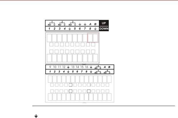
Alarm Input and Output Details
You can refer to the following sheet and Figure 3-1 for alarm input and output information.
20
Honeywell
Figure 3-1 Alarm Input and Output of HSVR-04 (Left) and HSVR-16 (Right)
Parameter |
Grounding Alarm |
|
|
|
Ground line |
|
|
|
HSVR-04: 1, 2, 3, 4 become valid in low voltage; 5, 6, 7, 8 are not |
Alarm Input |
effective. |
|
HSVR-16: 1-16 become valid in low voltage. |
|
|
Relay Output NO C |
1-NO C, 2-NO C, 3-NO C Three Normal Open activation outputs. |
|
|
|
RS-485 communication port. They are used to control devices |
RS-485 A/B |
such as PTZ. Please parallel connect 120Ω between A/B cables if |
|
there are too many PTZ decoders. |
|
|
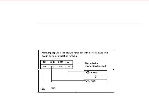
Alarm Input Port
4-ch (HSVR-04) / 16-ch (HSVR-16)grounding alarm inputs. (Normal open or Normal close type)
Please parallel connect COM end and GND end of the alarm detector (Provide external power to the alarm detector).
Please parallel connect the ground of the DVR and the ground of the alarm detector.
21
Installation and Connections
Please connect the NC port of the alarm sensor to the DVR alarm input (ALARM)
Use the same ground with that of DVR if you use external power for the alarm device.
Note |
Only indoor devices are recommended for being connected |
|
to HSVR-04 / HSVR-16 alarm inputs. |
||
|
||
|
|
Figure 3-2 Sample of Alarm Input (Normal Close Type)
Alarm Output Port
Three ways to relay alarm output (NO contact). External power supply is needed for external alarm device.
To avoid overloading, please read the following relay parameters sheet carefully.
Relay Specification:
Model |
JRC-27F |
|
|
|
|
Material of the touch |
Silver |
|
|
|
|
|
Rated switch capacity |
30VDC 2A, 125VAC 1A |
|
|
|
Rating (Resistance |
Maximum switch power |
125VA 160W |
Load) |
Maximum switch voltage |
250VAC, 220VDC |
|
||
|
|
|
|
Maximum switch currency |
1A |
|
|
|
22
Loading...