


 Loading...
HE105, HE205
Whole Home Bypass Humidifier
INSTALLATION INSTRUCTIONS
APPLICATION
This kit contains your new HE105 or HE205 Humidifier, H8908 Humidistat and all the accessories required for installation.
PREPARING FOR THE
INSTALLATION
Be sure to identify all the required (Table 1) accessories (included) and make sure the appropriate tools are available before beginning the installation.
Included in the box:
•Humidifier
•H8908 Humidistat
•Plug-in transformer
Canadian “C” models also include:
•6 in. dia. bypass ducting (24 in.)
•18 gauge thermostat wire (20 ft.)
•1/4 in. (6.35 mm) OD feed water tubing (20 ft.)
•1/2 in. (12.7 mm) ID drain tubing (10 ft.)
•Saddle valve
How Your Humidifier Works
Your humidifier uses the principle that vapor (evaporated water) is created when warm air blows over a water-soaked area. As the vapor circulates, the relative humidity rises.
Your humidity control monitors the relative humidity and activates the humidifier accordingly. The humidifier has a water supply that dispenses water evenly over a humidifier pad. The warm dry air from the furnace passes over the humidifier pad and picks up the moist air to circulate it throughout your home.
Humidified air feels warmer and more comfortable so you may be able to lower your thermostat heating setpoint, which saves money on your heating fuel bills. The end result is that your humidifier gives you a comfortable environment that is also energy efficient.
Need Help?
For assistance with this product please visit http://honeywellhome.com or call Customer Care toll-free at 1-800-468-1502.
Required Tools
Tools required for installation include:
•Tin snip
•Screwdriver
•Pliers
•Adjustable or open-end wrench
•Drill
•Level
•3/4 in. (19 mm) sheet metal drill bit
SPECIFICATIONS
Model specific specifications are shown in Table 1.
Operating Ambient Temperature: 41 to 113 °F (5 to 45 °C) Power Supply: 24 VAC / 60 Hz.
Power Consumption: 7 Watts with 24 Vrms Water Pressure: 40 to 120 psi.
Orifice Output: .02 in. (0.5 mm)
Flow Rate at Nozzle: 4.7 GPH (18 L/hr.) under 120 psi
Table 1. Specifications.
|
|
|
|
|
|
|
Size |
Duct Opening |
|
Evaporation |
|
Model |
length × width × depth |
H × W |
Pad Size |
Output |
|
|
|
|
|
|
|
HE105 |
15.16 × 16.57 × 9.47 in. |
9.43 × 9.28 in. |
10 × 9.5 × 1.5 in. |
12 GPD |
|
(385 × 421 × 240 mm) |
(240 × 236 mm) |
(254 × 241 × 38.1 mm) |
|||
|
|
||||
|
|
|
|
|
|
HE205 |
18.30 × 17.11 × 9.59 in. |
12.63 × 9.68 in. |
13.125 × 10 × 1.5 in. |
17 GPD |
|
(465 × 434 × 243 mm) |
(321 × 246 mm) |
(333 × 254 × 38.1 mm) |
|||
|
|
||||
|
|
|
|
|
33-00229EF-03
HE105, HE205 WHOLE HOME BYPASS HUMIDIFIER
Safety Definitions
These safety terms identify information you must read prior to installing or operating the humidifier.
 WARNING
Indicates a hazardous situation which, if not avoided, could result in death or serious injury.
 CAUTION
Indicates a hazardous situation which, if not avoided, could cause bodily injury or property damage.
Safety Precautions
Make sure you read and understand the following safety hazards before installing, using, or working with the humidifier:
 WARNING
Serious Personal Injury Hazard.
Can cause electrical shock and injury from moving parts.
Disconnect power and shut off water supply before removing cover.
 WARNING
Hazardous Voltage
Can cause personal injury or equipment damage.
Do not cut or drill into any air conditioning or electrical accessory.
 CAUTION
Chemical Hazard.
Can cause personal injury or equipment damage.
Do not use any line connected to an air conditioner. Do not use gas line.
 CAUTION
Temperature and Static Pressure Hazard. Can cause property or equipment damage.
Locate humidifier where ambient temperature is between 41 and 113 °F (5 to 45 °C).
Do not install humidifier where freezing temperatures could occur.
Be sure supply plenum static pressure is no greater than 0.4 in. wc and water pressure is no greater than 120 psi.
 CAUTION
Sharp Edges Installation Hazard.
Can cause personal injury.
Wear gloves and safety glasses.
IMPORTANT
Read and save these instructions.
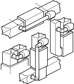
Determining Best Location for Humidifier
•Select a location for the humidifier on the supply (warm air stream) duct. See Fig. 1 for examples. Return duct mounting is acceptable if there are space restrictions on the supply duct. If you are mounting the humidifier on the return duct, simply swap “return duct” for “supply duct” throughout these instructions.
•Select a location that cannot damage the air conditioner A-coil during installation.
•Do not locate the humidifier on the furnace body.
•Mount the humidifier in a conditioned space to prevent freezing.
•Mount the humidifier at least 3 in. (78 mm) above the furnace body to allow adequate space for the solenoid valve and drain line.
HUMIDIFIER
BYPASS
COLLAR
HIGHBOY
LOWBOY
M12248D
Fig. 1. Typical humidifier installation locations.
33-00229EF—03 |
2 |

HE105, HE205 WHOLE HOME BYPASS HUMIDIFIER
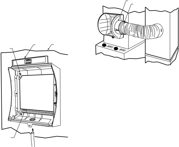
CHOOSE A LOCATION IN A CONDITIONED
SPACE THAT HAS ACCESS TO A WATER SUPPLY
PIPE. COLD OR HOT WATER CAN BE USED.
SELECT A SURFACE ON THE HVAC SUPPLY OR
RETURN DUCT WITH CLEARANCE FOR THE
SOLENOID VALVE, DRAIN LINE AND COVER
REMOVAL.
 LOCATION MUST ALSO HAVE ACCESS TO 120
VAC POWER.
ENSURE THE LOCATION IS NEAR A DRAIN.
CONSULT LOCAL PLUMBING CODES FOR
PROPER DRAINAGE.
M33410
Fig. 2. Typical humidifier installation locations.
Selecting Location for Humidistat
•Select a location for the humidistat on the return plenum or on the wall in the living space.
•Mounting on the return plenum is the easiest installation for the control wiring circuit.
•Make sure that the thermostat wire is adequate to reach from the humidifier to the humidistat, and also from the humidifier to the transformer. See “Wiring” on page 5 for more information.
IMPORTANT
The humidistat must be mounted upstream from the humidifier or bypass duct to ensure it is properly sensing the relative humidity of the living space. Locate the control at least 8 in. (203 mm) upstream from the humidifier in the return air duct. (See Fig. 3.)
|
ALTERNATE LOCATION |
RETURN |
RETURN |
AIR |
AIR |
6 in. (152 mm)
MINIMUM
 15 in. (381 mm) MINIMUM
BEST
LOCATION
RETURN AIR DUCT 
M12831
Fig. 3. Selecting duct location for humidistat.
INSTALLATION
1.Turn off power to the air handling system at the circuit breaker.
2.Draw a level line on the plenum in the selected location.
IMPORTANT
Be sure the mounting template is level before marking. Use of a small level is recommended.
3.Locate the template (form number 33-00210, included in the box). For the HE105 model, cut out the template along the dotted line. For the HE205 model, use the entire sheet as a template.
4.Tape the template in position and trace around the template.
5.Remove the template and carefully cut the rectangular opening using tin snips.
6.Disassemble the humidifier; remove the cover and take out the humidifier pad assembly. See Fig. 4.
WATER
FEED NOZZLE
HUMIDIFIER

PAD ASSEMBLY
FRAME
COVER
SIDEWALL
 HUMIDIFIER
HOUSING
BY-PASS SIDEWALL |
WATER |
|
FEED TUBE |
M31022B |
Fig. 4. Disassembling humidifier.
3 |
33-00229EF—03 |
HE105, HE205 WHOLE HOME BYPASS HUMIDIFIER
7.Make sure the humidifier housing is level, then position it in the opening so the plastic tabs are in place on the lower sheet metal edge of the opening. Use pliers, as necessary, to flatten cut edges. See Fig. 5.
8.Secure the humidifier housing to the opening at the top and bottom using sheet metal screws.
9.Reassemble humidifier side plates to customize the orientation for your specific install. The side plate with the humidifier port needs to be on the side of the humidifier that is closest to the bypass ducting. Be sure to open the bypass flap for use and close it when the humidifier is not used. See Fig. 6.
SHEET METAL |
LEVEL |
DUCT |
|
|
|
SCREWS (4) |
|
|
HUMIDIFIER PORT
CONNECTOR STRAP
OPENING
TO AIR DUCT
PLASTIC
TABS (2)
DRAIN TUBING 
M36295
Fig. 5. Installing humidifier on duct.
10.Slide bypass duct over the humidifier port on the HE105/HE205, making sure that the flex duct advances past the raised plastic tabs on the port. These tabs will help to hold the flex duct in place. Verify that the damper blade has adequate clearance to move back and forth between the closed and open positions. Secure the flex duct in place with the plastic connector strap.
11.Seal the duct connections with foil tape. Seal both
1)the connection between the starter collar end of the flex duct and the home's duct work and
2)the end of the flex duct to the humidifier over the top of the connector strap.
12.Reinstall the humidifier pad assembly in the humidifier housing.
13.Hinge the cover in place and secure with the thumbscrew located at the bottom of the cover.
M36298
Fig. 6. Connecting bypass ducting.
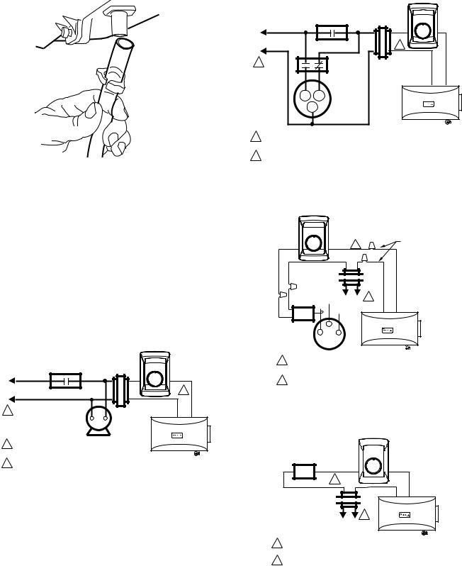
Connecting the Plumbing
1.Hot or cold water, either hard or softened, can be used in the humidifier. Cut the water line so it reaches from the humidifier to the main water supply tap.
2.Turn off water supply and tap into a water line.
•Consult local codes for proper plumbing.
•Use an approved saddle valve or a T-fitting and manual shutoff valve to tap into the water line.
•Refer to the literature included with the valve you chose and the local plumbing codes. Use proper technique for the valve.
•Connect the other end of the humidifier water line to the water valve.
•Use 1/4 in. O.D. copper tubing and connect to inlet side of solenoid valve via a compression fitting or Quick Connect fitting.
•Place brass compression nut over copper tubing.
NOTE: Do not over tighten compression nut.
•Moderate tightness prevents leaking.
•Slide the brass ferrule over the tubing.
•Insert tubing into solenoid valve fitting and support the valve while tightening the compression nut.
3.Connect a water drain line.
•Consult and follow local plumbing codes for drain pipe size and flow requirement.
•The ideal installation is directly to the main floor drain using a rubber drain hose.
a.Slide a drain clamp over the tubing.
b.Push the tubing over the drain nipple on the humidifier.
c.Route the drain hose to the floor drain. The hose must have a continuous downward slope.
d.Direct the hose outlet into the floor drain. Secure the hose to reduce the risk of water pooling or splashing as it drains from the humidifier. See Fig. 7.
33-00229EF—03 |
4 |
HE105, HE205 WHOLE HOME BYPASS HUMIDIFIER
H8908
M20177
Fig. 7. Installing the drain tubing.
WIRING
 CAUTION
Hazardous Voltage.
Can cause personal injury or equipment damage.
Disconnect power supply before installing or servicing equipment.
IMPORTANT
All wiring must comply with applicable local code, ordinances and regulations.
Wire the humidifier, humidistat and transformer. See Fig. 8—11.
H8908
|
|
30 |
40 |
|
|
|
20 |
50 |
|
L1 |
|
10 |
60 |
|
(HOT) |
POWER |
OFF |
ON |
|
FAN CONTROL |
2 |
|||
|
SUPPLY |
|||
L2 |
|
|
|
|
1 |
|
TRANSFORMER |
||
FURNACE
FAN
MOTOR
1 PROVIDE DISCONNECT MEANS AND OVERLOAD PROTECTION AS REQUIRED.
HUMIDIFIER
2 24 VAC WIRING.
M24727
Fig. 8. Wiring diagram with H8908 (included).Transformer
powered when single speed fan is energized.*
L1 |
|
|
|
|
(HOT) |
POWER |
FAN CONTROL |
||
|
SUPPLY |
|||
L2 |
|
|
|
|
1 |
|
|
|
DPST |
|
|
|
SWITCHING |
|
|
|
|
|
|
|
|
|
|
RELAY |
|
H |
|
L |
2-SPEED |
|
|
FAN |
||
|
|
|
|
|
|
|
C |
|
MOTOR |
|
|
|
|
|
30 |
40 |
20 |
50 |
10 |
60 |
OFF |
ON |
2 |
|
TRANSFORMER
HUMIDIFIER
1POWER SUPPLY. PROVIDE DISCONNECT MEANS AND OVERLOAD PROTECTION AS REQUIRED.
M24728
2 24 VAC WIRING.
Fig. 9. Wiring diagram with H8908 (included). Transformer powered when two speed fan is energized.*
H8908
30 |
40 |
|
WATER |
20 |
50 |
|
|
10 |
60 |
2 |
SOLENOID |
OFF |
ON |
|
LEAD WIRE |
TRANSFORMER 

L2 L1 1 (HOT)
CURRENT
SENSING LO
RELAY C HI
HUMIDIFIER 
1POWER SUPPLY. PROVIDE DISCONNECT MEANS AND OVERLOAD PROTECTION AS REQUIRED.
2 24V WIRING. |
M24729 |
Fig. 10. Wiring diagram with H8908 (included) and current sensing relay (not included).*
H8908
AIR |
|
|
PRESSURE SWITCH/ |
|
40 |
SAIL SWITCH |
30 |
|
20 |
50 |
|
|
10 |
60 |
|
OFF |
ON |
|
2 |
|
TRANSFORMER 

1
L2 L1
(HOT) HUMIDIFIER
1POWER SUPPLY. PROVIDE DISCONNECT MEANS AND OVERLOAD PROTECTION AS REQUIRED.
2 24V WIRING. |
M24730C |
Fig. 11. Wiring diagram with H8908 (included) and sail switch (not included).*
*When a thermostat with IAQ control is used instead of a humidistat, it simplifies the wiring circuit. The thermostat U contacts are installed in place of the H8908 and the sail switch or other relay is removed from the circuit.
5 |
33-00229EF—03 |
HE105, HE205 WHOLE HOME BYPASS HUMIDIFIER
TESTING HUMIDIFIER
OPERATION
Checklist
Humidifier is level.
Control wiring was reviewed using circuit diagram.
Humidifier has power.
Water feed line has no kinks.
Drain line slopes continuously down and ends at floor drain.
Water hose inside humidifier is connected to PerfectFLO™ water distribution tray.
After installation use the following steps to check the humidifier operation:
1.Turn on the power and the water supply.
2.Ensure the saddle valve or T-valve fitting is fully opened by turning the handle to the left (counter clockwise) until there is resistance.
3.Turn the H8908 Humidistat to On and turn on the heat by setting the thermostat to 10 ºF (6 ºC) above room temperature.
4.Make sure that water is flowing out of the drain hose. If water does not flow, see Troubleshooting Your Humidifier section.
5.Check for leaks.
6.Reset the thermostat and H8908 Humidistat to a comfortable setting for automatic operation. (35% relative humidity is recommended.)
OPERATION
Controlling Your Humidity Settings
Your H8908 Humidistat (or other humidity control) controls your humidifier.
•Choose the humidity control setting using the combination of relative humidity/outdoor temperature setting scale on your humidity control dial.
•Match the dial setting to the outdoor temperature to optimize the humidity level while reducing the moisture condensation on your windows. See Table 2 on page 6 to adjust the humidity control to the recommended setting.
NOTE: As the outside temperature drops, a lower humidity setting is recommended to accommodate dewpoint effects. These settings should reduce the accumulation of moisture and ice on windows and other areas of the home.
•Adjust the humidity control setting to adjust for indoor activities such as cooking, showering and clothes drying, which can cause excessive levels of humidity that can accumulate moisture on your windows.
NOTE: If these activities persist for more than a few hours, set the humidity control to the lowest setting to turn off the humidifier. If the condition does not improve, ventilate your home to remove the moisture.
|
Table 2. |
|
When Outside |
|
Use This Control |
Temperature is: |
|
Setting: |
-20 °F (-29 °C) |
|
15 |
|
|
|
-10 °F (-23 °C) |
|
20 |
|
|
|
0 °F (-18 °C) |
|
25 |
|
|
|
+10 °F (-12 °C) |
|
30 |
|
|
|
+20 °F (-7 °C) |
|
35 |
|
|
|
Above 20 °F (-7 °C) |
|
40 |
|
|
|
MAINTAINING YOUR
HUMIDIFIER
A regular maintenance program prolongs the life of your humidifier and makes your home more comfortable. The frequency of cleaning depends on the condition of your water.
You can use either hard or soft water in your humidifier, but hard water mineral deposits are more difficult to clean than soft water deposits.
IMPORTANT
Never oil any part of the humidifier.
End of Humidification Season
•Clean the humidifier and shut it off at the end of the heating season.
•Turn the water off at the saddle valve or T-valve fitting by turning the handle to the right (clockwise) until the water stops flowing and/or there is resistance.
•Un-power the humidifier.
•Turn the damper blade to the "closed" position.
Replacement Humidifier Pads
Resideo recommends replacing the humidifier pad on an annual basis. However, if your home has hard water, the pad may need to be replaced more frequently because of the buildup of minerals diminishing its ability to operate normally. If there is access to a water softener, it is recommended to use softened water.
Table 3. Replacement pad part numbers.
|
|
Model |
Replacement Pad |
HE105 |
HC22 |
|
|
HE205 |
HC26 |
|
|
Checkout
1.Open the water supply and bypass duct flap.
NOTE: The furnace blower must be on for the humidifier to operate.
2.Set the thermostat setpoint 10°F (6°C) above the room temperature.
3.Set the Humidity Control to a high humidity setting, or place the setting in the test position.
33-00229EF—03 |
6 |
Loading...