


TrueEASE™ Humidification System
PROFESSIONAL INSTALLATION GUIDE
GETTING STARTED
INCLUDED IN THIS HUMIDIFIER BOX
A1 |
A2 |
E |
F |
G |
M32930
Tools needed to install humidifier
 Wire cutter/stripper
 Tin snips or sheet metal cutter
 #8 hex nut driver
 Standard screwdriver
 18-gauge wire (up to 5 conductor)
Other Requirements
 If floor drain is not available, refer to Appendix C for additional plumbing parts consideration.
 If installed in or above a finished space, Honeywell recommends installing a drip pan with water sensor shut-off.
A1 Humidifier Bypass
A2 Humidifier Fan
 Saddle valve
 Water supply line
 Drain hose (10 feet)
EOwner’s manual
FMounting template
GHumidiPRO Digital humidity control
Hardware (not pictured)
Additional accessories included in select models
Cross Reference Table
Humidifier |
Honeywell® |
Aprilaire® |
GeneralAire® |
|
|
|
|
HE100 and HE150 |
HE225 |
500 |
570 |
|
|
|
|
HE200 and HE250 |
HE265 |
600 |
900 |
|
|
|
|
HE300 |
HE365 |
700 |
1000 |
|
|
|
|
MOUNTING
PLUMBING
WIRING
OPERATION SERVICE AND
APPENDICES
69-2413EF-17

Humidifier
GETTING STARTED |
|
|
Installing the Humidistat . . . . . . . . . . |
. |
15 |
Safety Definitions and Precautions. . . . . . . |
. |
2 |
Remote Installation (H6062). . . . . . . . |
|
15 |
What to Expect FromYour Humidifier. . . . . . |
. |
3 |
Duct Installation (H6062). . . . . . . . |
. 15-16 |
|
Important Installation Requirements. . . . . . |
. |
4 |
Wiring the Humidistat. . . . . . . . . . |
. |
16 |
|
|
|
Wiring Configuration |
|
|
MOUNTING |
|
|
Advanced Models (HE150/HE250/HE300) . . |
. 17 |
|
Choosing a Mounting Method. . . . . . . . . |
. 5 |
Basic Models (HE100/HE200). . . . . . |
. |
. 17 |
|
STEP ONE: Select the Mounting Location. . . |
|
6 |
Outdoor Sensor. . . . . . . . . . . . . |
. 18-19 |
|
STEP TWO: Install Mounting |
|
|
|
|
|
Template to the Duct. . . . . . . . . . |
. |
6 |
OPERATION AND SERVICE |
|
|
Bypass Model Installation. . . . . . . . . . |
. |
7 |
Startup and Checkout. . . . . . . . . . . |
. |
23 |
STEPTHREE: Configure |
|
|
Routine Maintenance. . . . . . . . . . . . |
|
24 |
Humidifier Bypass. . . . . . . . . . . |
. |
7 |
Troubleshooting. . . . . . . . . . . . . |
. |
. 25 |
STEP FOUR: Installation. . . . . . . . . |
. |
8 |
|
|
|
STEP FIVE: Bypass Duct Installation . . . . |
. |
9 |
APPENDICES |
|
|
Fan Model Installation. . . . . . . . . . . . |
10 |
A: Specifications. . . . . . . . . . . . . |
. |
26 |
|
STEPTHREE: Installation. . . . . . . . . |
10 |
B: Advanced Wiring. . . . . . . . . . . . |
. |
27 |
|
|
|
|
C: Advanced Draining. . . . . . . . . . . |
. |
32 |
PLUMBING |
|
|
D: Parts List. . . . . . . . . . . . . . . |
. |
33 |
Water Supply and Drain Connections. . . . . . |
11 |
|
|
|
|
STEP ONE: Connect the Water Supply. . . . 11 |
|
|
|
||
STEP TWO: Tap into a Water Line. . . . . . |
11 |
|
|
|
|
STEPTHREE: Connect to the Water Drain. . |
. 14 |
|
|
|
|
WIRING
Before Wiring Humidifier. . . . . . . . . . . 13 STEP ONE: Remove the Humidifier Cover . . . 13
STEP TWO: Understand the Wiring Terminals.. 13 STEPTHREE: Understand the DIP Switches . . 14 STEP FOUR: Install the Transformer
(Bypass Models Only).. . . . . . . . . 14
STEP FIVE: Wiring Humidifier. . . . . . . . 14
?NEED HELP? For assistance with this product please visit http://yourhome.honeywell.com or call Honeywell Customer Care toll-free at 1-800-468-1502.
Read and save these instructions.
® U.S. Registered Trademark. Patents pending. Copyright © 2016 Honeywell International Inc. All rights reserved.
GETTING STARTED
MOUNTING
PLUMBING
WIRING
OPERATION SERVICE AND
APPENDICES
Humidifier 69-2413EF—17 |
1 |

GETTING STARTED
Safety Definitions and Precautions
Safety Definitions
These safety terms identify information you must read prior to installing or operating the humidifier.
 CAUTION: Indicates a hazardous situation which, if not avoided, could cause bodily injury or property damage.
 WARNING: Indicates a hazardous situation which, if not avoided, could result in death or serious injury.
Safety Precautions
Make sure you read and understand the following safety hazards before installing, using, or working with the humidifier:
 CAUTION: Voltage Hazard.
Can cause electrical shock or equipment damage.
Disconnect HVAC equipment and any electrical outlet being used for the humidifier installation.
 WARNING: Electrocution and Water Hazard.
Can cause death, blindness, and water damage to the home and HVAC Equipment.
 CAUTION: Condensation, Fire, and Freezing Water Hazard.
Can cause failure of fan or limit control or result in water damage to home.
2 |
Humidifier 69-2413EF—17 |

What to Expect FromYour Humidifier
The installer should review these points with the homeowner and answer any questions they have before leaving the job site.
•Achieving Humidity Setpoint. It may take up to a week of continuous operation to achieve the humidity setpoint, especially if the home is dry when the humidifier is installed. This also depends on such factors as weather, size of home, furnishings in the home, and insulation.
•Ideal Humidity. Home building industry experts cite 35% relative humidity as ideal for comfort and safeguarding the home during the typical dry season. Homeowners can adjust to their own comfort or until there is condensation on the windows. Lower the setpoint if condensation appears.
•Unit Not Humidifying. If the humidifier is not running but the humidity is below the setpoint, the humidity control may have a frost protection setting to prevent window condensation from appearing.
•Home Ventilation. Excessive ventilation sends moist air outside and replaces it with dry air. This can make it hard to maintain the humidity setpoint. If installing a ventilator, use a solution that retains moisture. An Energy Recovery Ventilator (ERV) is recommended.
•Cleaning Requirements. The humidifier pad should be changed at least once a year. The water trays of the humidifier should be cleaned at that time. See Operation and Service section for details.
•Energy Consumption. It is important to explain that with any humidification solution there is a cost associated with converting water to humidity. The humidifier utilizes the air heat and air flow in your ducting to make this conversion, which has gas and/or electric costs that depend on your HVAC system type and setup.
GETTING STARTED
Humidifier 69-2413EF—17 |
3 |

GETTING STARTED
Important Installation Requirements
Failure to comply with these requirements will result in voided warranty, improper installation, and service callbacks.
Personal Safety
•Wear safety glasses while installing the humidifier.
•Do not cut into any air conditioning or electrical line.
•Follow professional safety standards and all local regulations for plumbing, electrical, and mechanical considerations.
Mounting Location
•Mount the humidifier in a level position to avoid water damage and ensure maximum output.
•Location must have access to a water line, drain, and power.
•Do not install the humidifier where the ambient temperature is lower than 34°F (1.1°C) or higher than 90°F (40°C).
•Mounting area must be strong enough to support humidifier weight (up to 16 lbs [Fan] or 10 lbs [Bypass]).
•Do not mount directly to ductboard.
•If used near a pool or spa, make sure the humidifier can not fall into the water or be splashed.
•Ensure that the top and bottom covers of the humidifier can be removed and that the pad is accessible from the chosen location.
Water Supply and Drainage
• Consult local plumbing codes for drain size, material, and maximum temperature allowed.
If Replacing an Old Bypass Humidifier
The humidifier is not identical in size and shape to other Honeywell bypass humidifiers. Before performing a retrofit installation, you might need to:
•Dry-fit the humidifier to the existing ducting, plumbing, and wiring before fastening it to the duct to ensure that the existing connections will reach the humidifier.
•If the duct opening of the old humidifier is not the right size for the humidifier, choose a new location or cover the old opening with a piece of sheet metal and cut a new opening specifically for the humidifier using the template provided.
Cross ReferenceTable
Humidifier |
Honeywell® |
Aprilaire® |
GeneralAire® |
|
|
|
|
HE100 and HE150 |
HE225 |
500 |
570 |
|
|
|
|
HE200 and HE250 |
HE265 |
600 |
900 |
|
|
|
|
HE300 |
HE365 |
700 |
1000 |
|
|
|
|
4 |
Humidifier 69-2413EF—17 |
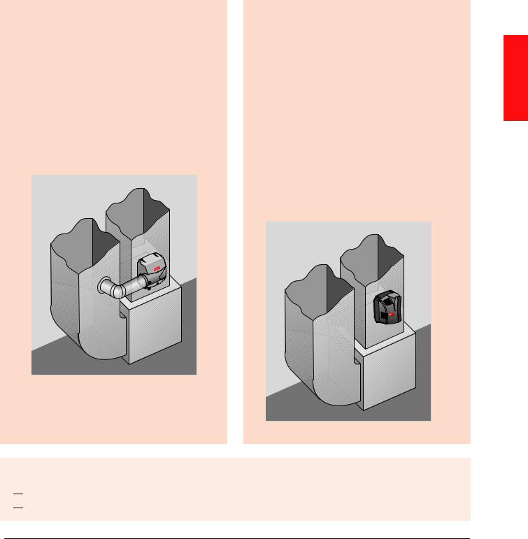
Choosing a Mounting Method
Whether you purchased a Bypass or Fan humidifier will determine how your humidifier will be installed:
Which humidifier do you have?
Bypass:
Bypass humidifiers use the pressure difference between the supply and return to move duct air through the humidifier. Access to both the supply and return are required. The bypass humidifier can be positioned on either the supply or return duct.
Fan:
Fan humidifiers use an internal fan to move duct air through the humidifier pad and back into the duct for distribution throughout your home. The fan model is commonly installed directly onto the supply (hot) air duct of your HVAC system.
The fan model can be installed on the return
(cool) air duct, if the location permits. When a return-side installation is used, it is highly recommended to plumb warm water since humidity is produced by evaporation.
MCR29871
MCR29929
Before beginning Mounting:

 I have confirmed local codes for proper plumbing practices.

 I have chosen an installation location that meets the requirements on page 4.
MOUNTING
Humidifier 69-2413EF—17 |
5 |

MOUNTING
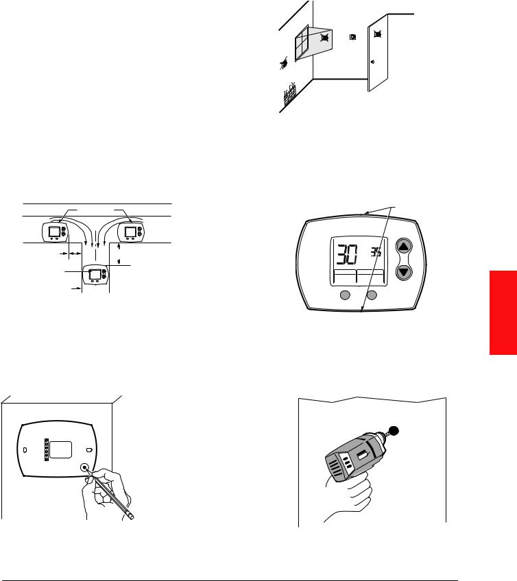
STEP ONE: Select the Mounting Location
1
2 |
3 |
|
2 |
||
|
4
MCR29877
Choose a location that has access to a water supply pipe. Cold or hot water can be used.
Select a vertical or horizontal surface on the HVAC duct work, with adequate space clearances, where the humidifier can be mounted.
Location must also have access to 120 VAC power. For the HE300 Fan humidifier, the power cord is 6 feet long.
Ensure the location is near a drain. Consult local plumbing codes for proper drainage. If no main floor drain is available, see “Appendix C: Advanced Draining.”
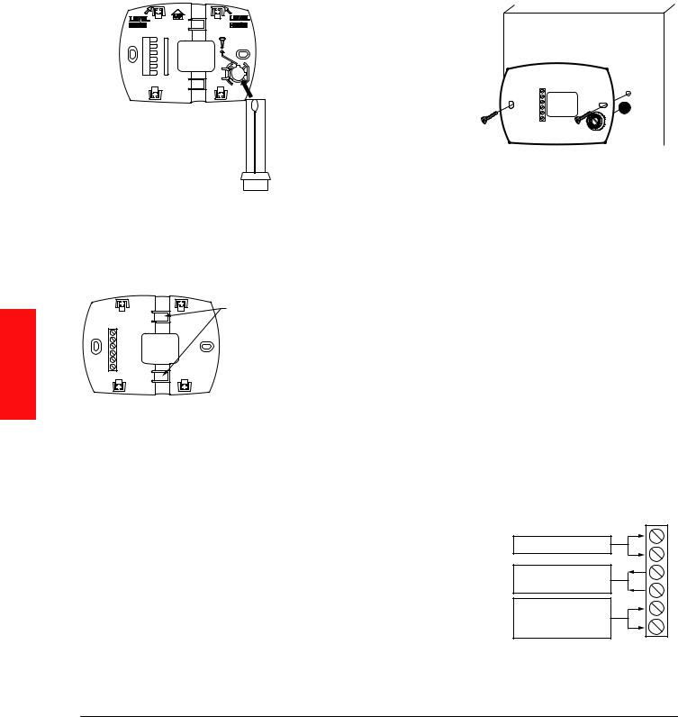
STEP TWO: Install MountingTemplate to the Duct
|
1 |
|
|
M32930 |
|
|
FAN |
1-3/4 |
|
(44) |
|
|
|
|
|
BYPASS |
|
|
|
1/2 |
|
2 |
(13) |
3 |
|
|
M29873 |
A-COIL |
|
|
|
|
|
|
M29874 |
Position the template on the duct.
•Make sure the template is level and in the desired position on the duct. Peel adhesive backing
and press template firmly into place in desired mounting location.
Ensure proper clearances from the air-conditioning coil inside the duct.
NOTE: The HE300 Fan model extends into the duct 1-3/4 inch. Bypass models extend into the duct 1/2 inch. Ensure clearance inside the duct.
•For best performance, maintain at least 24 inches downstream of open air space inside the duct.
Cut the sheet metal, following the template outline.
6 |
Humidifier 69-2413EF—17 |
If you are installing HE300 Fan model, proceed to page 10.
Bypass Model Installation
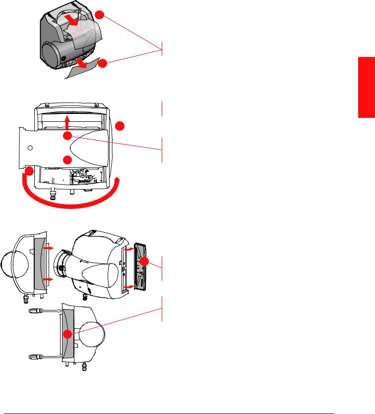
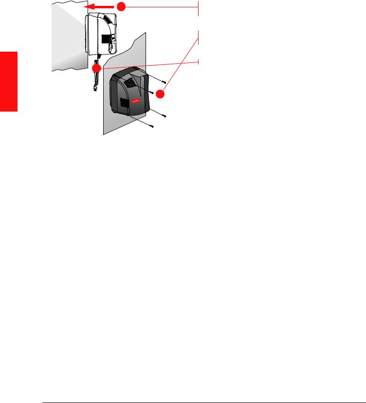
STEPTHREE: Configure Humidifier Bypass
1 |
Configure the humidifier bypass outlet to the side that |
|
best fits the application. |
|
If the bypass needs to be on the other side, remove |
|
the top and bottom covers. |
1 |
|
2 
3
3 
2 

Unplug the damper wire and plug in on the other side
(HE150/HE250 only).
Pull the bypass clamps apart from center to remove the bypass; snap it back into place with the outlet on the desired side.
MCR29876 |
Ensure that the pad is accessible. The handle of the |
|
|
|
pad holder and side panel of the humidifier can be |
|
switched so the pad holder can be removed (opposite |
|
side of the bypass duct opening). |
4 |
To remove the handle for the pad holder, slide it |
|
toward the back of the humidifier, then pull it away |
|
from the humidifier. |
|
To remove the opposite side panel, place a |
|
screwdriver into the two slots on the back of the |
|
humidifier, and pop the panel off. |
5 |
Snap the pad holder handle and side panel back into |
|
|
|
place in the desired configuration. |
MCR29946 |
|
MOUNTING
Humidifier 69-2413EF—17 |
7 |
MOUNTING
Bypass Model Installation
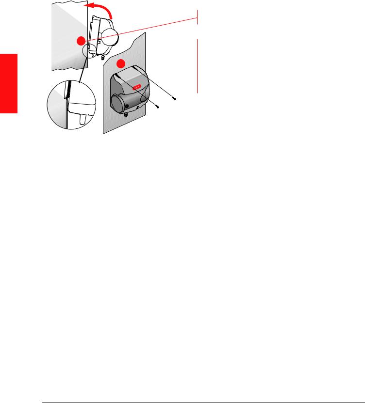
STEP FOUR: Mounting
1
2 
MCR29870
Secure the support hooks on Bypass models to the bottom lip of the hole.
Push the top of the humidifier back against the duct.
Verify the humidifier is level and fasten the humidifier to the duct using two self-drilling sheet metal screws provided.
8 |
Humidifier 69-2413EF—17 |
Bypass Model Installation
STEP FIVE: Bypass Duct Installation
1
2 
On the duct opposite the humidifier Bypass install, cut a 6-in. diameter duct hole.
•If the humidifier is on the supply duct, the 6-in. diameter hole should be on the return.
•If the humidifier is on the return duct, the 6-in. diameter hole should be on the supply.
Secure a 6-in. round duct starter collar into the 6-in. duct hole.
MCR29933
2
 1
1 


2 MCR29878
Use rigid or aluminized flexible 6-in. duct to connect the starter collar to the humidifier bypass port.
Secure the duct to the humidifier port with self-drilling sheet metal screws using the pre-drilled holes on the bypass port. For added seal, wrap sheet metal tape around the duct to port connection point.
Bypass mounting is complete. Go to page 15.
Before proceeding to the next step:

 I secured the humidifier to the duct as instructed.
MOUNTING
Humidifier 69-2413EF—17 |
9 |
MOUNTING
Fan Model Installation
STEPTHREE: Mounting
1
3
2
MCR29934
Slide the Fan model evenly into the duct hole. Verify the humidifier is level.
Fasten the humidifier to the duct using four self-drilling sheet metal screws provided.
Do not plug the humidifier in yet.
10 |
Humidifier 69-2413EF—17 |
Water Supply and Drain Connections
STEP ONE: Connect the Water Supply
1 
2
 3
3
MCR32931A
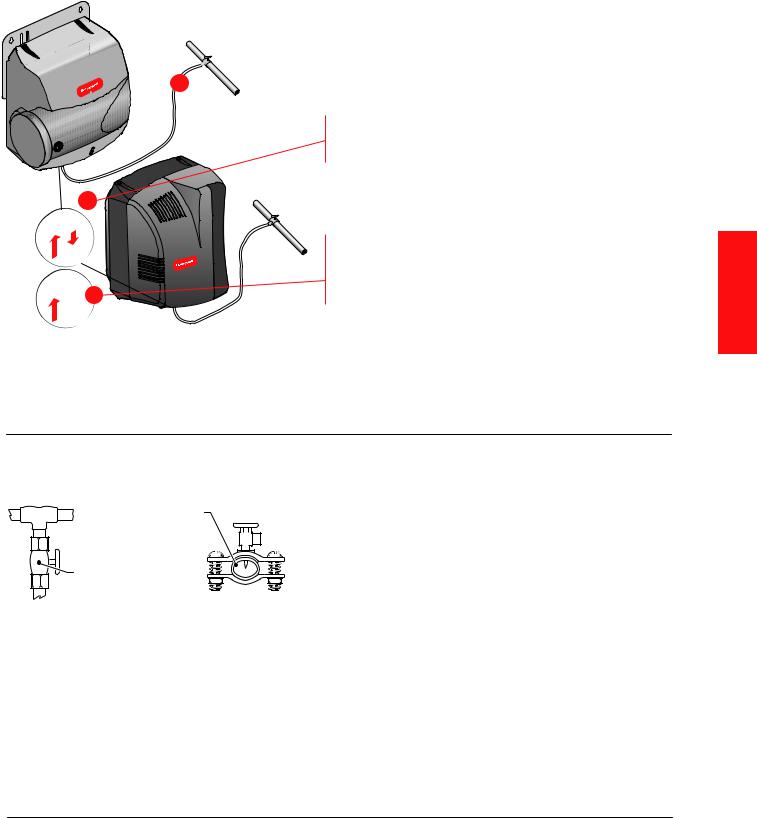
STEP TWO: Tap into a Water Line
|
Water Supply |
|
Line |
|
Manual Shutoff |
|
Valve |
T-fitting |
Saddle Valve |
|
M29605 |
Use hot or cold water.
Cut the water line so it reaches from the humidifier to the main water supply tap.
Insert the water line into the gray quick connect fitting. Insert it fully, and apply modest pull pressure to ensure a tight fit.
Note: The quick connect fitting can be removed if you prefer to use a standard 1/4-in. brass compression nut plumbing connection. Do not remove the filter if you select this option.
•Consult local codes for proper plumbing.
•Use the saddle valve provided or a T-fitting and manual shutoff valve to tap into the water line.
•Refer to the literature included with the valve you chose and the local plumbing codes. Use proper technique for the valve.
•Connect the other end of the humidifier water line to the water valve.
PLUMBING
Humidifier 69-2413EF—17 |
11 |
PLUMBING
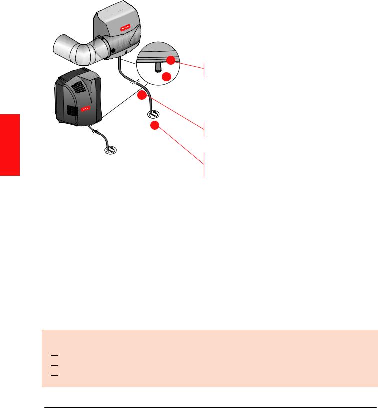
STEPTHREE: Connect to the Water Drain
1

 2 3
2 3 
4
MCR29881
•Consult and follow local plumbing codes for drain pipe size and flow requirement.
•The ideal installation is directly to the main floor drain using the rubber hose provided.
•If direct floor drain access is not available, see “Appendix C: Advanced Draining.”
Connect the 1/2-in. drain hose provided to the drain fitting on the bottom of the humidifier.
Use the hose clamp provided to secure the drain hose to the fitting.
Route the drain hose to the floor drain. The hose must have a continuous downward slope.
Direct the hose outlet into the floor drain. Secure the hose to reduce the risk of water pooling or splashing as it drains from the humidifier.
Before proceeding to Wiring:

 I have connected the water supply line to the humidifier and the main water tap.

 I have installed the drain connection.

 I have checked all plumbing connections for leaks.
12 |
Humidifier 69-2413EF—17 |
Before Wiring the Humidifier
CAUTION:Voltage Hazard.
Be sure the humidifier is not plugged in before beginning wiring.
Before wiring the humidifier:

 I understand and will comply with applicable local wiring codes and regulations.
 I will read the section “Using the DIP Switches” beginning on the next page.
What humidifier model do I have?
The model number can be found on the bottom of the humidifier.
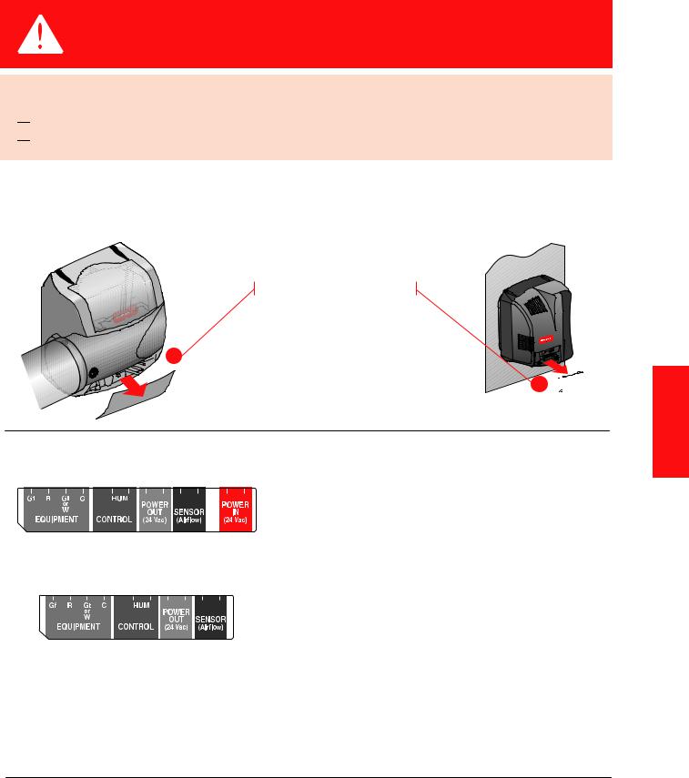
STEP ONE: Remove the Humidifier Cover
Remove the bottom cover.

 1a
1a
1b 
MCR29950
MCR29935
STEP TWO: Understand the WiringTerminals (HE150/HE250/HE300 only)
HE150/HE250 Bypass Terminal
MCR29937
HE300 Fan Terminal
M29936
Gf: Used to force system fan on when humidity is needed.
R: Input from system R. Needed to power Gf when forcing fan on.
Gt or W: Input from system G or W. Needed to humidify only during fan or heat calls by system. HUM: Powered contacts for humidity control.
C: Common. Needed for Gt or W input. Connect to system C.
Power Out: 24V power for electric controls. Power In: Power from 15VA transformer on HE150/ HE250 only.
SENSOR: Powered contacts for an air proving device when utilized.
WIRING
Humidifier 69-2413EF—17 |
13 |

WIRING
Using the DIP Switches (HE150/HE250/HE300 only)
Two features are configured by DIP settings, which are described inside the humidifier cover.
STEPTHREE: Understand the DIP Switches
MCR29882
DIP 1 (Top): This switch looks for inputs from the
HVAC system before allowing humidity. Set to the left, the humidifier will look for input(s). Set to the right, it will not.
DIP 2 (Bottom): This switch controls the fan. Set to the left, the HVAC system controls the fan. Set to the right, the humidifier will force the fan on when there is a call for humidity.
STEP FOUR: Install theTransformer (Bypass Models Only)
Install transformer on the outside of a grounded metal junction box using only a 7/8 in. (22 mm) knockout hole. Place mounting tabs into the knockout hole and firmly tighten the locking screw. Field wiring connections and grounding means for the transformer and enclosure shall be in accordance with the National Electrical Code
(NEC) and the Canadian Electrical Code (CEC). Connect wires to the 120V side of the transformer.
For HE150 and HE250, the 15V transformer must provide constant power to the 24V IN terminals.
STEP FIVE: Wiring the Humidifier
Use a wiring diagram from the following pages that matches your equipment.
When wiring is complete, run the wires coming out of the humidifier into the wiring clip on the bottom of the humidifier.
14 |
Humidifier 69-2413EF—17 |
Installing the Humidistat
Remote Mount Installation
Choose a location in the living area.
NOTE: Select a location clear of drafts or excessive humidity. Avoid mounting near doors or windows, or in bathrooms or kitchens.
OR
NO
YES
M
Duct-Mount Installation (recommended)
1. Choose a location on the RETURN duct. |
2. Separate wallplate from humidistat. |
|
ALTERNATE |
|
05,, (%2% |
LOCATION |
|
|
RETURN |
RETURN |
|
AIR |
AIR |
|
|
)NSIDE |
2EPLACE"ATT |
3ETTING |
||
|
|
|
|
||
|
15 IN (381 MM) |
|
|
|
|
6 IN (152 MM) |
|
|
|
||
MINIMUM |
|
|
|
|
|
MINIMUM |
|
|
|
|
|
|
|
|
|
|
|
|
(5-)$)49 "//34 |
|
|
|
|
BEST |
|
,IGHT |
3YSTEM |
|
|
LOCATION |
|
!UTO |
.EXT!UTO |
|
|
RETURN |
|
|
|
|
|
AIR DUCT |
M34579 |
|
|
|
|
Warning: Product must be mounted on the RETURN side of the duct for proper RH% sensing.
3. Mark the duct-tube hole.
-
Caution: Electrical Hazard
Can cause electrical shock or equipment damage. Disconnect power before beginning installation.
4. Drill the duct-tube hole.
WIRING
M34580
Hold the wallplate up to the desired location on the duct and make a mark inside the duct tube hole.
M34581
Find your mark and drill a 1/2 in. hole in the duct. This is where the duct tube will be inserted to capture air.
Humidifier 69-2413EF—17 |
15 |
WIRING
Installing the Humidistat
Duct-Mount Installation (continued)
5. Insert the duct tube.
Insert the duct tube through the wallplate before securing to the duct.
M34671
7. Run wires through the back plate.
6. Secure the wallplate.
M34582
Secure the wallplate to the duct with sheet metal screws (provided).
|
RUN WIRES |
|
THROUGH THE |
C |
TOP OR BOTTOM |
CHANNEL |
|
R |
|
U |
|
U |
|
S |
|
S |
|
|
M34610 |
Run wires through the top or bottom channel on the back plate when duct-mounted. If installing like a thermostat on a wall, run the wires through the back.
Wiring the Humidistat
This humidity control is wired the same way a manual humidistat (H8908) is wired. The only difference is that you also wire in power (24 VAC) and an outdoor sensor.
TERMINAL DESIGNATION
C 24 VAC POWER FROM EQUIPMENT
R24 VAC POWER FROM EQUIPMENT
UHUMIDIFIER
UHUMIDIFIER
SOUTDOOR SENSOR
S OUTDOOR SENSOR
24 VAC (CONSTANT)
TO HUMIDIFIER
OUTDOOR TEMPERATURE SENSOR
NOTES: C AND R MUST BE CONSTANT 24VAC! RECOMMENDED TO WIRE TO FURNACE/AIR HANDLER CONTROL BOARD.
DO NOT WIRE C AND R TO HUMIDIFIER TRANSFORMER!
C
R
U
U
S
S
M34865
16 |
Humidifier 69-2413EF—17 |
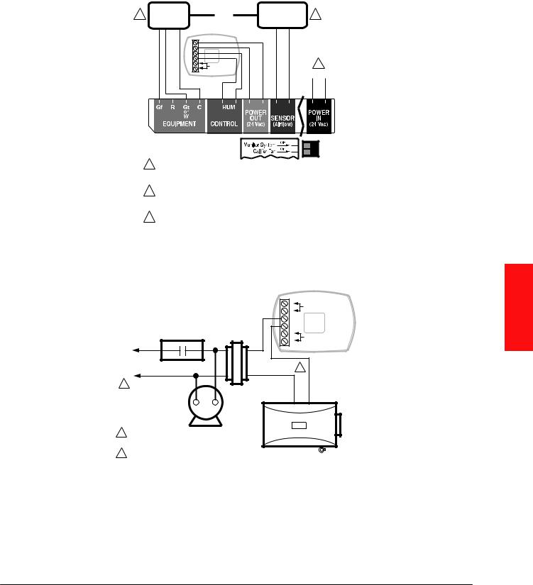
Wiring Configuration: Advanced Models (HE150/HE250/HE300)
Wiring HumidiPRO toTrueEASE Advanced Humidifier with Fan Interlock (HE150/HE250/HE300).
2 |
G OR W |
|
OR |
AIR PROVING |
3 |
|
C |
|
DEVICE |
|
|||
|
|
|
|
|
||
|
|
|
|
|
|
|
|
|
|
HumidiPRO |
|
|
|
|
|
C |
|
|
|
|
|
|
R |
|
|
|
|
|
|
U |
|
|
|
|
|
|
U |
|
|
|
|
|
|
S |
OUTDOOR |
|
|
1 |
|
|
S |
|
|
||
|
|
SENSOR |
|
POWER IN |
||
|
|
|
|
|||
|
|
|
|
|
||
LEFT
LEFT
1HE150/HE250 USES A 15 VA TRANSFORMER WIRED INTO 24V IN. HE100/HE200 USES A 10 VA TRANSFORMER WIRED INTO 24V IN. HE300 USES A LINE CORD PLUG.
2CONNECT G TO HUMIDIFY WHEN THERE IS A FAN CALL. CONNECT W TO HUMIDIFY WHEN THERE IS A HEAT CALL. NEVER CONNECT BOTH. CONNECT C WHEN USING G OR W.
3USE AIR PROVING DEVICE INSTEAD OF THE G/W CONNECTION
TO HUMIDIFY ANY TIME THE FAN IS OPERATING. |
M35152 |
|
Wiring Configuration: Basic Models (HE100/HE200)
Wiring HumidiPRO toTrueEASE Basic Humidifier with Fan Interlock (HE100/HE200).
FAN CONTROL |
TRANSFORMER |
L1
(HOT) POWER SUPPLY
L2
1FURNACE FAN
MOTOR
1PROVIDE DISCONNECT MEANS AND OVERLOAD PROTECTION AS REQUIRED.
224 VAC WIRING.
C |
24V CONSTANT |
|
R |
REQUIRED |
|
|
||
U |
|
|
U |
|
|
S |
OUTDOOR SENSOR |
|
S |
||
|
2
HUMIDIFIER
M34570A
Advanced Wiring Diagrams are shown in Appendix B beginning on page 27.
WIRING
Humidifier 69-2413EF—17 |
17 |
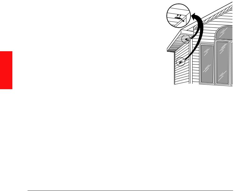
Mounting the Outdoor Sensor
(Not required if window protection isn’t needed)
Location
Mount the sensor where:
•it cannot be tampered with.
•there is good air circulation.
•surface is flat.
•wire distance between sensor and humidistat is less than 200 feet.
•it can measure true outdoor ambient temperature.
Do NOT mount the sensor:
•in direct sunlight.
•where snow, ice or debris can cover it.
•where hot or cold air blows on the sensor. (For example, a discharge line from an outdoor compressor unit, vent or fan can cause inaccurate temperature readings.)
Steps to mount the sensor
1. Remove the sensor from the mounting clip.
2. Mark the area on the location selected for mounting the sensor mounting clip. 3. Mount the clip. Image on right shows typical locations for outdoor sensor.
WIRING
M7514A
18 |
Humidifier 69-2413EF—17 |
Wiring the Outdoor Sensor
CAUTION: Electrical Interference (Noise) Hazard. Can cause erratic system operation.
Keep wiring at least one foot away from large inductive loads such as motors, line starters, lighting ballasts and large power distribution panels.
Use shielded cable to reduce interference when rerouting is not possible. Be sure wires have a cable separate from the thermostat cable.
Do not route temperature sensor wiring with building power wiring, next to control contactors or near light dimming circuits, electric motors or welding equipment.
Avoid poor wiring connections.
Avoid intermittent or missing building earth ground.
CAUTION: Electrical Shock Hazard. Can cause electrical shock or equipment damage.
Disconnect power supply before connecting wiring.
Wiring must comply with applicable codes, ordinances and regulations:
1.Wire the C7089 Outdoor Sensor to the S terminals on the humidity control. If leadwire provided with C7089 is not long enough (60 in.), run a cable to a hole at C7089 location.
•Using color-coded, 18-gauge, shielded thermostat wire is recommended. For example of general wiring of C7089, see image at right.
•Pigtail wiring can be used.
2.Mount C7089 in its mounting clip.
3.Plug wiring hole using nonhardening caulk or putty.
1 |
WIRING HOLE |
|
|
C7089 |
THROUGH 2 |
|
STRUCTURE |
C
R
U
U
S
S
1USE APPROPRIATE MOUNTING MEANS FOR THE TYPE OF STRUCTURE.
2PLUG WIRING HOLE WITH NON-HARDENING
CAULK OR PUTTY. |
M34611 |
WIRING
Humidifier 69-2413EF—17 |
19 |
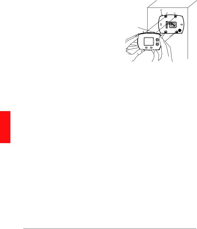
Mount Humidity Control
Align the 4 tabs on the wallplate with the slots on the back of the control, then push gently until the control snaps in place.
WALLPLATE
TABS
SLOTS ON
BACK OF
HumidiPRO
M34583
Checkout
Allow C7089B Outdoor Sensor to absorb outdoor air for a minimum of twenty minutes before taking a reading. With an accurate thermometer (±1°F [0.5°C]), measure the temperature at the sensor location, allowing time for the thermometer to stabilize before reading.
Then verify the sensor accuracy by going into installer Test #20. This will show you the outdoor temperature.
Calibration
The C7089 Outdoor Sensor is calibrated at the factory. However, you can offset the outdoor sensor reading using Function 35 in Installer Setup.
WIRING
You’ve just installed your Humidity Controller!
This Humidity Control has been preprogrammed to the ideal settings for most homes.
If you installed this control with an outdoor sensor, the control will operate in AUTOMATIC MODE, which automatically adjusts humidity to help prevent window condensation.
If you installed this control without an outdoor sensor, the control will operate in MANUAL MODE, giving the homeowner simple, direct control of their humidifier (RH% Setting Only).
Advanced Installer Setup
See next page to customize feature operation.
Installer System Test
If Advanced Installer Setup is not required, skip to “Installer System Test/Checkout” on page 22.
20 |
Humidifier 69-2413EF—17 |
 Loading...