


H8908A/B Humidistat;
H8908C/D Dehumidistat
APPLICATION
The H8908 family of low-voltage humidistats/ dehumidistats provide accurate control of whole house humidifiers, dehumidifiers, and ventilators. They have a snap-acting, dust-proof SPST switch and can be mounted to a duct or wall.
Before Installing this Product...
1.Read these instructions carefully. Failure to follow them could damage the product or cause a hazardous condition.
2.Check the ratings given in the instructions and on the product to make sure the product is suitable for your application.
3.Installer must be a trained, experienced service technician.
 CAUTION
Personal Injury Hazard.
Power supply can cause electrical shock.
Disconnect power supply before beginning installation.
NOTE: The H8908 electrical connections are not shared with the thermostat.
INSTALLATION INSTRUCTIONS
M24726
Fig. 1. H8908A,D control.
|
|
|
OUTDOOR |
HUMIDITY |
|
|
|
|
TEMPERATURE |
SETTING |
|
|
|
|
-20 F |
-30 C |
15% |
Humidity |
|
|
-10 F |
-25 C |
|
Control |
0 F |
-20 C |
25% |
||
|
+10 F |
-10 C |
|||
Régulateur |
d'humidité |
+20 F |
-5 C |
35% |
|
|
|
Over 20 F |
Over 0 C |
||
|
|
|
|
40% |
|
HOLE FOR WIRING |
CASE REMOVAL |
THE DUCT MOUNTING |
SLOT |
INSTALLATIONS |
M13371 |
Fig. 2. H8908B,C control.
Place Bar Code Here
69-1341EF-07
H8908A/B HUMIDISTAT; H8908C/D DEHUMIDISTAT
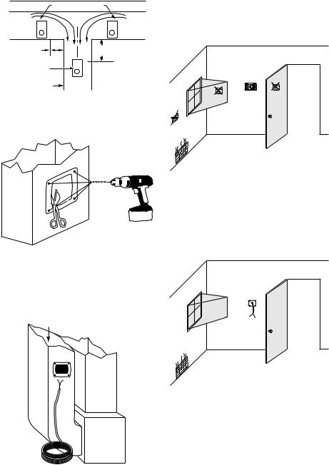
DUCT INSTALLATION
1.Choose a location on the duct.
|
ALTERNATE LOCATION |
RETURN |
RETURN |
AIR |
AIR |
6 in. (152 mm) |
15 in. (381 mm) |
MINIMUM |
|
|
MINIMUM |
BEST |
|
LOCATION |
|
RETURN AIR DUCT |
M13369 |
|
Fig. 3. Duct installation locations.
2.Apply sticker template to duct and drill holes for mounting screws. Cut along the dotted line of the template with metal shears or tin snips.
M24800
Fig. 4. Drill and cut holes in duct.
3.Run two-fan, low-voltage wire to the mounting location on the duct. See Fig. 5.
IMPORTANT
Use rated 18-22 gauge wire. Leave approximately 6 in. of wire to properly connect the humidistat.
RETURN
SUPPLY
REMOTE MOUNT
INSTALLATION
1. Choose a location in the living area.
NOTE: Select a location clear of drafts or excessive humidity. Avoid mounting near doors or windows, or in bathrooms or kitchens. See Fig. 6.
M24718
Fig. 6. Choose a location in the living area.
2.Cut 1 in. diameter wire hole in wall.
3.Run two-fan, low-voltage wire to the mounting location in the living area.
IMPORTANT
Use rated 18-22 gauge wire. Leave approximately 6 in. of wire to properly connect the humidistat.
M24721
Fig. 7. Run wire to the mounting location.
TWO-FAN 18-22 GAUGE WIRE |
M24720 |
Fig. 5. Run wire to the mounting location.
69-1341EF—07 |
2 |
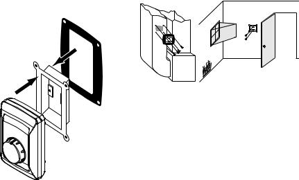
4.Remove the base bracket from the humidistat. For duct mount, slide the black gasket onto the base bracket. See Fig. 8.
NOTE: Use gasket only when mounting the control to ductwork. Leave off when mounting to a wall.
H8908A/B HUMIDISTAT; H8908C/D DEHUMIDISTAT
5.Secure the base bracket to the duct or remote location. Secure to the duct with four 1-in. (25 mm) screws (provided) or to the wall with two 1-in. (25 mm) screws (provided).
M24722
Fig. 9. Mount base bracket to duct or remote location.
M24733
Fig. 8. Seal base bracket.
3 |
69-1341EF—07 |
H8908A/B HUMIDISTAT; H8908C/D DEHUMIDISTAT
WIRING
 CAUTION
Personal Injury Hazard.
Can cause electrical shock and injury.
Disconnect power before installation or servicing.
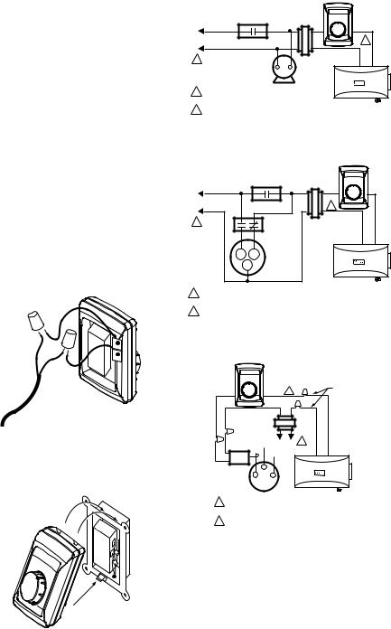
All wiring must comply with applicable local codes, ordinances and regulations. Make wiring connections according to humidifier (or dehumidifier/ventilator) instructions, if available; otherwise, see typical wiring diagrams in Fig. 12–19.
IMPORTANT
Select models of fan centers include humidifier taps so the current sensing relay, sail switch or air pressure switch is not needed. If not using a current sensing relay, sail switch, or air pressure switch, the humidifier must be energized during blower motor cycles for proper operation.
On multispeed blower applications, do not wire the high voltage side of the transformer to the same power source that services the furnace blower. Premature transformer burnout can occur. On HE365 fan powered humidifier models, only the two yellow wires are connected to the control. The remaining two red wires are only used with electronic humidity controls.
6.Using wire nuts, connect the low-voltage wire to the leads on the H8908 humidistat. See Fig. 6–19 for different wiring configurations.
M24734
Fig. 10. Wire the humidistat.
7.Mount the humidistat by hooking the two hinges at the top of the back cover to the raised edge at the top of the base bracket. Press the bottom of the humidistat in to engage the base hinge. You will hear a “click” when the humidistat is secured.
M24801
Fig. 11. Attach the humidistat to the base.
|
|
H8908 |
|
|
|
30 |
40 |
|
|
20 |
50 |
L1 |
POWER |
10 |
60 |
(HOT) |
OFF |
ON |
|
|
SUPPLY |
FAN CONTROL |
2 |
L2 |
|
|
|
1 |
|
TRANSFORMER |
|
|
|
FURNACE |
|
|
|
FAN |
|
|
|
MOTOR |
|
1 PROVIDE DISCONNECT MEANS AND |
|
||
|
OVERLOAD PROTECTION AS REQUIRED. |
|
|
2 |
|
HUMIDIFIER |
|
24 VAC WIRING. |
|
||
M24727
Fig. 12. Wiring H8908 with fan interlock.
H8908
L1 |
|
|
|
|
(HOT) |
POWER |
FAN CONTROL |
||
|
SUPPLY |
|||
L2 |
|
|
|
|
1 |
|
|
|
DPST |
|
|
|
SWITCHING |
|
|
|
|
|
|
|
|
|
|
RELAY |
|
H |
|
L |
2-SPEED |
|
|
FAN |
||
|
|
|
|
|
|
|
C |
|
MOTOR |
|
|
|
|
|
30 |
40 |
20 |
50 |
10 |
60 |
OFF |
ON |
2 |
|
TRANSFORMER
HUMIDIFIER
1POWER SUPPLY. PROVIDE DISCONNECT MEANS AND OVERLOAD PROTECTION AS REQUIRED.
M24728
2 24 VAC WIRING.
Fig. 13. Wiring H8908 with 2-speed fan motor.
H8908
30 |
40 |
|
|
WATER |
20 |
|
50 |
|
|
10 |
|
60 |
2 |
SOLENOID |
OFF |
ON |
|
|
LEAD WIRE |
TRANSFORMER |
|
|
||
|
|
L2 |
L1 |
1 |
|
|
|
(HOT) |
|
CURRENT |
|
LO |
|
|
SENSING |
|
|
|
|
RELAY |
C |
HI |
|
|
HUMIDIFIER 
1POWER SUPPLY. PROVIDE DISCONNECT MEANS AND OVERLOAD PROTECTION AS REQUIRED.
2 24V WIRING. |
M24729 |
Fig. 14. Typical wiring diagram of current sensing relay with humidifier.
69-1341EF—07 |
4 |

H8908A/B HUMIDISTAT; H8908C/D DEHUMIDISTAT
H8908 |
H8908 |
AIR |
|
|
|
|
|
|
|
|
PRESSURE SWITCH/ |
30 |
40 |
|
30 |
40 |
FAN WIRING |
|
|
SAIL SWITCH |
20 |
50 |
|
20 |
50 |
TERMINALS |
|
|
|
10 |
60 |
|
10 |
60 |
1 |
1 |
TO |
2 |
OFF |
ON |
|
OFF |
ON |
|||
|
|
|
|
|
|
|
SYSTEM |
|
|
|
|
|
|
|
|
|
FAN |
TRANSFORMER |
|
|
|
|
HUMIDISTAT |
|
|
|
|
|
|
|
TERMINALS |
HUMIDIFIER |
|
||
|
|
|
|
|
|
|
|
|
|
1 |
|
1 |
24V WIRING. |
|
|
||
|
L2 |
L1 |
|
|
NOTE: FOLLOW THE INSTALLATION INSTRUCTIONS |
|
|
|
|
(HOT) |
|
|
|
||
|
|
HUMIDIFIER |
INCLUDED WITH THE STEAM HUMIDIFIER |
|
|||
|
|
|
|
||||
1 |
|
|
TO WIRE THE SYSTEM FAN. |
M24731 |
|||
POWER SUPPLY. PROVIDE DISCONNECT MEANS |
|||||||
|
|
||||||
|
AND OVERLOAD PROTECTION AS REQUIRED. |
Fig. 16. Wiring H8908 with steam humidifiers. |
|||||
2 |
24V WIRING. |
|
M24730B |
||||
|
|
|
|||||
|
Fig. 15. Wiring H8908 in line with |
|
|
||||
air pressure switch/sail switch and humidifier. |
|
|
|||||
|
TH9421 VISION PRO |
|
|
EQUIPMENT INTERFACE MODULE |
|
||
|
THERMOSTAT |
|
|
|
|||
|
|
|
1 |
|
|
1 |
|
CONV. |
HP |
STAGE 1 |
|
|
|
|
|
|
W1 |
O/B |
HEAT |
||
|
|
|
2 |
|
|
2 |
|
|||
|
|
|
|
|
|
W2 |
AUX |
|
||
|
|
|
3 |
|
|
3 |
|
|
||
|
|
|
L2 |
C |
|
W3 |
AUX2 |
|
||
|
|
|
|
C |
|
STAGE 2 |
||||
|
|
|
|
|
Y |
Y |
||||
|
|
|
|
|
|
24 VAC |
||||
|
|
|
|
SYSTEM |
|
R |
HEAT |
|||
|
|
|
|
|
Y2 |
Y2 |
||||
|
|
|
TRANSFORMER |
|
|
|
||||
|
|
|
|
RC |
|
|
||||
|
|
|
|
L1 |
R |
|
G |
G |
|
|
|
|
|
|
|
|
RH |
|
|
|
COMPRESSOR |
|
|
|
|
|
|
|
|
|
|
|
H8908B |
|
L2 |
C |
|
H1 |
|
L |
|
|
|
|
|
24 VOLT |
|
|
U |
|
NOT USED |
|
||
|
TRANSFORMER |
|
|
M2 |
|
OUT1 |
|
|||
|
R |
|
D1 |
|
FAN |
|||||
|
|
|
L1 |
|
|
|||||
|
|
|
|
H |
OR |
OUT2 |
||||
|
|
|
|
|
|
RELAY |
||||
|
|
|
|
|
|
M2 |
|
|||
30 |
40 |
|
|
|
|
|
IN1 |
|
|
|
|
|
|
|
|
|
V1 |
|
|
|
|
20 |
50 |
|
|
|
|
N |
|
IN2 |
|
|
|
|
|
|
|
|
|
|
|
||
|
|
|
|
|
|
T2 |
|
|
|
|
10 |
60 |
|
|
|
|
|
|
|
|
|
OFF |
ON |
|
|
|
|
|
|
DATS1 |
|
|
|
|
|
|
|
|
|
|
C7089U1006 |
||
|
|
|
|
|
|
|
|
|
|
|
|
|
|
|
|
|
|
|
DATS2 |
|
|
|
COM |
N.O. |
N.C. |
|
|
|
|
|
|
|
S688 AIR |
|
PRESSURE |
HE225/HE265 |
SWITCH/ |
HUMIDIFIER |
SAIL SWITCH |
M24724B |
Fig. 17. Wiring H8908 with VisionPRO® IAQ on typical 2-stage furnace.
VISIONPRO® THERMOSTAT |
H8908D |
Y2 |
RC |
|
|
L |
R |
|
|
A |
W |
|
|
W2 |
Y |
|
|
S1 |
G |
|
|
S2 |
C |
H8908D |
|
|
|
||
HEATING |
|
30 |
40 |
|
|
|
|
RELAY OR |
|
20 |
50 |
|
|
|
|
VALVE COIL |
|
10 |
60 |
|
|
OFF |
ON |
COOLING |
FAN |
|
|
CONTACTOR |
RELAY |
|
|
COIL |
COIL |
|
|
|
|
1 |
|
30 |
40 |
VENTILATOR/DEHUMIDIFIER |
20 |
50 |
|
10 |
60 |
|
OFF |
ON |
|
|
|
TERMINALS |
|
|
Fresh Air Ventilation System |
|
|
Système de ventilation à air frais |
M24732
Fig. 19. Typical wiring diagram for HR150, HR200, ER150 and ER200 Ventilator or DH90 Dehumidifier applications.
1 PROVIDE OVERLOAD PROTECTION |
|
AND DISCONNECT MEANS AS REQUIRED. |
M24725 |
Fig. 18. Wiring H8908 with VisionPRO® Thermostat for dehumidification.
5 |
69-1341EF—07 |
 Loading...