


H7625B

INSTALLATION INSTRUCTIONS
63-2579—3
H7625B; H7635B,C; H7655B
Duct-Mount and Outdoor-Mount
Humidity/Temperature Sensors
APPLICATION
The H7625B, H7635B, H7655B Duct-Mount and H7635C
Outdoor-Mount Humidity/Temperature Sensors are
universal Relative Humidity transmitters that can be
powered with either a +18 to 36 Vdc or 24 Vac supply.
The sensors use a half-wave bridge rectifier to convert
AC power to a usable DC voltage. The device also
includes a 20K ohm temperature sensor for optional use.
The humidity sensors are designed with a field-
selectable 4to20 mA, 0to5Vdc, or 0to10Vdc output
signal equivalent to 0 to 100% RH. All units are shipped
from the factory with a default setting to accept AC power
with three-wire, 0 to 10 Vdc loop-powered output.
INSTALLATION
When Installing this Product...
1. Read these instructions carefully. Failure to follow
them could damage the product or cause a
hazardous condition.
2. Check ratings given in instructions and on the
product to ensure the product is suitable for your
application.
3. Installer must be a trained, experienced service
technician.
4. After installation is complete, check out product
operation as provided in these instructions.
CAUTION
Electrical Shock or Equipment Damage
Hazard.
Can shock individuals or short equipment
circuitry.
Disconnect power supply before installation.
CAUTION
Equipment Damage Hazard.
Improper wiring can damage the sensor
beyond repair.
Follow the wiring instructions carefully.
Mounting
The method of mounting depends on the particular
sensor application. The following procedures include
outdoor and duct applications. Also refer to the
instructions for the electronic control.
Duct Mounting
The H7625B, H7635B and H7655B can be mounted in a
duct to sense humidity and temperature.
IMPORTANT
Select a location to expose sensor to average
duct humidity and temperature. Avoid locations
where stratification can cause sensing errors.
NOTES:
— H7635C is weatherproof for outdoor use.
Knockouts allow 1/2 in. conduit connection.
— To avoid damaging board during installation,
the cover can be detached completely:
1.Carefully remove wire plug from board.
2.Set the cover aside.
1. Cut a hole in the duct just large enough to accept
the sensing element.
2. Open case by rotating the cover counterclockwise.
3. Mount standard 1/2 in. conduit to the case.
4. Use case to mark mounting screw pilot hole
locations.
5. Drill the pilot holes and fasten the sensor to the
duct.
6. Wire the sensor. See Wiring section.
NOTE: The two free wires are thermistor wiring
connections. When connecting these, use
two wire nuts.
7. Reattach the wire plug and cover being careful not
to pinch wires between the cover and case.
H7625B; H7635B,C; H7655B DUCT-MOUNT AND OUTDOOR-MOUNT HUMIDITY/TEMPERATURE SENSORS
63-2579—3 2
Outdoor Mounting
The H7635C senses outdoor air humidity and
temperature. Mount this control where it can sense
average outdoor air humidity and temperature. Normally,
the north side of a building provides a suitable location.
NOTES:
— H7635C is weatherproof for outdoor use.
Knockouts allow 1/2 in. conduit connection.
— To avoid damaging board during installation,
the cover can be detached completely:
1.Carefully remove wire plug from board.
2.Set the cover aside.
1. Open case by rotating the cover counterclockwise.
NOTE: Orient case so the element points down.
2. Mount standard 1/2 in. conduit to the case.
3. Use case to mark mounting screw pilot hole
locations.
4. Drill pilot holes.
5. Fasten the case to the wall.
6. Wire the sensor. See Wiring section.
NOTE: The two free wires are thermistor wiring
connections. When connecting these, use
two wire nuts.
7. Reattach the wire plug and cover being careful not
to pinch wires between the cover and case.
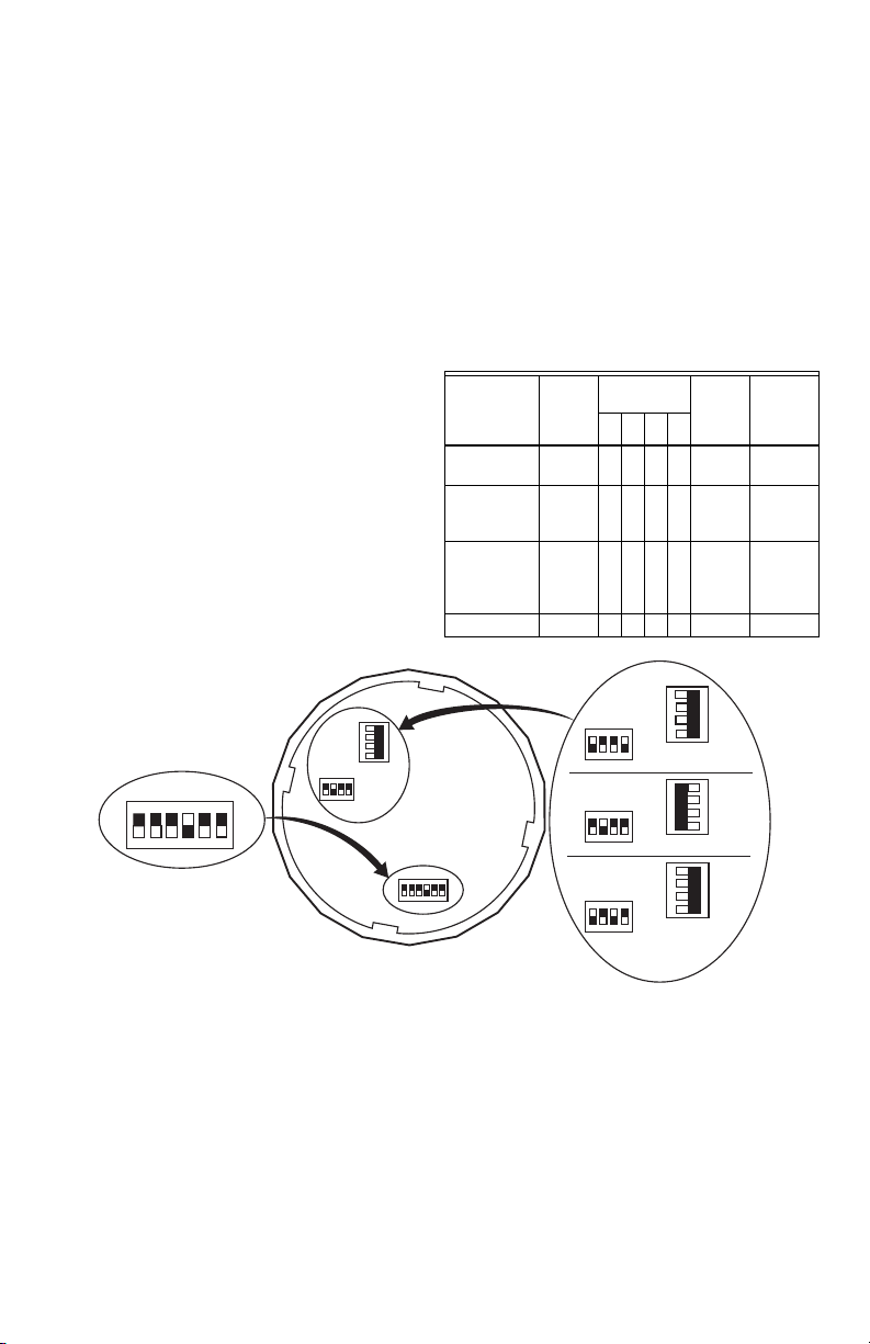
Output Settings (Table 1)
The board has three switch blocks:
— A six DIP switch block.
— A four DIP switch block.
— A white gang switch on a blue block.
1. Adjust the 4-switch block according to Table 1.
NOTE: The 6-switch block normally requires no
adjustment. (See the Appendix.)
2. Set the gang switch (white switch in blue block) to
correspond with the output (mA or Vdc).
NOTE: See Fig. 1 for DIP switch locations.
Table 1. Controller Compatibility
and Output Settings.
Fig. 1. DIP switch locations and settings.
Controller
Required
Sensor
Output
Setting
4-Switch Block
Settings
Blue and
White
Output
Switch
L
ONSPEC™
Setting4321
W7750, W7760,
W7761
4-20 mA — On — — 4-20 mA C7600C
W7750B,C
W7760C,
W7753, W7760
0-10 Vdc
(default)
On — — On Vout H7621/31
T7350, XL50,
XL100,
XL500 XF
Modules, XFL
0-10 Vdc
(default)
On — — On Vout n/a
Non-Honeywell 0-5 Vdc On — On — Vout n/a
M22705
NORMAL OPERATION
OFF
ON
OFF
ON
0-10 VDC
OFF
ON
4-20 MA
0-5 VDC
OFF
ON
H7625B; H7635B,C; H7655B DUCT-MOUNT AND OUTDOOR-MOUNT HUMIDITY/TEMPERATURE SENSORS
3 63-2579—3
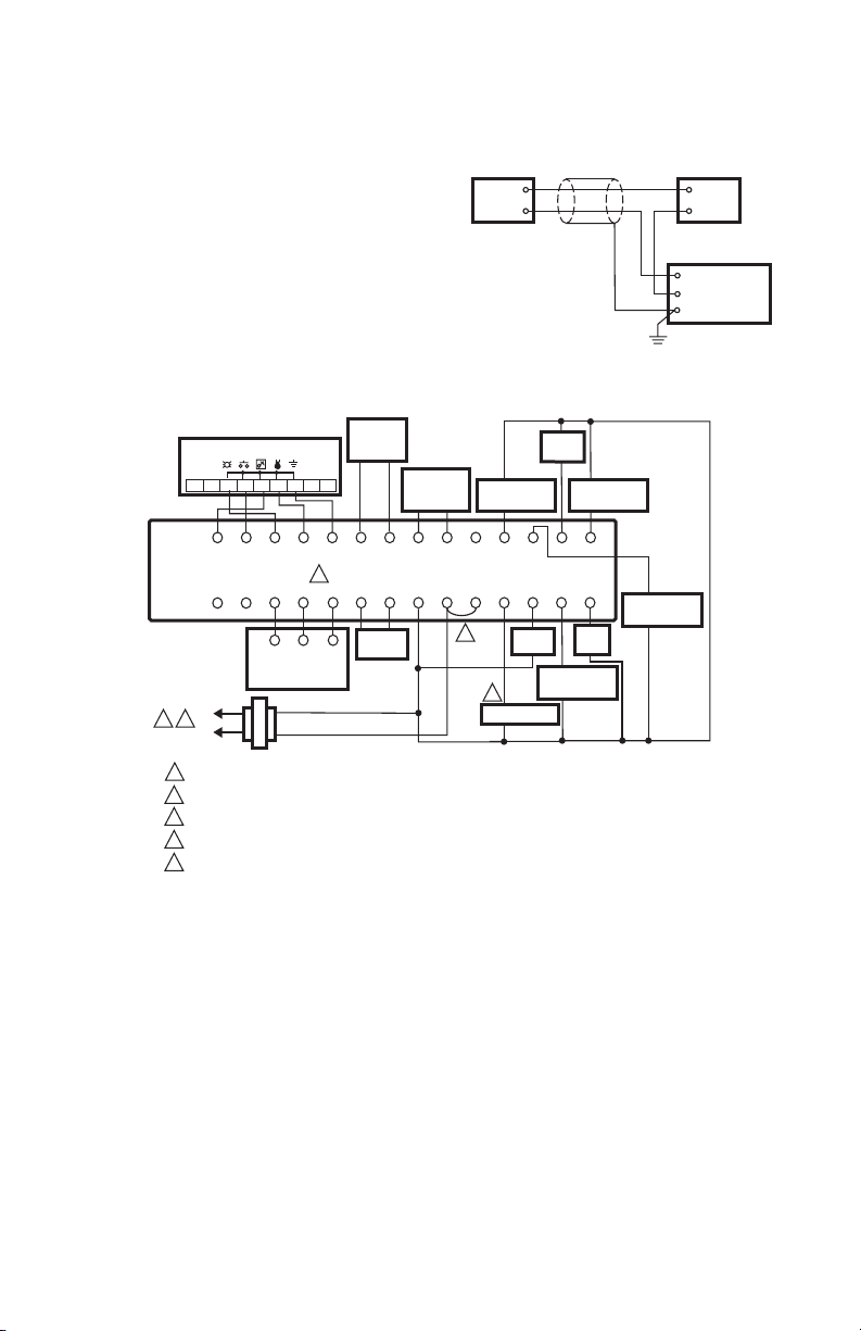
WIRING
For voltage output, shielded cable (16-22 AWG) should
be used.
For current output, either shielded cable or twisted pair
(16-22 AWG) can be used.
NOTE: When using shielded cable, ground the shield
only at the controller end (see Fig. 2). Grounding
both ends can cause a ground loop.
The 20K ohm NTC temperature output is accessed
through the separate blue and green wires (located inside
the enclosure).
Fig. 2. Typical wiring diagram for transducer with two-
wire mA output and external DC power supply.
Fig. 3. Humidity sensor (0-10 Vdc output) wiring with T7350
(use with RH/Temperature combination T7350 units only).
mA OUTPUT
TRANSDUCER
ONLY
18 TO 36 Vdc
POWER SUPPLY
CONTROLLER, METER
OR RECORDER
INPUT SIGNAL
COMMON
Vin +
+
Io –
–
M22528
GROUND
POWER SUPPLY. PROVIDE DISCONNECT MEANS AND OVERLOAD PROTECTION AS REQUIRED.
ENSURE TRANSFORMER IS SIZED TO HANDLE THE LOAD.
HEAT/COOL SYSTEMS WITH ONE TRANSFORMER REQUIRE THE FACTORY-INSTALLED JUMPER.
USE ECONOMIZER INSTRUCTIONS FOR INSTALLATION DIRECTIONS.
HC AND HP PROVIDE 24 VAC TO THE HUMIDITY SENSOR.
1
M22529
2
3
2
3
4
5
5
RCX
T7350
SUBBASE
W1 G
T7770 REMOTE SENSOR
Y1
W3/Y4 Y3 W2
Y2
AUXRH
T5 T6 T7 T4
T3
DISCHARGE
AIR
SENSOR
OUTDOOR
AIR
SENSOR
MOTION
SENSOR
HUMIDITY SENSOR
M
OSOS ASAS
MHC HP
HS
Gnd Vin
(Vac)
Vo
(0-10 Vdc)
1
4
L1
(HOT)
L2
COMPRESSOR
CONTACTOR 1
COMPRESSOR
CONTACTOR 2
HEAT
RELAY 1
123456789
FAN
RELAY
ECONOMIZER
HEAT
RELAY 2
COMPRESSOR
CONTACTOR 3
COMPRESSOR
CONTACTOR 4
 Loading...