


F300E
Electronic Air Cleaner
APPLICATION
The F300E Electronic Air Cleaner is mounted in the return air duct of a forced air heating, cooling, or ventilating system. It captures a significant amount of the airborne particles 0.3 microns and larger from the air circulated through it.
PRODUCT DATA
FEATURES
•Available in four sizes to fit most ducts; adapts to airflow from either side.
•Capacity varies from 1200 cfm (2040 m3/hr) to 2000 cfm (3400 m3/hr), depending on size.
•Solid state power supply is self-regulating and maintains peak efficiency during a wide range of cell dirt loading conditions.
•Pressure drop is approximately equal to that of a regular fiberglass filter.
•Optional W8600F Air Cleaner Monitor indicates air cleaner performance, reminds homeowner when a cell and prefilter wash is due, and when to check the system.
•Optional wireless W8600A AIRWATCH™ LCD indicator provides reminder when air cleaner electronic cells need washing, as well as reminder when UV lamps need replacing and when humidifier pad needs replacing.
•Galvanized cabinet protects against rust.
•Neon light next to on-off switch tells if air cleaner is powered and if high voltage is present.
•Prefilter screens protect cells from large dirt particles.
|
Contents |
Application ........................................................................ |
1 |
Features ............................................................................ |
1 |
Specifications .................................................................... |
2 |
Ordering Information......................................................... |
2 |
Planning the Installation ................................................... |
4 |
Installation ......................................................................... |
7 |
Operation .......................................................................... |
13 |
Checkout ........................................................................... |
13 |
Service .............................................................................. |
13 |
Replacement Parts/Exploded View .................................. |
18 |
Electrical Troubleshooting ................................................. |
20 |
® U.S. Registered Trademark |
68-0240-1 |
Copyright © 2000 Honeywell • All Rights Reserved |

F300E ELECTRONIC AIR CLEANER
SPECIFICATIONS
IMPORTANT
The specifications given in this publication do not include normal manufacturing tolerances. Therefore, this unit may not exactly match the listed specifications. This product is tested and calibrated under closely controlled conditions, and some minor differences in performance can be expected if those conditions are changed.
Model:
Electronic Air Cleaner: Includes cabinet, access door, solid state power supply, two electronic cells and two prefilters.
Electrical Ratings:
Voltage and Frequency: 120V, 60 Hz. Can be converted in the field to 240V, 60 Hz or 220/240V,
50 Hz with the 203365A Conversion Kit. Power Consumption: 36W maximum. Current Draw: See Table 1.
Ionizer Voltage: 8150 Vdc.
Collector Voltage: 4075 Vdc.
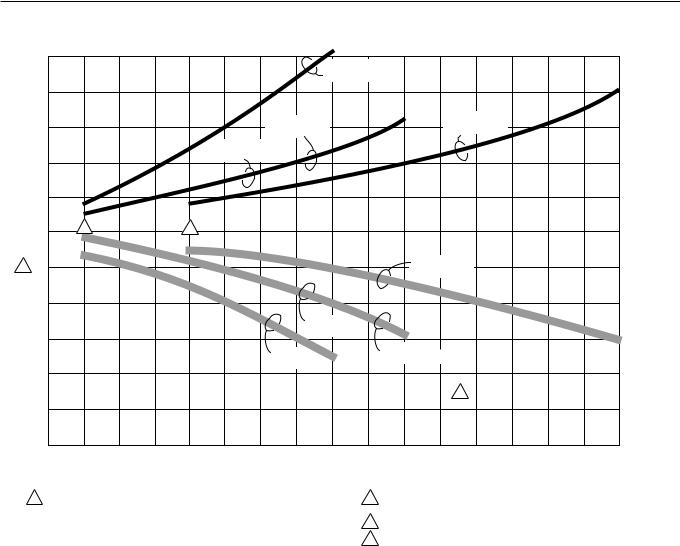
Capacity, Efficiency, Pressure Drop:
See Fig. 1, for capacity, pressure drop and ASHRAE dust spot efficiencies.
Fractional Efficiency:
70% efficient on 0.3 micron particles at 500 fpm.
90% efficient on 1.0 micron particles at 500 fpm.
99% efficient on 10.0 micron particles at 500 fpm.
Temperature Ratings:
Operating Ambient: 40° to 125° F (4° to 52° C). Temperature of Airflow Through Cells: 40° to 125° F
(4° to 52° C).
Maximum Cell Washing Temperature: 220° F (140° C). Storage and Shipping Ambient: Minus 40° F to plus 140° F
(minus 40° C to plus 60° C).
Mounting:
Mounts in the return air duct of a forced air heating, cooling, or ventilating system. Mount upstream from the atomizing humidifier. See the Planning the Installation section.
Table 1. Current Draw.
|
|
|
|
|
|
|
|
|
|
Max. Current (A) |
|
|
Size |
|
|
|
|
|
No. |
|
220/ |
||
in. |
|
mm |
Cells |
120V |
240V |
|
|
|
|
|
|
16 x 20 |
|
406 x 508 |
2 |
0.4 |
0.2 |
|
|
|
|
|
|
16 x 25 |
|
406 x 635 |
2 |
0.4 |
0.2 |
|
|
|
|
|
|
20 x 20 |
|
508 x 508 |
2 |
0.4 |
0.2 |
|
|
|
|
|
|
20 x 25 |
|
508 x 635 |
2 |
0.4 |
0.2 |
|
|
|
|
|
|
Table 2. Shipping and Installation Weight.
|
|
|
|
|
Weight |
|
|
|
|
|
|
|
|
|
|
|
|
|
|
|
16 x 20 in. |
16 x 25 in. |
|
20 x 20 in. |
20 x 25 in. |
||||
|
(406 x 508 mm) |
(406 x 635 mm) |
|
(508 x 508 mm) |
(508 x 635 mm) |
||||
|
|
|
|
|
|
|
|
|
|
|
lb |
kg |
lb |
kg |
|
lb |
kg |
lb |
kg |
|
|
|
|
|
|
|
|
|
|
Electronic Cell (Each) |
5 |
2.25 |
6 |
2.7 |
|
6-3/16 |
2.8 |
7-1/2 |
3.4 |
|
|
|
|
|
|
|
|
|
|
Shipping Weight |
30 |
13.6 |
33 |
15.0 |
|
33 |
15.0 |
38 |
17.2 |
|
|
|
|
|
|
|
|
|
|
Installed Weight |
26 |
11.6 |
28 |
12.7 |
|
29 |
13.2 |
33 |
15.0 |
(Cells Included) |
|
|
|
|
|
|
|
|
|
|
|
|
|
|
|
|
|
|
|
ORDERING INFORMATION
When purchasing replacement and modernization products from your TRADELINE® wholesaler or distributor, refer to the TRADELINE® Catalog or price sheets for complete ordering number, or specify
1.Order number.
2.Voltage and frequency.
3.Dimensions: 16 x 20, 16 x 25, 20 x 20, or 20 x 25 in. (406 x 508, 406 x 635, 508 x 508, or 508 x 635 mm).
4.Conversion kit for changing two cell 120V, 60 Hz models to 240V, 60 Hz or 220/240V, 50 Hz.
5.W8600F Air Cleaner Monitor, if desired.
6.W8600A AIRWATCH™ Indicator, if desired.
If you have additional questions, need further information, or would like to comment on our products or services, please write or phone:
1.Home and Building Control Customer Assistance Honeywell, 1885 Douglas Drive North
Golden Valley, MN 55422-4386 (612) 951-1000
2.Visit our web site @ www.honeywell.com/yourhome/
In Canada—Honeywell Limited/Honeywell Limitée, 155 Gordon Baker Road, North York, Ontario M2H 3N7.
International Sales and Service Offices in all principal cities of the world. Manufacturing in Australia, Canada, Finland, France, Germany, Japan, Mexico, Netherlands, Spain, Taiwan, United Kingdom, U.S.A.
68-0240-1 |
2 |
F300E ELECTRONIC AIR CLEANER
AIR CLEANER EFFICIENCY AND PRESSURE DROP AT VARIOUS AIRFLOW RATES.
|
|
|
|
|
|
|
|
|
|
|
|
|
|
|
|
|
.25 |
|
|
|
|
|
|
|
|
|
|
16 x 20 in. |
|
|
|
|
|
|
[62.2] |
|
|
|
|
|
|
|
|
|
|
|
|
|
|
|
|
|
|
|
||
|
|
|
|
|
|
|
|
|
[406 x 508 mm] |
|
|
|
|
|
|
|
[Pa] |
|
|
|
|
|
|
|
|
|
|
|
|
|
|
|
|
|
|
.20 |
|
|
|
|
|
|
|
|
|
|
|
|
|
|
|
|
|
|
[49.7] |
in. wc |
|
|
|
|
|
|
|
16 x 25 in. |
|
|
|
20 x 25 in. |
|
|
|
|
|||
|
|
|
|
|
|
|
|
|
|
|
|
|
.15 |
IN |
||||
|
|
|
|
|
|
|
|
|
|
[508 x 635 mm] |
|
|
||||||
|
|
|
|
|
|
|
[406 x 635 mm] |
|
|
|
|
|||||||
|
|
|
|
|
|
|
|
|
|
|
|
|
|
[37.3] |
DROP |
|||
|
|
|
|
|
|
|
|
|
|
|
|
|
|
|
|
|
||
|
|
|
|
|
|
20 x 20 in. |
|
|
|
|
|
|
|
|
|
|
||
|
|
|
|
|
|
[508 x 508 mm] |
|
|
|
|
|
|
|
|
|
|||
|
|
|
|
|
|
|
|
|
|
|
|
|
|
10 |
PRESSURE |
|||
|
|
|
|
|
|
|
|
|
|
|
|
|
|
|
|
|
||
|
|
|
|
|
|
|
|
|
|
|
|
|
|
|
|
|
[24.9] |
|
|
|
|
|
|
|
|
|
|
|
|
|
|
|
|
|
|
.05 |
|
|
|
|
|
|
|
|
|
|
|
|
|
|
|
|
|
|
[12.4] |
|
|
100 |
2 |
|
|
3 |
|
|
|
|
|
|
|
|
|
|
|
0 |
|
1 |
90 |
|
|
|
|
|
|
|
|
|
20 x 25 in. |
|
|
|
|
|
|
|
|
|
|
|
|
|
|
|
|
(508 x 635 mm) |
|
|
|
|
|
||||
PERCENT |
|
|
|
|
|
|
|
|
|
|
|
|
|
|
|
|||
80 |
|
|
|
|
|
|
|
|
|
|
|
|
|
|
|
|
|
|
|
|
|
|
|
|
|
|
|
|
|
|
|
|
|
|
|
|
|
EFFICIENCY, |
|
|
|
|
|
|
|
20 x 20 in. |
|
|
|
|
|
|
|
|
|
|
|
|
|
|
|
|
|
(508 x 508 mm) |
|
|
|
|
|
|
|
|
|||
70 |
|
|
|
|
|
|
|
|
|
|
|
|
|
|
|
|
|
|
|
|
|
|
|
|
|
16 x 20 in. |
|
|
16 x 25 in. |
|
|
|
|
|
|
|
|
|
|
|
|
|
|
|
|
|
(406 x 635 mm) |
|
|
|
|
|
|
|||
|
|
|
|
|
|
|
(406 x 508 mm) |
|
|
|
|
|
|
|
||||
|
|
|
|
|
|
|
|
|
|
|
|
|
|
|
|
|||
SPOT |
60 |
|
|
|
|
|
|
|
|
|
|
|
|
|
|
|
|
|
|
|
|
|
|
|
|
|
|
|
|
|
4 |
|
|
|
|
|
|
DUST |
|
|
|
|
|
|
|
|
|
|
|
|
|
|
|
|
|
|
50 |
|
|
|
|
|
|
|
|
|
|
|
|
|
|
|
|
|
|
|
400 |
500 |
600 |
700 |
800 |
900 |
1000 |
1100 |
1200 |
1300 |
1400 |
1500 |
1600 |
1700 |
1800 |
1900 |
2000 |
|
|
[680] |
[850] |
[1020] |
[1190] |
[1360] |
[1530] |
[1700] |
[1870] |
[2040] |
[2210] |
[2380] |
[2550] |
[2720] |
[2890] |
[3060] |
[3230] |
[3400] |
|
CAPACITY IN cfm [m3 /hr]
1 EFFICIENCY RATINGS BASED ON NATIONAL BUREAU OF |
2 |
MINIMUM RECOMMENDED cfm FOR 16 x 25 in. [406 x 635 mm], |
|
STANDARDS INITIAL DUST SPOT METHOD USING ATMOSPHERIC |
|
20 x 20 in. [508 x508 mm], 16 x 20 in. [406 x508 mm] MODELS. |
|
DUST, AND AMERICAN SOCIETY OF HEATING, REFRIGERATING |
3 |
MINIMUM RECOMMENDED cfm FOR 20 x 25 in. [508 x 635 mm] MODEL. |
|
AND AIR-CONDITIONING ENGINEERS STANDARDS 52.1-92. |
|||
|
|
||
|
4 |
SELECT SIZE THAT MOST CLOSELY FITS DIMENSIONS OF |
|
|
|
FURNACE/AIR HANDLER RETURN AIR OPENING |
|
|
|
M14730 |
Fig. 1. Air cleaner efficiency and pressure drop at various airflow rates.
Weight: |
Accessories: |
See Table 2. |
203365A Conversion Kit for changing 120V, 60 Hz power |
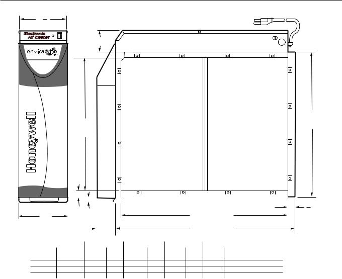
Dimensions: |
supply to 240V, 60 Hz or 220/240, 50 Hz. |
W8600F Air Cleaner Monitor. |
|
See Fig. 2. |
W8600A AIRWATCH™ Indicator. |
Underwriters Laboratories Inc. Listed: |
Repair Parts: |
File No. E30954. |
See Replacement Parts/Exploded View section. |
3 |
68-0240-1 |
F300E ELECTRONIC AIR CLEANER
6 38 (162)
SYSTEM
DIM. E
(SEE TABLE)
DIM. A (SEE TABLE)
|
|
|
|
|
|
|
|
|
|
|
|
|
|
|
|
|
|
|
|
|
|
|
|
|
|
|
|
|
|
|
|
|
|
|
|
|
|
|
|
|
|
|
|
|
|
|
|
|
|
6 |
3 |
|
|
|
|
|
5 |
|
|
|
|
|
|
|
|
|
DIM. C (SEE TABLE) |
|
|
|
|
|||
|
|
|
|
|
|
|
|
|
|
|
|
|
|
|
|
|
||||||||
|
|
|
|
8 |
|
|
|
|
|
|
|
|
|
|
|
|
|
|||||||
4 |
|
|
|
|
|
|
|
|
|
|
|
|
|
|
|
|
|
|||||||
|
|
|
|
|
|
|
|
|
|
|
|
|
|
|
|
|
|
|
|
|||||
(172) |
|
|
|
(16) |
|
|
|
|
|
|
|
|
|
|
|
|
|
|
|
|||||
|
|
|
|
|
|
|
|
|
|
|
|
|
|
|
|
|
|
|
|
|
|
|||
|
|
|
|
|
|
|
|
|
2-1/2 |
|
|
|
|
|
|
DIM. D (SEE TABLE) |
|
|
|
|
||||
|
|
|
|
|
|
|
|
|
(63) |
|
|
|
|
|
|
|
|
|
|
|
|
|
||
|
|
|
|
|
|
|
|
|
|
|
|
|
|
|
|
|
|
|
|
|
|
|
|
|
|
F300 |
|
|
|
|
|
|
|
|
DIM. A |
|
|
|
DIM. B |
|
DIM. C |
|
|
DIM. D |
DIM. E |
|
|
||
IN. |
|
|
MM |
|
|
|
IN. |
MM |
IN. |
MM |
IN. |
MM |
IN. |
MM |
IN. |
|
MM |
|
||||||
16 X 25 |
406 X 635 |
14 7/16 |
367 |
16 3/16 |
411 |
23 1/4 |
591 |
25 |
626 |
2 3/4 |
|
70 |
|
|||||||||||
16 X 20 |
406 X 508 |
14 7/16 |
367 |
16 3/16 |
411 |
18 1/4 |
457 |
20 |
509 |
2 3/4 |
|
70 |
|
|||||||||||
20 X 25 |
508 X 635 |
18 7/16 |
468 |
20 3/16 |
513 |
23 1/4 |
591 |
25 |
626 |
2 3/4 |
|
70 |
|
|||||||||||
20 X 20 |
508 X 508 |
18 7/16 |
468 |
20 3/16 |
513 |
18 1/4 |
457 |
20 |
509 |
2 3/4 |
|
70 |
|
|||||||||||
DIM. B
(SEE TABLE)
7
8
(22)
M14731
Fig. 2. Installation dimensions of Electronic Air Cleaner in in. (mm).
PLANNING THE INSTALLATION
Application
The F300E Electronic Air Cleaner is used in a forced air heating, cooling, or ventilating system. It removes airborne particles from the air circulated through it. All models have an internal air flow switch that operates the air cleaner when the system blower is on.
For most efficient air cleaning, airflow must be spread evenly across the face of the air cleaner. If the duct is a different size than the air cleaner cabinet, gradual transitions are recommended. If the duct turns sharply just before the air cleaner, turning vanes are recommended.
Applications with Air Conditioning
The air cleaner should be installed upstream from the evaporator coil. The air cleaner will help keep the coil clean, reducing maintenance.
Review Installation Requirements
The air cleaner should be installed where all the air passing through the system circulates through it. The best location is in the return air duct next to the blower compartment so the air cleaner can help keep the blower motor and evaporator coils clean.
IMPORTANT
Do not mount in the discharge air duct.
Applications with a Humidifier
An evaporative humidifier can be mounted upstream from the air cleaner. An atomizing humidifier should be mounted downstream from the air cleaner, even though hard water salts will be blown into the living space and deposited as dust. If an atomizing humidifier must be mounted upstream from the air cleaner:
68-0240-1 |
4 |

F300E ELECTRONIC AIR CLEANER
1.Mount it as far as possible upstream from the air cleaner.
2.Install a standard disposable furnace filter between the humidifier and the air cleaner to trap water droplets and hard water salts.
3.Frequently clean the air cleaner to prevent a hard water salt buildup.
NOTE: |
The volume of water that passes through an |
|
atomizing humidifier can overload the air |
|
cleaner, resulting in hard water salts being |
|
deposited as dust in the living space. |
Applications with an Activated Carbon Filter
An activated carbon (charcoal) filter can be used to remove odors or other gaseous contaminants (not particle-based) that are not removed by the air cleaner. Locate the carbon filter:
•Downstream from the air cleaner. This means that dust from the carbon filter will not be collected by the air cleaner and will be deposited in the living space.
•Outside the air cleaner cabinet. Some carbon filters are combustible and contact with high voltage could result in smoke or fire.
•Where carbon granules cannot fall into the electronic cell. If necessary, use a disposable furnace filter between the carbon filter and the electronic cell.
•With proper transitions, if the activated carbon filter requires a differently sized duct than the air cleaner. Allow 20 degrees expansion per side, per fitting.
NOTE: |
Honeywell does not offer carbon filters. Refer to |
|
an activated carbon filter manufacturer for sizing |
|
and application. |
Applications with Outdoor Air Intake
Return air temperature must be at least 40° F (4° C). Lower temperatures can cause ionizer wire failure. If outdoor air is used, warm it upstream from the air cleaner by:
•Making sure the outdoor intake is far enough upstream from the air cleaner so the return and outdoor air is thoroughly mixed. Stratified air can dump a stream of very cold air into one section of the air cleaner.
•Adding baffles upstream from the air cleaner to force thorough air mixing.
•Installing a Honeywell Home Ventilation System that transfers up to 80 percent of the heat from the exhaust air
to the incoming outside air. This keeps the incoming air above 40° F (4° C) and reduces energy usage.
•Installing a preheater if large amounts of outdoor air are used. The preheater, which could be an electric strip heater or hot water coil, should be controlled by a thermostat. Hot water or steam coils should be protected by a freeze-up control.
Optional W8600F Air Cleaner Monitor
The terminal board is recessed slightly so it or the wires will not interfere with installation. The entire power supply box can be unplugged and removed to provide access to the terminals. The W8600F Air Cleaner Monitor can be mounted in the living area or in the furnace room. It should be located in a convenient location to observe the display.
Optional W8600A AIRWATCH™ Indicator
The W8600A can be mounted next to the thermostat or in any other location in the living area of the home where the display can be conveniently observed. No wiring is necessary.
Choose Location
Choose a location that is readily accessible for regular inspection and cleaning. Allow at least 13 in. (330 mm) in front of the access door for removing the prefilter and electronic cell. Allow enough room above the power supply so it can be serviced without removing pipes, ducts, or other heating system components.
The air cleaner must be installed where the temperature will not exceed 40° to 125° F (4° to 52° C).
Choose Mounting Position
 WARNING
Heavy Equipment.
Can cause injury or equipment damage.
Do not mount the air cleaner with the access door facing down. If the access door faces down, the latch may not hold, and the cell and prefilter can fall unexpectedly. Also, nothing holds the cell and prefilter in place when the access door is opened.
The air cleaner can be mounted in any position except with the access door facing down. Following is a list of air cleaner mounting positions for a variety of furnace installations.
NOTE: |
At least 13 in. (330 mm) clearance is required |
|
between the access door and any obstructions |
|
for cell and prefilter maintenance. |
—Upflow “Highboy” furnace: Side installation; air cleaner is mounted vertically where return enters side inlet of furnace. See Fig. 3A.
—Upflow “Highboy” furnace: Installation beneath furnace (air cleaner cabinet can easily support weight of furnace and air conditioner coil). Air cleaner is mounted horizontally where return enters from below. See Fig. 3B.
—Upflow “Highboy” furnace: Closet installation. Air cleaner is mounted vertically on furnace between furnace and louvered return air opening in closet door. See Fig. 3C.
—“Lowboy” furnace: Air cleaner is mounted horizontally in return plenum just above furnace, opposite of supply plenum. See Fig. 3D.
—Downflow “Counterflow” furnace: Air cleaner is mounted horizontally in return duct or plenum just above furnace. See Fig. 3E.
—High capacity system: Two or more air cleaners can be used together. See Fig. 3F.
—Horizontal furnace: Air cleaner is mounted vertically where return enters. See Fig. G.
5 |
68-0240-1 |

F300E ELECTRONIC AIR CLEANER
A
B
D
C
E
F G
M14732A
Fig. 3. Mounting positions with variety of furnace installations.
Determine Duct Design Requirements
The air cleaner is adaptable to all new or existing forced air heating, cooling and ventilating systems used in residential applications. Transitions, turning vanes, or offsets may be needed in some applications for effective operation.
Transitions
Transitions are needed when the duct is a different size than the air cleaner cabinet. Gradual transitions reduce air turbulence and increase efficiency. Limit expansion to no more than 20 degrees or about 4 in. per running foot (100 mm per 300 linear mm) on each side of a transition fitting. See Fig. 4.
CHANGE DUCT SIZE GRADUALLY TO MINIMIZE TURBULENCE.
20 DEGREE EXPANSION PER SIDE PER FITTING (4 in. PER LINEAR FOOT
[100 mm PER 300 LINEAR mm]).
RETURN
AIR DUCT
TRANSITION FITTING 
ELECTRONIC AIR CLEANER CABINET |
M5626A |
Fig. 4. Change duct size gradually to minimize turbulence.
Turning Vanes
If the air cleaner is installed close to an elbow or angle fitting, install turning vanes inside the angle to distribute airflow more evenly across the face of the cell. See Fig. 5.
Offsets
If the duct connection to the furnace in a side installation allows less than 7 in. (178 mm) for mounting the air cleaner cabinet, add an offset to the elbow. See Fig. 5.
TYPICAL USE OF DUCT OFFSET TO ALLOW
SPACE FOR ELECTRONIC AIR CLEANER.
OFFSET
LESS
THAN 7 in.
(178 mm)
AT LEAST 1 7 in.
(178 mm)
1 TURNING VANES HELP DISTRIBUTE AIRFLOW EVENLY.
M14733
Fig. 5. Typical use of duct offset to allow space for electronic air cleaner.
68-0240-1 |
6 |
F300E ELECTRONIC AIR CLEANER
INSTALLATION
When Installing this Product…
1.Read these instructions carefully. Failure to follow them could damage the product or cause a hazardous condition.
2.Check the ratings given in the instructions and on the product to make sure the product is suitable for your application.
3.Installer must be a trained, experienced service technician.
4.After installation is complete, check out product operation as provided in these instructions.
 WARNING
Electric Shock Hazard.
Can cause electrical shock or equipment damage.
Do not connect to power before installation is complete.
Unpack Electronic Air Cleaner
Check that all components are included. The electronic air cleaner is shipped assembled. The unit consists of a galvanized steel cabinet, power supply with on-off switch and neon light, two electronic cells and prefilters, access door, and product data literature.
Order W8600F (optional), mounting hardware and installation literature separately.
Order W8600A (optional), including mounting hardware, batteries, and literature separately.
Clean Blower Compartment
Remove and discard the existing furnace filter.
Thoroughly clean the blower compartment.
If possible, power vacuum the ductwork to remove accumulated dust in an existing home, or construction dirt in a new home. The electronic air cleaner cannot remove dust that has settled in the blower compartment and distribution ducts.
Check the edges of the furnace fan blades for dirt buildup and clean as necessary. The fan will not deliver the rated cfm if the blades are dirty.
Fasten Cabinet To Furnace
NOTE: |
This procedure shows a side installation on a |
|
typical highboy furnace. You may need to alter |
|
the procedure to fit your application. |
Remove and set aside the access door, electronic cell(s) and prefilter(s).
Align the cabinet with the return air opening.
Create opening in furnace to match air cleaner cabinet opening.
Install a transition when the furnace and air cleaner openings are different sizes. See Fig. 4.
Place blocks under the cabinet so the unit is firmly supported and level. The 5/8 in. (16 mm) mounting foot on the cabinet hinge plate provides the minimum clearance required for the access door hinge.
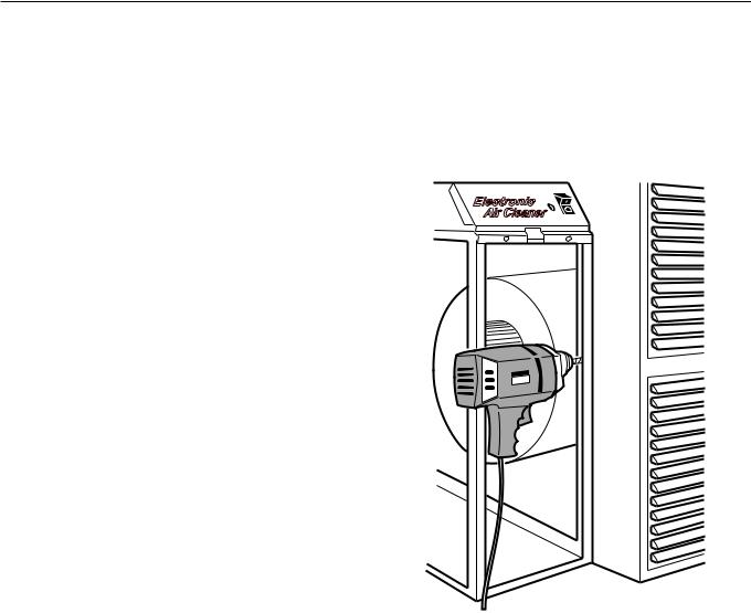
Attach the cabinet securely to the furnace. The unit can be attached directly, as shown, or a starting collar can first be fitted in the furnace opening. Either drill holes and fasten with sheet metal screws or rivets, or use slip joints. See Fig. 6.
M14734
Fig. 6. Fasten cabinet to furnace.
Install Turning Vanes
Mount turning vanes inside the elbow or angle fitting that is directly against the air cleaner cabinet. See Fig. 5 and 7.
Fasten Cabinet To Ductwork
Install a transition when the opening in the air cleaner cabinet and the duct are different sizes. See Fig. 4.
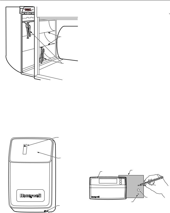
Fasten the other side of the cabinet to the elbow using sheet metal screws, rivets, or slip joints as appropriate. If drilling holes, use locking pliers to help hold the unit in place during drilling. See Fig. 7.
7 |
68-0240-1 |
F300E ELECTRONIC AIR CLEANER
SYSTEM
TURNING
VANES
LOCKING
PLIERS
M14735
Fig. 7. Connect ductwork to air cleaner. Note turning vanes. Locking pliers hold duct to air cleaner cabinet during installation.
Install Optional W8600F Air Cleaner Monitor
The W8600F Air Cleaner Monitor is an option available for use with the F300E.
The W8600F function indicator panel has four liquid crystal display (LCD) arrowheads that point to ON, BATTERY, SERVICE or FAULT. See Fig. 8. The arrowheads darken to indicate the existing EAC condition. See Table 3.
LCD
ON
BATTERY
SERVICE |
|
FAULT |
|
Air Cleaner Monitor |
FUNCTION |
INDICATOR |
|
|
PANEL |
RESET BUTTON
M11965
Fig. 8. W8600F Air Cleaner Monitor features.
|
Table 3. Description of W8600F |
||
|
|
|
Function Indicator Panel. |
|
|
|
|
|
|
|
|
Indicators |
|
|
Condition |
|
|
|
|
ON |
|
EAC is powered and system blower is |
|
|
|
running. |
|
|
|
|
|
BATTERY |
|
Battery that maintains W8600F memory is |
|
|
|
low and needs to be replaced. |
|
|
|
|
|
SERVICE |
|
EAC prefilter and cells need to be washed . |
|
|
|
|
|
FAULT |
|
• Shorting of collector plates. |
|
|
|
• Continuous ionizer or collector plate |
|
|
|
|
arcing. |
|
|
• |
Power supply failure. |
|
|
• |
Excessive current. |
|
|
• Major reduction in high voltage. |
|
|
|
• EAC prefilter and cells are past |
|
|
|
|
SERVICE level of dirt and need to be |
|
|
|
washed immediately. |
|
|
Call a service technician. |
|
|
|
|
|
W8600F Location
The styling of the W8600F is designed to blend with the latest T8600 family of Honeywell Chronotherm® IV Deluxe Programmable Thermostats. A special mounting template is included for mounting next to the T8600. The W8600F can also be mounted at any other convenient location in the living area or equipment room.
NOTE: |
The W8600F shares no electrical connections |
|
with the thermostat. |
Mounting
The following mounting instructions assume that the W8600F is mounted next to a T8600 Thermostat. If installing the monitor at another location, modify the procedure to fit the installation.
1.Hold the mounting template (included in the bag assembly) next to the T8600 as shown in Fig. 9.
2.Mark the holes for the screw anchors and the 3-conductor thermostat cable.
3.Remove the template and drill the holes.
4.Remove the W8600F from the base.
5.Position the W8600F base over the holes and install the anchors and screws. Tighten the screws until the base is mounted firmly on the wall.
THERMOSTAT
MOUNTING
WALLPLATE
TEMPLATE
WIRING HOLE
M11971
MOUNTING HOLES (2)
Fig. 9. Positioning mounting template.
68-0240-1 |
8 |
 Loading...