


DC 1010

HONEYWELL
DC 1010 / 1020
1030 / 1040
DIGITAL CONTROLLER
PRODUCT MANUAL
51-52-25-113
06/02

Before using this manual, please check to ensure the Model number, input type
Range and output match your requirements.
1. Front Panel Overview
1.1 Display
PV :Process Value, 4-digit display (Color Red)
SP :Set Point, 4-digit display (Color Green)
1.2 LED Indicators
OUT1 :Output 1, color green
OUT2 :Output 2, color green
AT :Auto-Tuning, color yellow
PRO :Program, color yellow
AL1 :Alarm 1, color red
AL2 :Alarm 2, color red
MAN :Manual, color yellow
1.3 Keys
SET :MODE & SET key
:SHIFT key
:DOWN key
:UP key
A/M :Auto/Manual key
2.2. Auto Tuning
2.1 When AT is set to ‘YES’, auto tuning can be initiated.
2.2 After completion of auto tuning, the PID parameter are automatically
Entered into memory.
2.3 ATVL = auto tuning offset, the off set value when entered will be calculated
and subtracted from the SP.
(It prevents over-shooting during auto tuning)
SP-ATVL = Auto-tuning value, ATVL = Auto tuning offset
Ex.) SP = 200°C, ATVL = 5, Auto tuning point is at 195°C
* ATVL means auto-tuning point (195°C) in the above example.
2.4 Auto tuning failure
2.4.1 ATVL is too large.
à If unsure, set ATVL = 0)
2.4.2 Process lag is to long for Auto Tune to function correctly.
à Set PID parameter manually.
DC1010/1020/1030/1040 PRODUCT MANUAL
2
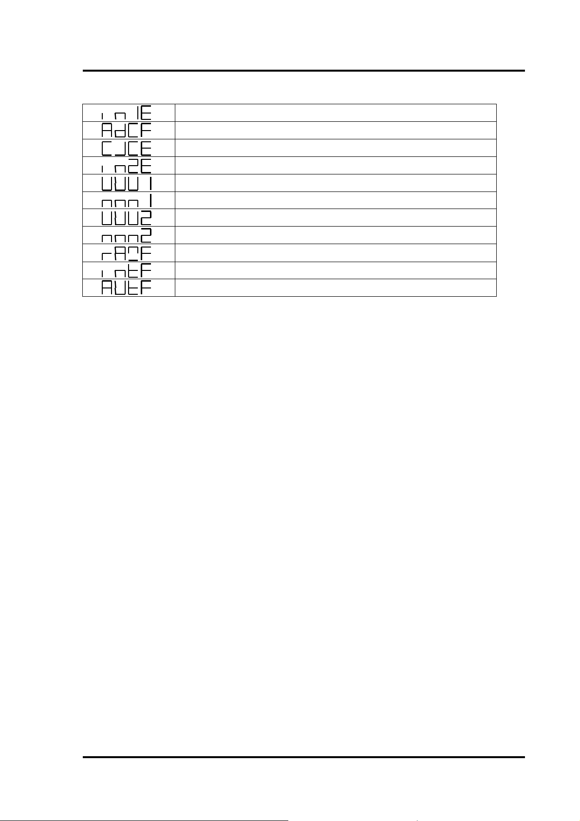
3.3. Error Information
Open circuit sensor input 1
* A/D converter failed
* Cold junction compensation failed
Open circuit of sensor input 2
PV exceeds USPL
PV under LSPL
Input 2 signal has exceeded the upper limit
Input 2 signal has exceeded the lower limit
* RAM failed
Interface failed
Auto tuning failed
Note) Error * code indicates critical failure unit must be replaced.
3
DC1010/1020/1030/1040 PRODUCT MANUAL
SET
SET
SET
SET
SET
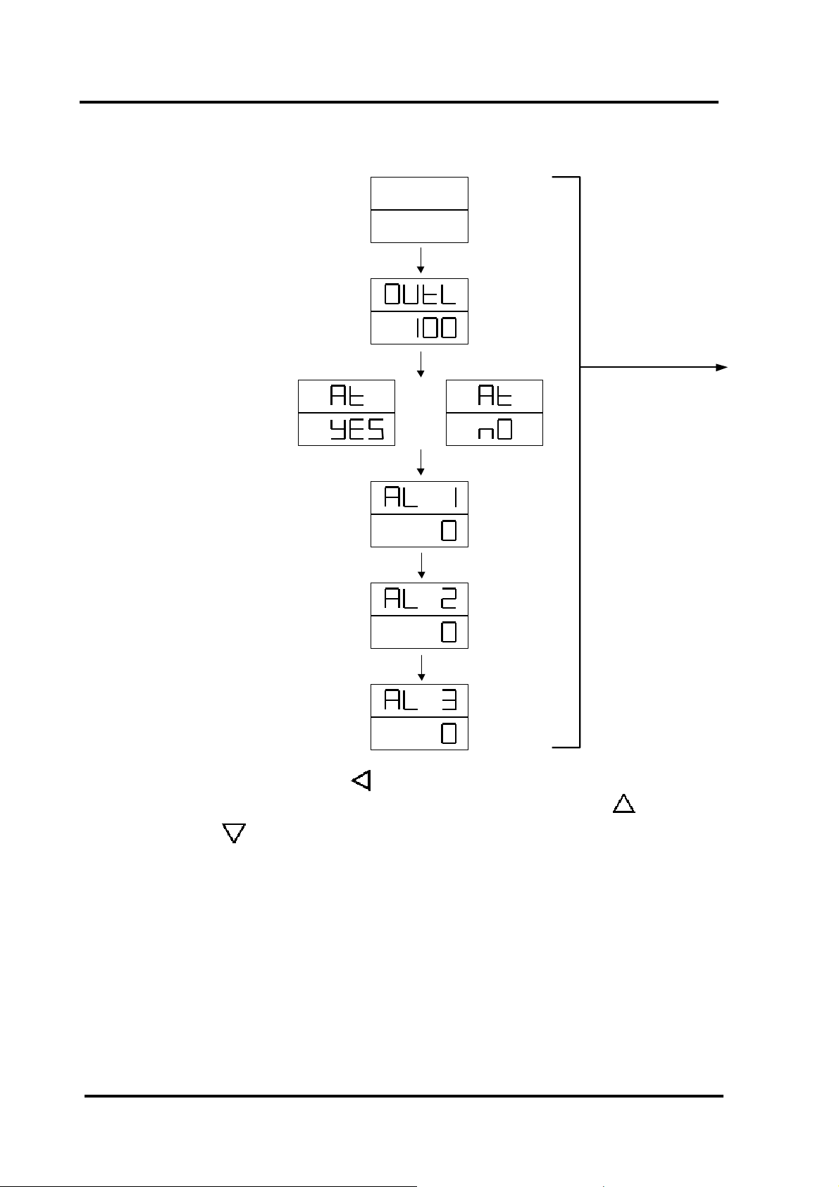
4.4. Operating Flow
Display PV
Display SP
Output
Percentage
Auto Tuning
Status
Alarm 1 Set
Alarm 2 Set
Alarm 3 Set
4.1 Level 1
PV
SP
Press SET key
for 5 sec
4.1.1 Press the SHIFT key ( ) to change the parameters, when the SHIFT key
is pressed, the first digit will start to blink. Press UP key ( ) or DOWN
key ( ) to increase or decrease the value of the digit, then press SHIFT
key again to go to the next digit, repeat the above procedure until the
required has been selected. Press the SET key to enter the desired value.
4.1.2 The SET key also has the function of changing MODEs. If SET key is
pressed, the display shows the next MODE.
4.1.3 Press SET key for 5 sec. The display goes to level 2, press the SET key
again to return to level 1.
4.1.4 If any key is not pressed for 1 minute the display will return to level 1.
4.1.5 If the A/M key is pressed the controller will switch to level 1.
4.1.6 If the output percentage is “0”, the controller output is off.
4
DC1010/1020/1030/1040 PRODUCT MANUAL
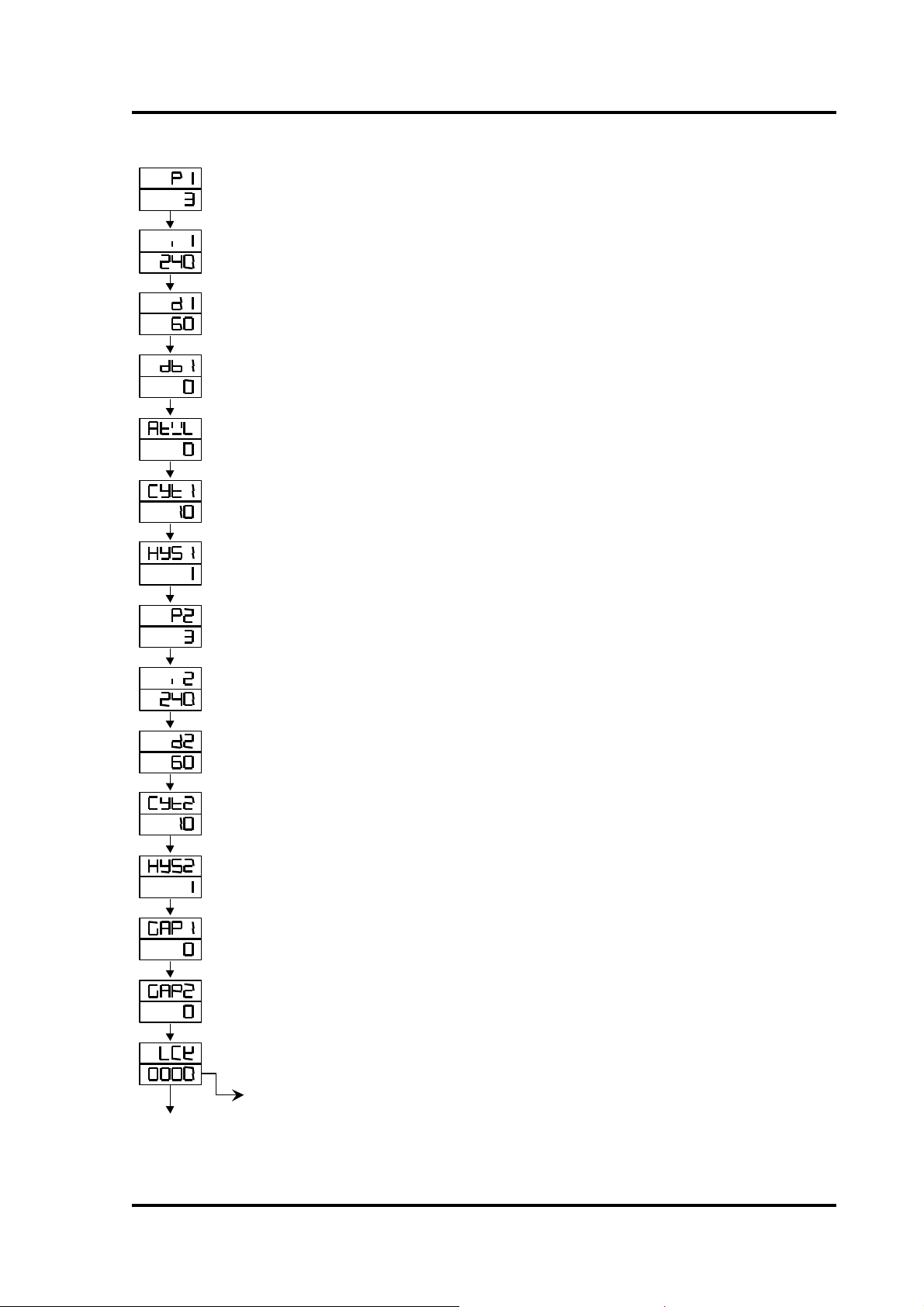
4.2 Level 2
Main Control
Proportional Band
Main Control
Integral Time
Main Control
Derivative Time
Main Control
Dead-band Time
Main Control
Auto Tuning off-set
Main Control
Proportional Cycle
Main Control
Hysterisis
Sub Control
Proportional band
Sub Control
Integral Time
Sub Control
Derivative Time
Sub Control
Proportional Cycle
Sub Control
Hysterisis
Main Control
Gap (Output 1)
Sub Control
Gap (Output 2)
Function Lock
Range: 0~200%
ON/OFF at P=0
Range: 0~3600 sec
Integral off at I=0
Range: 0~900 sec
Derivative off at D=0
Dead Time Compensation
Range: 0~1000 sec
Range: 0~USPL
Output (SSR à 1, 4~20mAà0, relayàover 10)
Range: 0~150 sec * Refer to 8.10 Cycle Time
For ON/OFF control only
Range: 0~1000
Same as P1
Same as I1
Same as D1
Same as CYT1
Same as HYS1
For output 2 use only, set the value turning
“OFF” early to SP
For output 2 use only, set the value turning
“ON” early to SP
LCK=0100, To enter Level 1 & 2 and to change their parameters allowed.
LCK=0110, To enter Level 1 & 2 and to change the parameters on Level 1 allowed.
LCK=0001, To enter Level 1 only and to change SP allowed.
LCK=0101, Nothing allowed except to change LCK.
SET
SET
SET
SET
SET
SET
SET
SET
SET
SET
SET
SET
SET
SET
SET
Return to
‘P1’
5
DC1010/1020/1030/1040 PRODUCT MANUAL
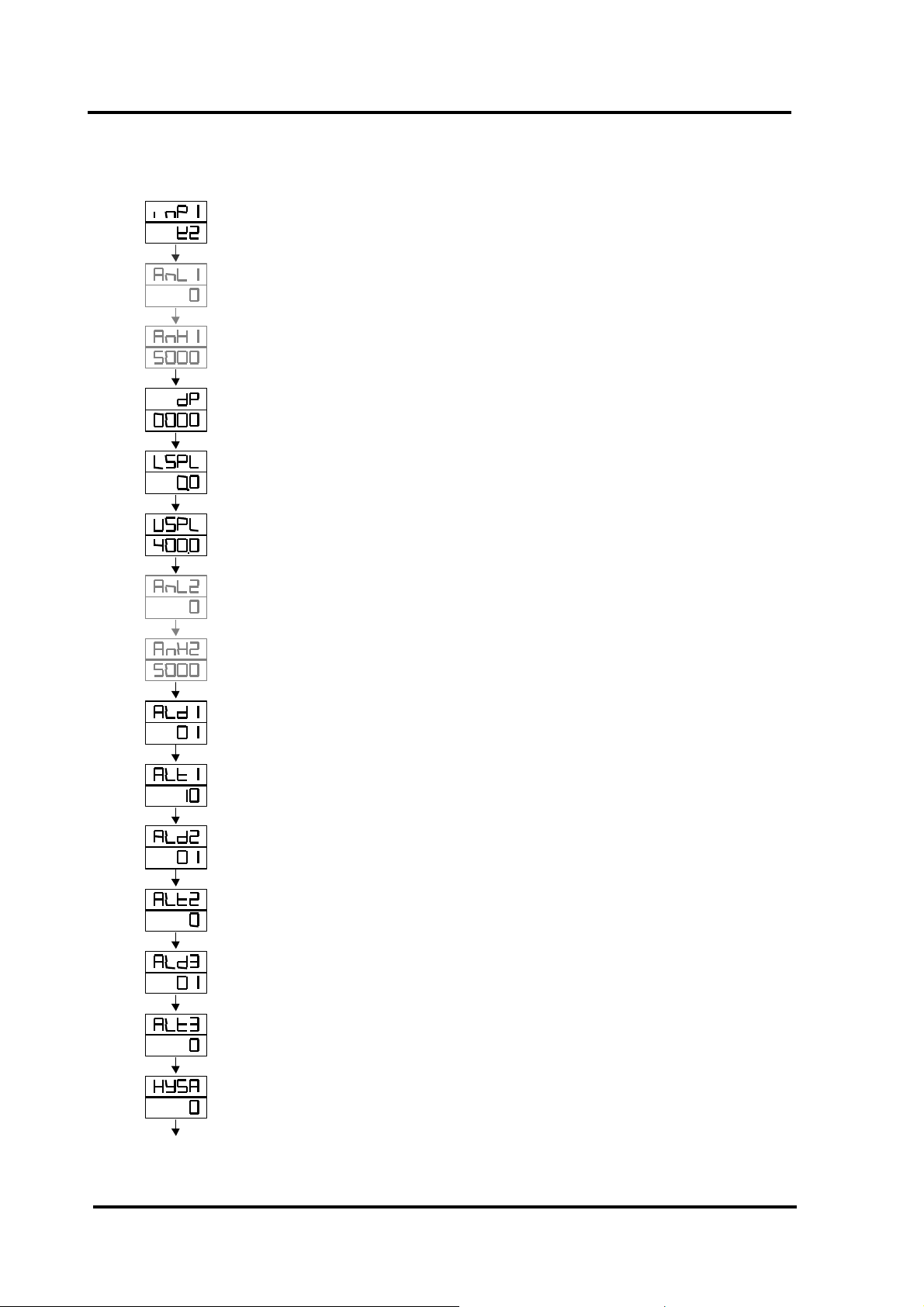
4.3 Level 3
Main Control
Input Selection
Main Control
Analog Zero set
Main Control
Analog Span set
Decimal point
Lower Set-point limit
Upper Set-point limit
Sub Control
Analog Zero set
Sub Control
Analog Span set
Alarm mode of AL1
Time set of Alarm 1
Alarm mode of AL2
Time set of Alarm 2
Alarm mode of AL3
Time set of Alarm 3
Hysterisis of Alarm
Select the input range.
Refer to 5.1 Input selection on P.13~P.14
Used as input code which are AN1 to AN5
Range: LSPL~USPL
Same as ANL1
To set the position of decimal point
To set the lowest point within INP1
To set the highest point within INP1
Used as input code which are AN1 to AN5
Range: LSPL~USPL
Same as ANL2
Range: 00~19
Refer to ‘6.1 Alarm Function Selection’ on P.15
Used in program function (Range: 0~99.59 min.)
Range: 00~19
Same as ALT 1
Range: 00~19
Same as ALT 1
Range: 0~1000
SET
SET
SET
SET
SET
SET
SET
SET
SET
SET
SET
SET
SET
SET
SET
When LCK=0000, press the SET key and SHIFT key for 5 seconds to enter level 3.
0=switching, 99.59=continuous, others = on delay time
6
DC1010/1020/1030/1040 PRODUCT MANUAL
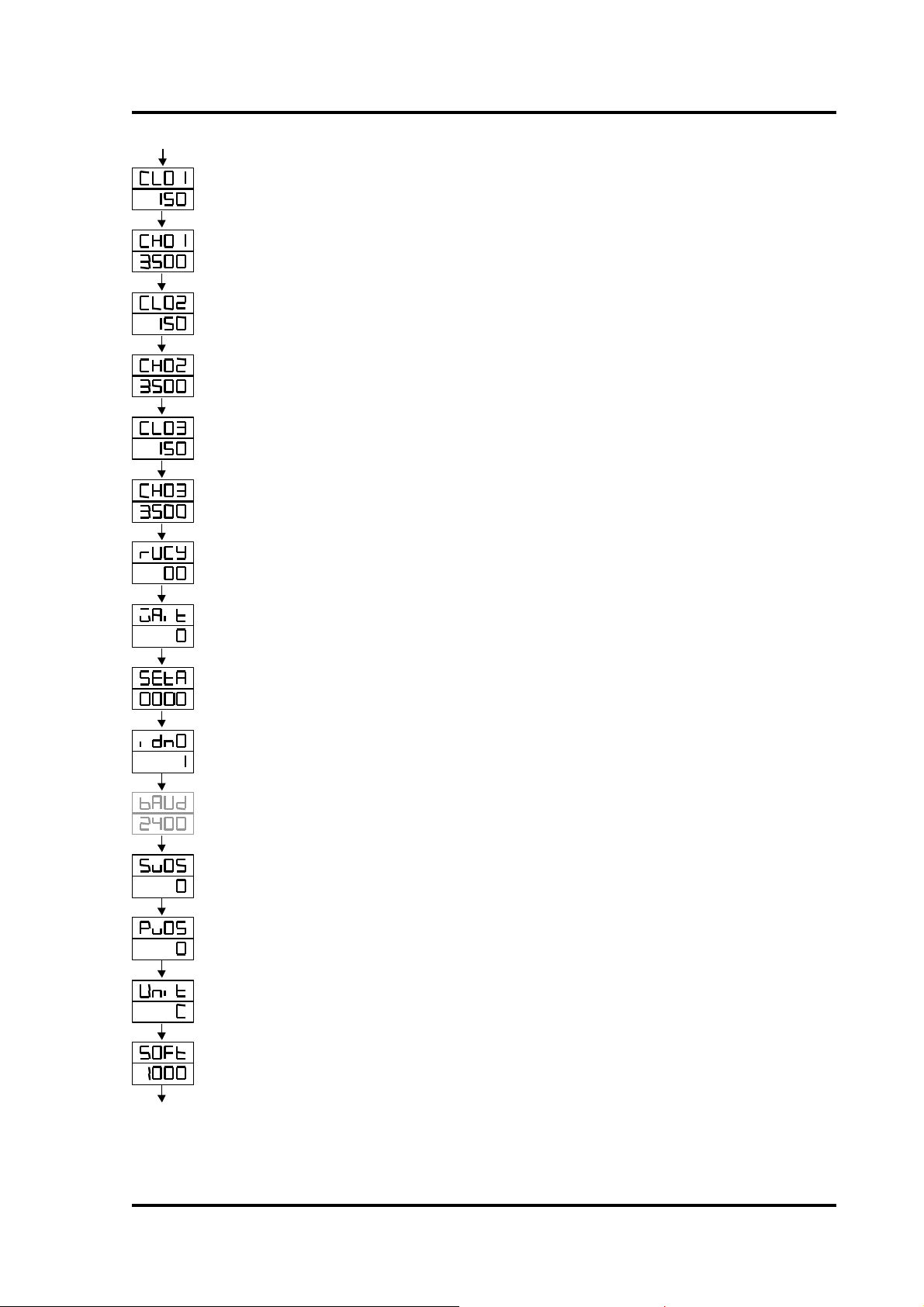
DC1010/1020/1030/1040 PRODUCT MANUAL
Main Control
Calibration
Main Control
Calibration high
Sub control
Calibration low
Sub Control
Calibration high
Transmitter control
Calibration low
Transmitter control
Calibration high
Timer for
Motor valve control
To use in program for
waiting continued operation
Relay Contact &
Program RUN & End ALM
ID number
(please skip this step)
Baud rate
(please skip this step)
Compensate SP
Compensate PV
Unit of PV & SP
Soft filter
(please skip this step)
To calibrate the low value of output
Range: LSPL~USPL (Current output only)
To calibrate the high value of output
Range: 0~9999 (Current output only)
Same as CL01
Same as CH01
Same as CL01
Same as CH01
Full run time of proportional motor (without potentiometer)
Range: 5~200 sec
0=No wait
Others = Wait time
0= “a” contact, 1= “b” contact
SET A.4=0 RUN alarm, SET A.4=1 END alarm
Communication ID number
UART band rate selection
Range: 110~9600 BIT/sec
Range: -1000~1000
Range: LSPL~USPL
Range: C, F, A (analog)
Adjust the response time of PV (the bigger, the faster)
Range: 0.05~1.00
SET
SET
SET
SET
SET
SET
SET
SET
SET
SET
SET
SET
SET
SET
SET
7
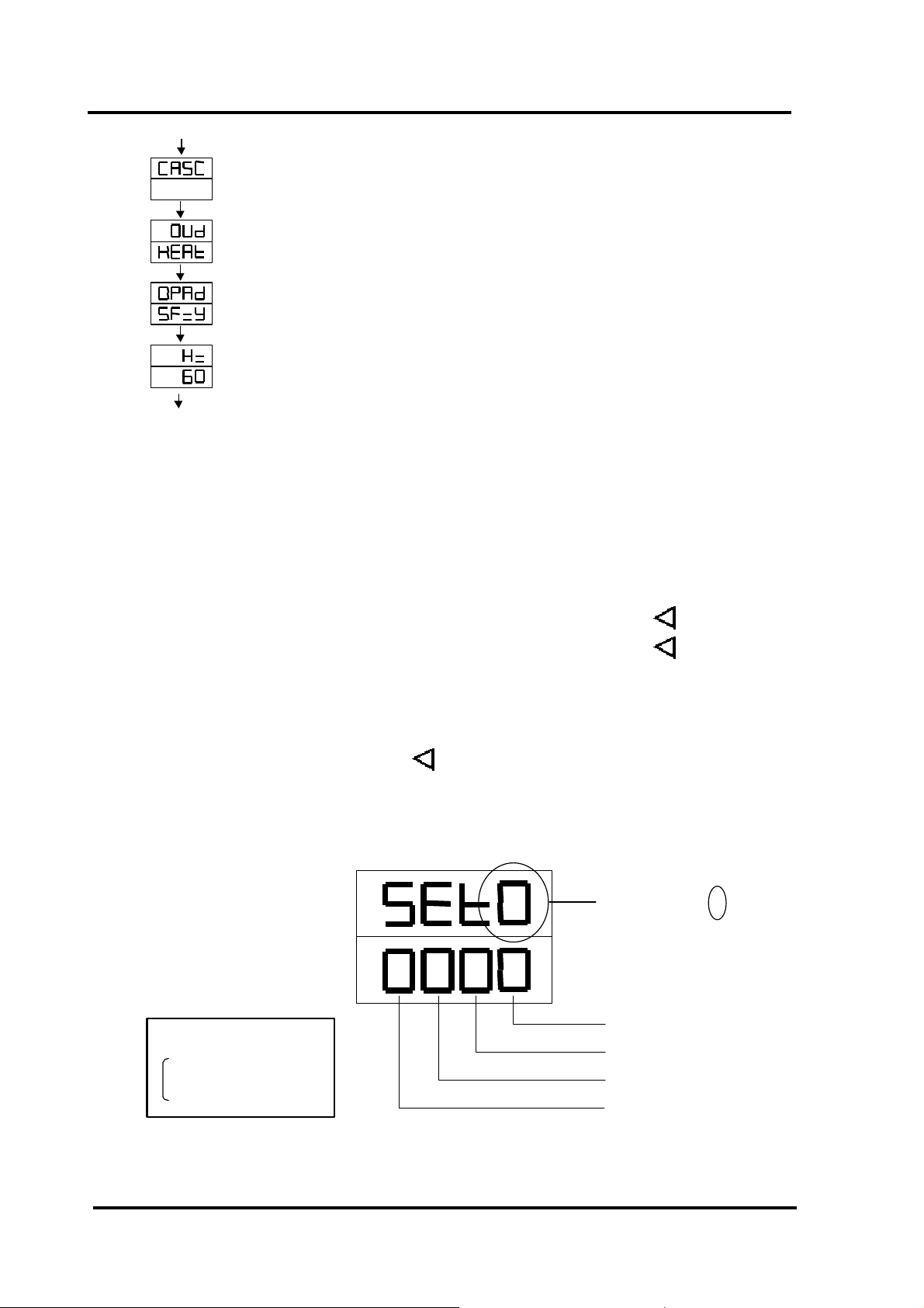
Return to ‘INP1’
Alternative: heat, cool
Alternative: PID, Fuzzy
Alternative: 50, 60Hz
PV
SP
0= lock (skip)
1= open (display)
Status definition
Please skip this step
Action mode
Control action
Frequency
* Check if the frequency is right. If not, change it, please.
SET
SET
SET
SET
4.4 Level 4 (LOCK FUNCTION)
4.4.1 Functions of LCK
LCK=0100, To enter Level 1 & 2 and to change their parameters allowed.
LCK=0110, To enter Level 1 & 2 and to change the parameters on Level 1 allowed.
LCK=0001, To enter Level 1 only and to change SP allowed.
LCK=0000, To enter Level 3 allowed then press SET + SHIFT key ( )
LCK=1111, To enter Level 4 allowed then press SET + SHIFT key ( )
LCK=0101, Nothing allowed except to change LCK.
4.4.2 Let the display go to “LCK” in level 2, and set “1111” in LCK, then press
SET key and SHIFT key ( ) for 5 seconds to enter “SET” status. There
are SET0.1 to SET9.4 for use.
DC1010/1020/1030/1040 PRODUCT MANUAL
SET No. (SET 0 . ∗)
Status of SET ∗.1
Status of SET ∗.2
Status of SET ∗.3
Status of SET ∗.4
8
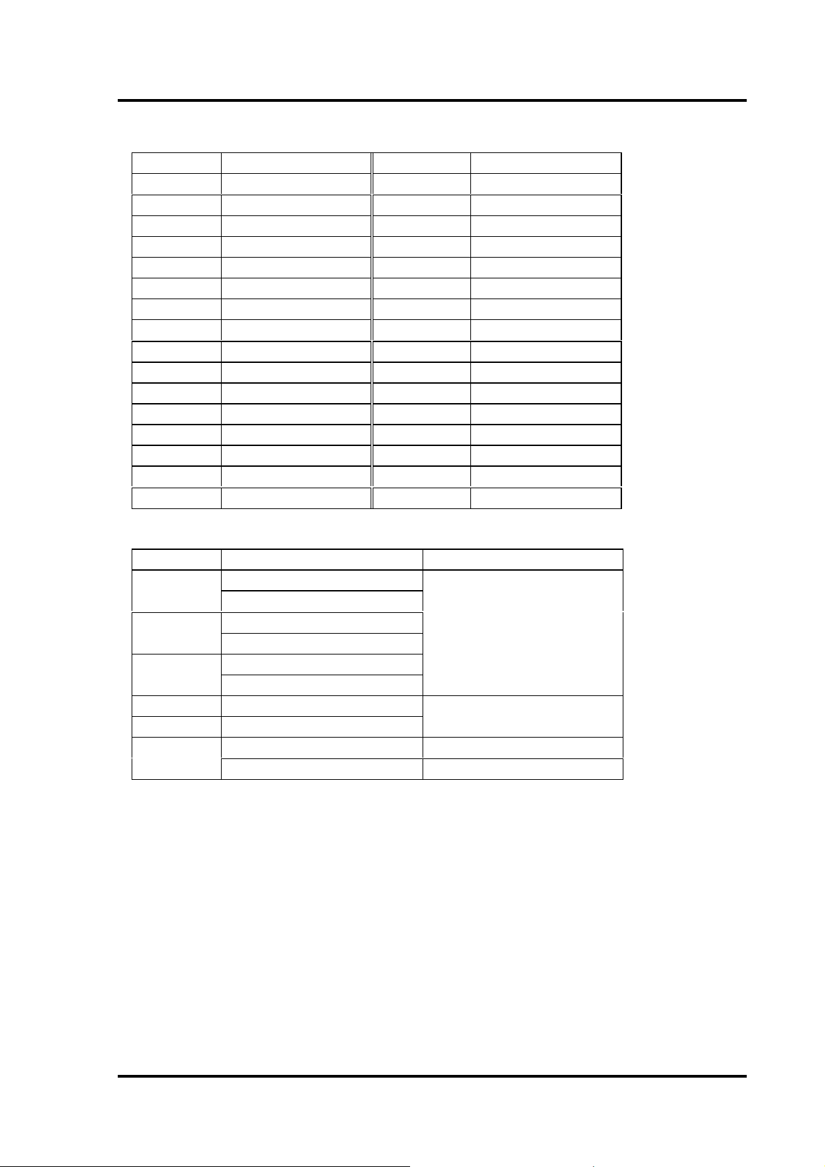
4.4.3 Functions of SETs
SET Function SET Function
1.1 OUTL 5.1 CL02, CH02
1.2 AT 5.2 CL03, CH03
1.3 AL1 5.3 Rucy, WAIT, HYSM
1.4 AL2 5.4 IDNO, BAUD
2.1 AL3 6.1 SVOS
2.2 ANL1, ANH1, DP 6.2 PVOS
2.3 LSPL, USPL 6.3 UNIT
2.4 ANL2, ANH2 6.4 SOFT
3.1 ALD1 7.1 CASC
3.2 ALT1 7.2 OUD
3.3 ALD2 7.3 OPAD
3.4 ALT2 7.4 Hz
4.1 ALD3
4.2 ALT3
4.3 HYSA
4.4 CL01, CH01
SET Function Remarks
8.1
8.2
8.3
9.3 TRS SP
9.4 TRS PV
0.3
* Caution: Please don’t operate SET8.4, otherwise the process of the controller will
be in confusion.
0= No Repeat
1= Program Repeat
0= No Power Failure
1= With Power Failure
0= Start from 0
1= Start from PV
0= No Remote SP
1= Remote SP
Program Use
Auxiliary Output Use
9
DC1010/1020/1030/1040 PRODUCT MANUAL
 Loading...