


CM921
WIRELESS PROGRAMMABLE THERMOSTAT
PRODUCT SPECIFICATION SHEET
The CM921 thermostat is designed to provide automatic time and temperature control of heating or cooling systems in villas and apartments.
It can be used as part of a system in conjunction with combiboilers, oil-burners and gas fired boilers, circulation pumps, thermal actuators, zone values and electric heating systems (<10A). In combination with other CM921 room units and HC60NG receivers it can be used to control multi-zone applications (up to 4 zones).
The radio frequency controlled CM921 system pack consists of a room unit CMT921A and a relay box R6660D (HC60NG). No wiring to the room unit is required. The installer only needs to wire the relay box to the controlled device (e.g. boiler) and mount the room unit in a suitable location where RF communication is reliable. The CM921 uses reliable RF communication technology in the 868MHz band.
The CM921 extra large LCD display, dynamic text display and controls layout are identical to the CM901 ‘wired’ thermostat. The unit is ideal for consumers who want reliable and precise temperature control from a modern looking, simple to program and easy-to-use product.
FEATURES
•CM921 can be installed without disrupting your room décor as no wiring connection is required between the room unit and the boiler
•Attractive, slim, ultra-modern styling makes it ideal for location in any type of home
•1-day heating programming
•A dynamic text display on the LCD that gives enhanced feedback to the user / installer
•LCD Backlighting to illuminate the display for easier viewing in low light conditions
•Reliable RF communication utilising 868 MHz band with 1 % duty cycle limit to minimise communication disturbance
•Every room unit can be bound with several relay boxes (e.g. to control several electric heating panels)
•Armchair programmed
• Holiday button that provides energy savings by reducing to a constant temperature for 1 to 99 days when people are on holiday, returning to normal operation (AUTO or MANUAL) on the day of their return.
•EEPROM memory holds the user program indefinitely
•OFF position has an integral frost protection setting at minimum 5°C (installer adjustable) so that pipes in the house will never freeze in winter.
•Communication compatibility with other Honeywell product such as HR80, HM80 and HCE80.
•CM921 can be used to control a zoning system with up to 4 zones
•Maximum system efficiency and extended boiler life due to unique zoning system synchronisation
•Automatic Summer / Winter time change adjusts the time automatically to daylight saving time.
•Standard room units and receiver boxes are used for zoning applications algorithm
•When used with the table top stand the room unit can be positioned anywhere in the room where RF communication is reliable
•24...230V 10A resistive, 3A inductive SPDT relay provides compatibility with most domestic central heating systems reducing the need to stock many different models.
•The HC60NG may be surface or wallbox mounted.
•Installer Set-Up Mode allows extra functions to be set at the discretion of the installer to match the consumer applications and needs:
•Optimisation
•Pump Exercise
•Upper / Lower Setpoint Limit Adjust
•Temperature offset
•Minimum ON time
•Cycle rate
•Heat / Cool Operation
•Proportional Band Width
•Fail-safe mode for communication loss
1 EN0H 8557 UK07 R0 09/06

CM921 CHRONOTHERM
CONTROLS/DISPLAY LAYOUT
Room Unit Layout:
1.Day & Date Display
2.Time Display
3.Dynamic Text Display (DTD)
4.Burner On Indicator
5.Battery Low Indicator
6.Temperature Display
7.Temperature Change Buttons
8.Information Enquiry Button
9.Slider Switch
10.Green OK Button
11.Program Buttons
12.Battery Cover
13.Battery Compartment
14.Holiday Button
15.Time Change Buttons
SPECIFICATIONS
ELECTRICAL
Room unit power : 2 x 1.5 V IEC LR6 (AA) Alkaline cells supply
Battery life |
: Minimum 2 years |
Battery |
: Program retained in EEPROM |
replacement |
|
Receiver power |
: 230V AC +10% - 15%, 50Hz |
supply |
|
Switch type |
: SPDT potential free |
Output rating |
: 24-230 V AC, 10 A resistive, 3 A inductive |
|
0.6 p.f. |
Wiring (receiver |
: Cable terminals for mains and relay wiring |
only) |
for max 2.5 mm2 wire |
Wire access |
: from the rear (wall box mounting), right |
|
and bottom |
RF
RF operation band : ISM (868.0-868.6) MHz, 1% duty cycle
RF communication : 30 m in a residential building environment range
RF communication : short, high rate transmissions to minimise technology air time and avoid collisions
Blocking immunity : Receiver class 2 (ETSI EN300 220-1 version 1.3.1)
RF binding method : Factory pre-bound with the room unit.
ENVIRONMENTAL & STANDARDS
: 0 to 40oC when relay load < 8 A
: 0 to 30oC when relay load > 8 A
Shipping & storage : -20 to 55oC temperature
Humidity |
: Humidity range 10 to 90% rh, non- |
|
|
|
condensing |
IP class |
: |
30 |
Meeting the |
: |
EN60730-1(Nov 2000), EN55014-1(1997), |
following |
|
EN55014-2(2000), ETSI EN300 220-3 |
standards |
|
(2000), ETSI EN301 489-3(2000) |
2
EN0H 8557 UK07 R0 09/06
TEMPERATURE CONTROL
Sensing element |
: |
100K (@ 25 oC ) NTC thermistor |
Control form |
: |
Fuzzy Logic Algorithm |
Minimum ON |
|
10% of cycle time (min one minute), |
time |
|
adjustable to 2 to 5 min (see installer set |
|
|
up) |
Cycle rate |
: |
Selectable by application (see installer |
|
|
set up) |
Temperature |
: |
+0.5 K (nominal) @ 20oC, 50% load 3K |
control accuracy |
|
/hour |
Fail-safe mode |
: |
Off or cycling depending on the CM927 |
|
|
system set-up |
TIME SETTING/PROGRAMMING
Time display |
: 24 hour or 12 hour AM/PM format |
|
Time keeping |
: |
Typically better than 10 minutes per year |
accuracy |
|
|
Program |
: 1-day with 6 daily time and temperature |
|
|
|
level changes |
Time setting |
: Time of day - 1 minute |
|
resolution |
|
Program – 10 minute steps |
Temperature |
: |
Program : 5 to 35oC in 0.5 oC steps Frost |
setting range |
|
: 5 oC or equal to lower limit (5 |
|
|
oC to 16 oC). Frost protection does not |
|
|
work in cooling mode |
Room |
: |
From 0 oC to 50 oC |
Temperature |
|
|
display range |
|
|
CM921 CHRONOTHERM
INSTALLER SET-UP
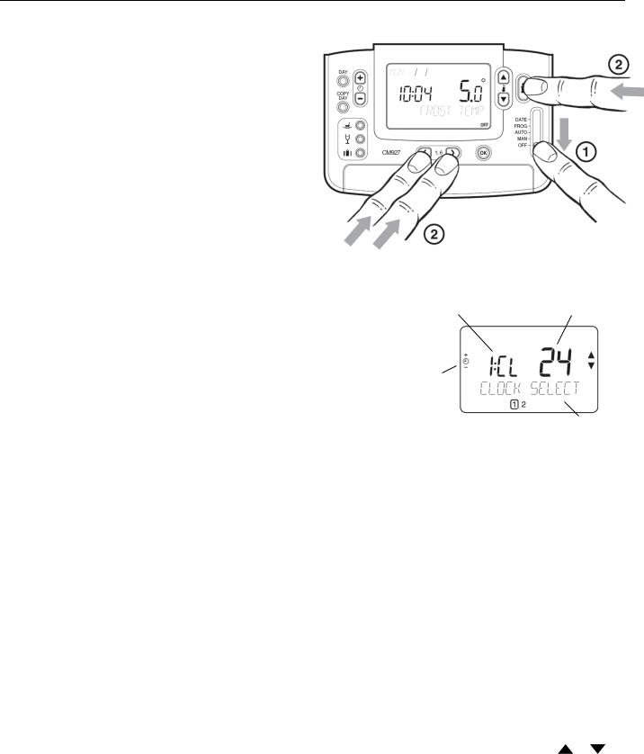
To enter the installer set-up mode:
a)Move the slider switch to the OFF position.
b)Press and hold the INFO i button and the two program buttons ‘< >’ together.
c)The unit will display the first parameter of installer parameter group category 1 (from n.1 to n.19).
d)Press the TEMP  or
or  buttons to change the factory setting. The display will flash indicating that a change has been made.
e)Press the green OK button to confirm this change and the display will stop flashing.
f)Press the  + button to go to the next parameter.
g)Press the program button > to go to category 2 in the Installer mode (from n.1 to n.14).
h)To exit the installer mode, move the slider switch to the AUTO or MAN positions.
In Installer set-up we can:
Set-up specific applications parameters
Enable special features
Configure system timing master for the zoning system
Abbreviated Set-Up Description
e.g. Cl = Clock Format
Installer Set-up Number
(Press  + or - to change) e.g. 1 = Clock Format
Factory Setting or New Choice
Press TEMP  or
or  to change e.g. 12 = AM/PM Format 24 = 24hr Format
Brief Description of the
Parameter Function.
Specific Applications |
Setting |
What do you need to change? |
|
|||
|
|
Cycle/ |
Minimum |
Note : All parameters listed below belong to category 2 – System |
||
|
|
Hour |
ON time |
Parameters (see Installer Parameters Table) |
|
|
|
|
|
(in minutes) |
|
|
|
Heating |
Gas Boilers |
6 |
1 |
No changes required |
|
|
|
(<30KW) |
|
|
|
|
|
|
|
|
|
|
|
|
|
Oil Boiler |
3 |
4 |
1. |
Set Minimum ON Time to 4 minutes. |
|
|
|
|
|
2. |
Set Cycle/Hour to 3. |
|
|
|
|
|
|
|
|
|
Thermal Actuator |
12 |
1 |
Set Cycle/Hour to 12. |
|
|
|
|
|
|
|
|
|
|
Zone valve |
6 |
1 |
No changes required. |
|
|
|
|
|
|
|
|
|
Air |
|
|
|
1. |
Configure the thermostat to allow switching between heating |
|
conditioning |
|
|
|
|
and cooling modes (set parameter n.4:HC to 1) |
|
|
|
|
|
2. |
Set the thermostat accordingly to the required mode of |
|
|
|
|
|
|
operation (heating or cooling) by pressing the TEMP |
or |
|
|
|
|
|
buttons together for 5 seconds. Modify the cooling program |
|
|
|
|
|
|
as required. |
|
|
Heat Pump/ |
3 |
4 |
1. |
Set Minimum ON Time to 4 minutes. |
|
|
Air conditioner |
|
|
2. |
Set Cycle/Hour to 3. |
|
|
|
|
|
|
|
|
|
Fan coil |
6 |
1 |
No changes required. |
|
|
|
|
|
|
|
|
|
3 EN0H 8557 UK07 R0 09/06
 Loading...