


T8602C
T8602C Chronotherm
Deluxe Programmable Thermostats
INSTALLATION INSTRUCTIONS
APPLICATION
The T8602 Chronotherm® IV Deluxe Programmable
Thermostat provides electronic control of 24 Vac singlestage heating and cooling systems. Refer to Table 1 for
Table 1. Description of T8602 Thermostats.
T8602 System Changeover
C Heat-Cool Manual Heat-Off-Cool On-Auto System and fan selections are done by
System
Selection
a general description of the thermostat. All T8602
thermostats are powered by batteries.
Fan
Selection Comments
keyboard.
®
IV
MERCURY NOTICE
If this control is replacing a control that contains
mercury in a sealed tube, do not place your old
control in the trash. Dispose of properly.
Contact your local waste management authority
for instructions regarding recycling and the
proper disposal of the old thermostat.
INSTALLATION
When Installing this Product...
1. Read these instructions carefully. Failure to follow
the instructions can damage the product or cause
a hazardous condition.
2. Check the ratings given in the instructions and on
the product to make sure the product is suitable
for your application.
3. Installer must be a trained, experienced service
technician.
4. After completing installation, use these instructions to check out the product operation.
Location
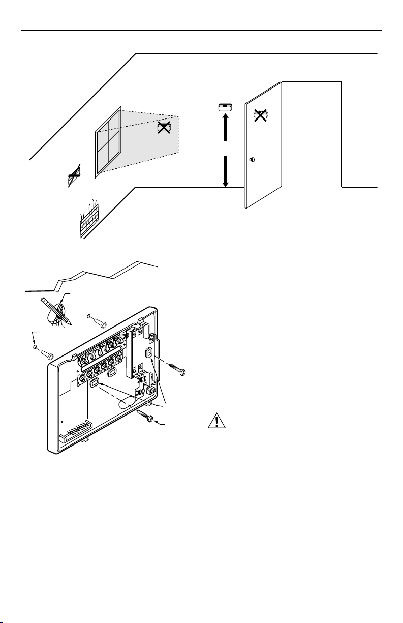
Install the thermostat about 1.5m (5 ft) above the floor in
an area with good air circulation at average temperature.
See Fig. 1.
Do not install the thermostat where it can be affected by:
— drafts, or dead spots behind doors and in corners.
— hot or cold air from ducts.
— radiant heat from sun or appliances.
— concealed pipes and chimneys.
— unheated (uncooled) areas such as an outside wall
behind the thermostat.
Wallplate Installation
The thermostat can be mounted horizontally on the wall
or on a 50.8 mm x 101.6 mm (2 in. x 4 in.) wiring box.
Position wallplate horizontally on the wall or on a
50.8 mm x 101.6 mm (2 in. x 4 in.) wiring box.
1. Position and level the wallplate (for appearance
only). The thermostat will function properly even
when not level.
®U.S. Registered Trademark
Copyright © 2001 Honeywell • • All Rights Reserved
69-1567
T8602C CHRONOTHERM® IV DELUXE PROGRAMMABLE THERMOSTATS
NO
WIRES
THROUGH WALL
WALL
ANCHORS
(2)
Fig. 2. Mounting the wallplate.
YES
NO
1.5 METERS
(5 FEET)
Fig. 1. Typical location of thermostat.
2. Use a pencil to mark the mounting holes. See Fig. 2.
WALL
3. Remove the wallplate from the wall and drill two
4.76 mm (3/16 inch) holes in the wall (if drywall)
as marked. For firmer material such as plaster,
drill two 5.56 mm (7/32 inch) holes. Gently tap
anchors (provided) into the drilled holes until flush
with the wall.
4. Position the wallplate over the holes, pulling wires
through the wiring opening.
5. Loosely insert the mounting screws into the holes.
6. Tighten mounting screws.
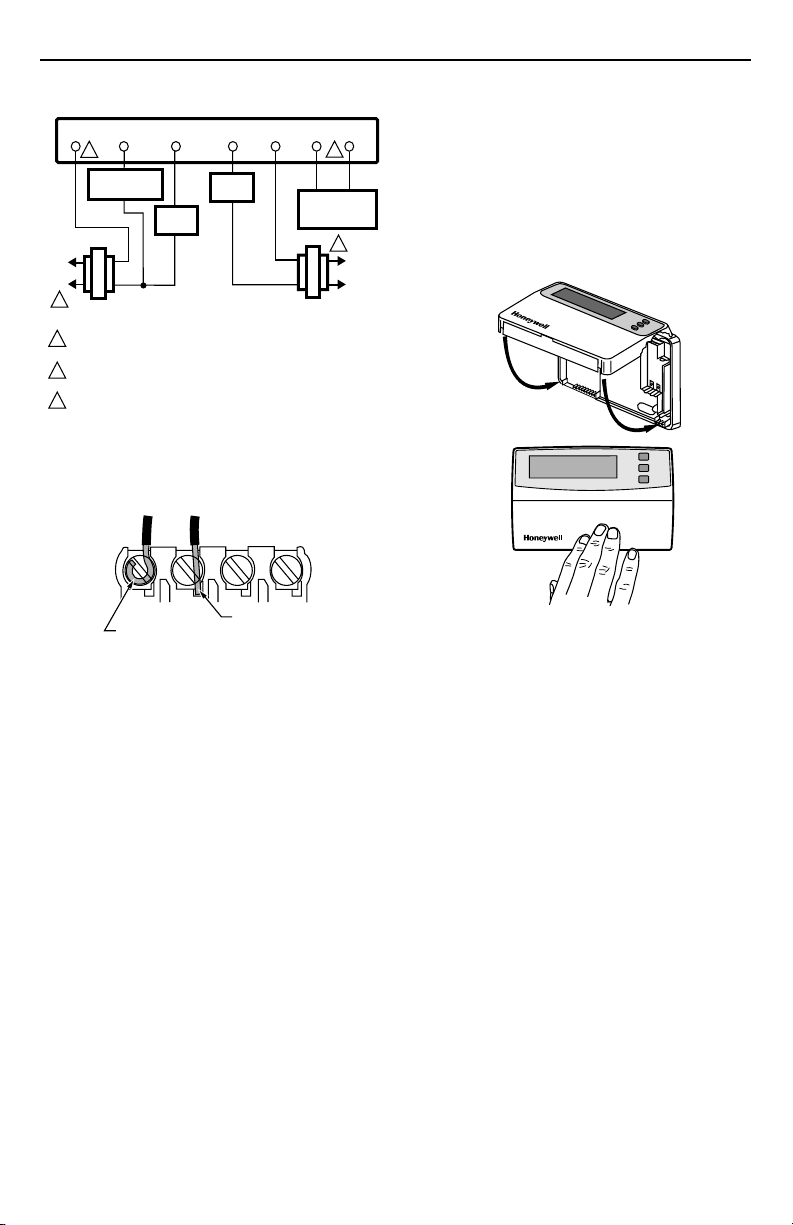
WIRING
All wiring must comply with local electrical codes and
ordinances. Refer to Fig. 3 for typical hookup. A letter
MOUNTING
HOLES
MOUNTING
SCREWS
M15044
code is located near each terminal for identification.
CAUTION
Disconnect power before wiring to prevent
electrical shock or equipment damage.
1. Loosen the terminal screws on the wallplate and
connect the system wires. See Fig. 4.
IMPORTANT
2. Securely tighten each terminal screw.
3. Push excess wire back into the hole.
4. Plug the hole with nonflammable insulation to
prevent drafts from affecting the thermostat.
NO
M10856
Use 18 gauge, color-coded thermostat cable
for proper wiring.
69-1567
2
T8602C CHRONOTHERM® IV DELUXE PROGRAMMABLE THERMOSTATS
THERMOSTAT
YG
RC
2
COMPRESSOR
CONTACTOR
FAN
RELAY
L1
(HOT)
L2
1
COOLING
TRANSFORMER
1
POWER SUPPLY. PROVIDE DISCONNECT MEANS AND OVERLOAD
PROTECTION AS REQUIRED.
JUMPER RC TERMINAL TO R TERMINAL WHEN INSTALLED ON A
2
ONE TRANSFORMER SYSTEM.
3
AVAILABLE ON SELECT MODELS. OT WIRES MUST HAVE A
SEPARATE CABLE FROM THE THERMOSTAT CABLE.
Fig. 3. Typical hookup in heat and cool
system with two transformers.
FOR WRAPAROUND
INSERTION STRIP
7/16 IN. (11 MM).
HEAT
RELAY
FOR STRAIGHT
INSERTION STRIP
5/16 IN. (8 MM).
RW
Fig. 4. Proper wiring technique.
OTOT
3
OUTDOOR
TEMPERATURE
SENSOR
1
HEATING
TRANSFORMER
M10855
M4826
Mounting Thermostat
1. Engage tabs at the top of the thermostat and
wallplate. See Fig. 5.
2. Press lower edge of case to close and latch.
NOTE: To remove the thermostat from the wall, first
pull out at the bottom of the thermostat;
remove top last.
L1
(HOT)
L2
A.
ENGAGE TABS
AT TOP OF
THERMOSTAT
AND WALLPLATE.
B.
PRESS LOWER
EDGE OF CASE
TO LATCH.
Fig. 5. Mounting thermostat on wallplate.
Using Thermostat Keys
The thermostat keys are used to:
• set current day and time,
• program times and setpoints for heating and cooling,
• temporarily override program temperatures,
• display present setting,
• configure Installer Setup,
• check Self-Test,
• display outdoor temperature (select models),
• set the system operation,
• set the fan operation.
M14628
3
69-1567
T8602C CHRONOTHERM® IV DELUXE PROGRAMMABLE THERMOSTATS
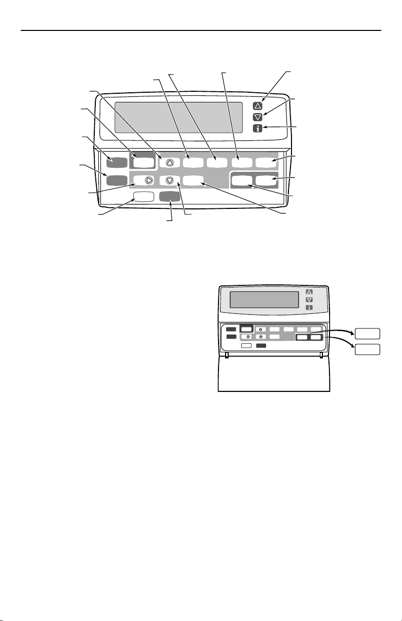
See Fig. 6 for the location of the keys.
INCREASE TIME SETTING
OR SCROLL FORWARD
THROUGH INSTALLER SETUP
AND SYSTEM TEST
SET CURRENT
DAY AND TIME
RETURN TO
NORMAL
OPERATIONS
ENTER
INDEFINITE
OR TIMED
HOLD MODE
SET CURRENT OR
PROGRAM DAY
CHANGE BETWEEN
DAYLIGHT SAVINGS
AND STANDARD TIME
SET WAKE TIMES
AND SETPOINTS
Set Current
Run
Day/Time
Program
Hold Temp
Day
Daylight
Time
COPY ONE PROGRAMMED
DAY TO ANOTHER DAY
SET LEAVE TIMES
AND SETPOINTS
Time Set Program
Wake
Heat/Cool
Settings
Copy
DECREASE TIME SETTING OR
SCROLL BACKWARD THROUGH
INSTALLER SETUP AND SYSTEM TEST
SET RETURN TIMES
AND SETPOINTS
Leave
Return Sleep
System Fan
Fig. 6. T8602C key locations and descriptions.
SETTINGS
System and Fan Settings
The system default setting is Heat and the fan default
setting is Auto. Use the System and Fan keys to change
the settings. See Fig. 7. The fan settings can be set for
each program period individually. The system selection
is for all the program periods.
System settings control the thermostat operation as
follows:
Heat: The thermostat controls the heating.
Off: Both the heating and cooling are off.
Cool: The thermostat controls the cooling.
Fan settings control the system fan as follows:
On: Fan operates continuously.
Auto: Fan operates with equipment.
Program
Hold Temp
Fig. 7. Thermostat System and Fan key locations.
NOTE: Always press the keys with your fingertip or
Time Set Program
Run
Set Current
Day/Time
Day
Daylight
Copy
Time
similar blunt tool. Sharp instruments like a pen
or pencil point can damage the keyboard.
INCREASE TEMPERATURE
SETTING OR SCROLL
FORWARD THROUGH
INSTALLER SETUP OPTIONS
DECREASE TEMPERATURE
SETTING OR SCROLL
BACKWARD THROUGH
INSTALLER SETUP OPTIONS
DISPLAY INFORMATION
SUCH AS PRESENT
SETTINGS AND OUTDOOR
TEMPERATURE
SET SLEEP TIMES
AND SETPOINTS
SELECT FAN
OPERATION
SELECT SYSTEM
OPERATION
CHANGE BETWEEN
HEATING AND COOLING
SETPOINTS
Leave
Wake
Return
Heat/Cool
System Fan
Settings
Sleep
M14625
M14624
System
Fan
69-1567
4
 Loading...