


 Loading...
T8600D, T8601D and T8602D
Chronotherm® IV Deluxe Programmable
Thermostats
APPLICATION
The T8600, T8601 and T8602 Chronotherm® IV Deluxe Programmable Thermostats provide electronic control of 24 Vac single-stage heating and cooling systems.
T8600/T8601/T8602
FEATURES AND BENEFITS
•Full seven-day program capability; different schedules and temperature setpoints may be selected for everyday to match the homeowner’s flexible schedule.
•Copy key makes programming easier and faster for the installer and homeowner.
•Daylight Savings Time (DST) key for quick change in and out of Daylight Savings Time.
•Models available with programmable fan operation for added homeowner comfort.
•Easy temporary temperature setpoint changes for current period, vacation hold (1 to 255 days) or indefinite hold adds to the homeowner comfort and energy savings.
•Frequently used keys are located by the Liquid Crystal Display (LCD) for quick and easy access to information.
•Attractive styling complements any decor to the homeowner’s delight.
•Back lighting the large display makes the LCD very easy to read.
PRODUCT DATA
•Models available with outdoor temperature sensor capability for homeowner convenience. The sensor is also more accurate than a thermometer.
•Configurable features allows one model to be used to replace many different models (less inventory, no longer need to carry separate models to get these features).
—°F or °C temperature display;
—Automatic or manual changeover;
—Electric or conventional heat fan operation
—Adjustable heating cycle rate.
•Minimum off time for cooling compressors and heat pumps protects the equipment and extends the equipment life.
•Easy installation, setup and system test saves installer time and increases productivity.
•Self-test simplifies troubleshooting and saves time by overriding the time delays.
•Adaptive Intelligent Recovery™ control brings the room temperature to temperature setpoint at the programmed time, maximizing comfort and energy savings.
•Setpoints are permanently held in memory (no batteries used) and retained during power outages for increased installer and homeowner convenience.
•Power stealing, hardwired and battery powered models available for virtually all equipment and application needs.
•Universal Versaguard™ Thermostat guards available for added security.
|
Contents |
Application ............................................................................. |
1 |
T8600/T8601/T8602 Features and Benefits ......................... |
1 |
Specifications ........................................................................ |
2 |
Ordering Information ............................................................. |
2 |
Installation ............................................................................. |
4 |
Wiring .................................................................................... |
4 |
Settings ................................................................................. |
6 |
Installer Setup ....................................................................... |
7 |
Installer Self-Test ................................................................. |
10 |
Thermostat Information ....................................................... |
11 |
Programming ....................................................................... |
11 |
Operation ............................................................................ |
16 |
Troubleshooting Guide ........................................................ |
17 |
Cross Reference ................................................................. |
19 |
Wiring Diagrams (Fig. 15-20) .............................................. |
24 |
® U.S. Registered Trademark |
|
68-0164-1 |
Copyright © 1997 Honeywell Inc. • |
• All Rights Reserved |

T8600D, T8601D AND T8602D CHRONOTHERM ® IV DELUXE PROGRAMMABLE THERMOSTATS
SPECIFICATIONS
IMPORTANT
The specifications given in this publication do not include normal manufacturing tolerances. Therefore, this unit might not exactly match the listed specifications. This product is tested and calibrated under closely controlled conditions, and some minor differences in performance can be expected if those conditions are changed.
Thermostat Models
T8600, T8601 and T8602 Thermostats provide features listed in Table 1.
Electrical Rating (Nominal Range):
24 Vac, 50/60 Hz.
20 to 30 Vac, 50/60 Hz.
Batteries:
Only T8602 models require batteries.
Loss of Power:
The thermostat will maintain programmed times and temperatures for the life of the product. The clock and day information is retained for a minimum of thirty minutes.
System Current Load Ratings:
6 VA maximum at 30 Vac, 50/60 Hz.
Output Relay Load Rating:
See Table 2.
Temperature:
Ratings:
Operating Ambient: 40°F to 110°F (4°C to 43°C).
Shipping: -30°F to +150°F (-34°C to +65°C).
Display Accuracy: ±1°F (±0.5°C).
Setpoint:
Range:
Heating: 40°F to 90°F (4.5°C to 32°C). Cooling: 45° F to 99°F (7°C to 35°C)
Differential: 3°F (1.5°C). Default Settings: see Table 3.
Minimum Stage Operation Time:
Minimum Off (Heat and Cool ): factory setting 5 minutes; option 0 to 5 minutes.
Humidity Ratings:
5% to 90% RH, noncondensing.
Clock Accuracy:
+1 minute per month.
Table 1. Thermostat Features.
|
|
|
|
|
|
|
|
|
|
|
|
System |
Fan |
|
|
|
|
System |
Changeover |
Selection |
Selection |
Comments |
|
|
|
|
|
|
|
|
|
T8600 |
(powered by either the heating or cooling system) |
|
|
||||
|
|
|
|
|
|
|
|
D |
|
Heat-Cool |
Automatic |
Heat-Off-Cool-Auto |
On-Auto |
System and fan selections are done by keyboard. |
|
|
|
|
|
|
|
|
|
T8601 |
(powered by common wire to supply power) |
|
|
|
|||
|
|
|
|
|
|
|
|
D |
|
Heat-Cool |
Automatic |
Heat-Off-Cool-Auto |
On-Auto |
System and fan selections are done by keyboard. |
|
|
|
|
|
|
|
|
|
T8602 |
(powered by batteries) |
|
|
|
|
||
|
|
|
|
|
|
|
|
D |
|
Heat-Cool |
Automatic |
Heat-Off-Cool-Auto |
On-Auto |
System and fan selections are done by keyboard. |
|
|
|
|
|
|
|
|
|
ORDERING INFORMATION
When purchasing replacement and modernization products from your TRADELINE® wholesaler or distributor, refer to the TRADELINE® Catalog or price sheets for complete ordering number.
If you have additional questions, need further information, or would like to comment on our products or services, please write or phone:
1.Your local Home and Building Control Sales Office (check white pages of your phone directory).
2.Home and Building Control Customer Logistics Honeywell Inc., 1885 Douglas Drive North Minneapolis, Minnesota 55422-4386
In Canada—Honeywell Limited/Honeywell Limitée, 35 Dynamic Drive, Scarborough, Ontario M1V 4Z9.
International Sales and Service Offices in all principal cities of the world. Manufacturing in Australia, Canada, Finland, France, Germany, Japan, Mexico, Netherlands, Spain, Taiwan, United Kingdom, U.S.A.
68-0164—1 |
2 |
T8600D, T8601D AND T8602D CHRONOTHERM ® IV DELUXE PROGRAMMABLE THERMOSTATS
Table 2. Maximum Amps at 30 Vac.
|
|
|
Relay |
Running (A) |
Inrush (A) |
|
|
|
Fan |
0.5 |
2.5 |
|
|
|
Heat |
1.5 |
3.5 |
|
|
|
Cool |
1.5 |
7.5 |
|
|
|
|
Table |
3. Default Setpoints. |
|
||
|
|
|
|
|
|
|
|
|
Heat |
Cool |
Fan |
Period |
Time |
|
Setpoint |
Setpoint |
Setting |
|
|
|
|
|
|
Wake |
6:00 AM |
|
70°F |
78°F |
Auto |
|
|
|
(21°C) |
(25.5°C) |
|
|
|
|
|
|
|
Leave |
8:00 AM |
|
62°F |
85°F |
Auto |
|
|
|
(16.5°C) |
(29.5°C) |
|
|
|
|
|
|
|
Return |
6:00 PM |
|
70°F |
78°F |
Auto |
|
|
|
(21°C) |
(25.5°C) |
|
|
|
|
|
|
|
Sleep |
10:00 PM |
|
62°F |
82°F |
Auto |
|
|
|
(16.5°C) |
(28°C) |
|
|
|
|
|
|
|
Finish:
Taupe color.
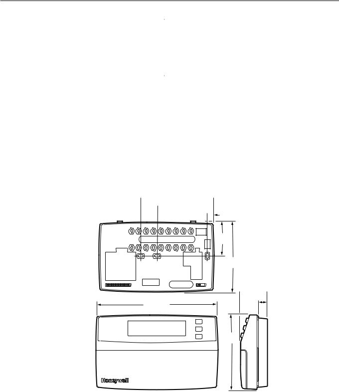
Dimensions:
See Fig. 1.
Mounting Means:
The thermostat mounts on a wallplate. The wallplate mounts horizontally on a wall or outlet box with two no. 6 x 32 screws (included).
Accessories:
C7089B Outdoor Temperature Sensors (69-1020). Universal Versaguard™ Thermostat guards.
 RECYCLING NOTICE
If this control is replacing a control that contains mercury in a sealed tube, do not place your old control in the trash.
Contact your local waste management authority for instructions regarding recycling and the proper disposal of the old thermostat.
 3-5/8 (92)
 2-3/4 (70)
3/8 (10) 
1-13/16
(46)
3-1/2
(89)
 1-9/16
  (40)
(40)
6-1/16 (154) |
1/2 |
|
|
|
(13) |
3-3/4
(95)
M10359
Fig. 1. Dimensions of thermostat in in. (mm).
3 |
68-0164—1 |
T8600D, T8601D AND T8602D CHRONOTHERM ® IV DELUXE PROGRAMMABLE THERMOSTATS
INSTALLATION
When Installing this Product...
1.Read these instructions carefully. Failure to follow the instructions can damage the product or cause a hazardous condition.
2.Check the ratings given in the instructions and on the product to make sure the product is suitable for your application.
3.Installer must be a trained, experienced service technician.
4.After completing installation, use these instructions to check out the product operation.
1.Position and level the wallplate (for appearance only). The thermostat will function properly even when not level.
2.Use a pencil to mark the mounting holes. See Fig. 3.
3.Remove the wallplate from the wall and drill two 3/16 inch holes in the wall (if drywall) as marked. For firmer material such as plaster, drill two 7/32 inch holes. Gently tap anchors (provided) into the drilled holes until flush with the wall.
4.Position the wallplate over the holes, pulling wires through the wiring opening.
5.Loosely insert the mounting screws into the holes.
6.Tighten mounting screws.
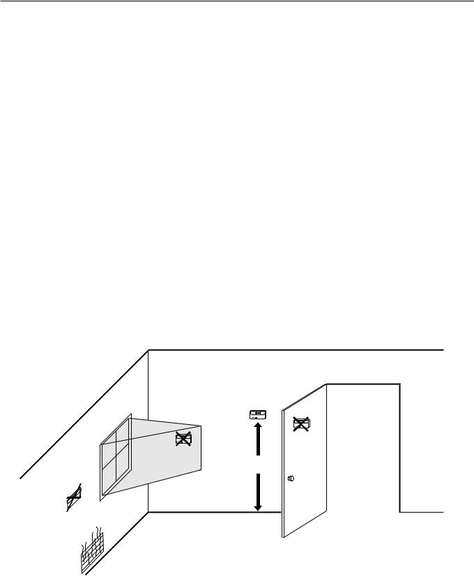
Location
Install the thermostat about 5 ft (1.5m) above the floor in an area with good air circulation at average temperature. See Fig. 2.
Do not install the thermostat where it can be affected by:
—drafts, or dead spots behind doors and in corners.
—hot or cold air from ducts.
—radiant heat from sun or appliances.
—concealed pipes and chimneys.
—unheated (uncooled) areas such as an outside wall behind the thermostat.
Wallplate Installation
The thermostat can be mounted horizontally on the wall or on a 2 in. x 4 in. wiring box. Position wallplate horizontally on the wall or on a 2 in. x 4 in. wiring box.
WIRING
All wiring must comply with local electrical codes and ordinances. Follow equipment manufacturer wiring instructions when available. Refer to Fig. 15 through 20 for typical hookups. A letter code is located near each terminal for identification. Refer to Table 4 for terminal designations.
 CAUTION
Disconnect power before wiring to prevent electrical shock or equipment damage.
1.Loosen the terminal screws on the wallplate and connect the system wires. See Fig. 4
YES
NO
NO
5 FEET
[1.5 METERS]
NO
M10106
Fig. 2. Typical location of thermostat.
68-0164—1 |
4 |
T8600D, T8601D AND T8602D CHRONOTHERM ® IV DELUXE PROGRAMMABLE THERMOSTATS
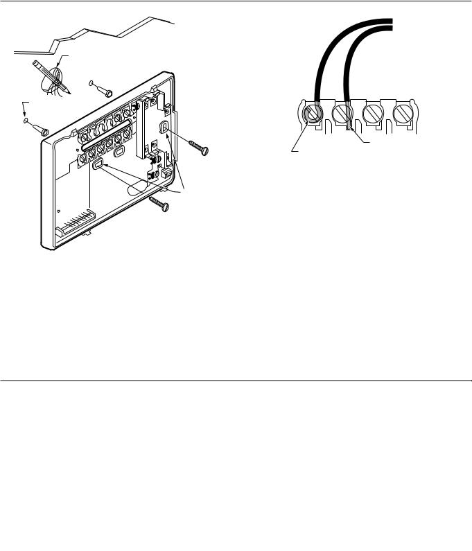
WALL
WIRES
THROUGH WALL
WALL ANCHORS
(2)
FOR WRAPAROUND INSERTION STRIP 7/16 IN. (11 MM).
FOR STRAIGHT INSERTION STRIP 5/16 IN. (8 MM).
M4826
Fig. 4. Proper wiring technique.
MOUNTING
HOLES
 MOUNTING
SCREWS
M15044
Fig. 3. Mounting the wallplate.
IMPORTANT
Use 18 gauge, color-coded thermostat cable for proper wiring.
2.Securely tighten each terminal screw.
3.Push excess wire back into the hole.
4.Plug the hole with nonflammable insulation to prevent drafts from affecting the thermostat.
Mounting Thermostat Wallplate
The thermostat mounts on the wallplate after they are installed.
1.Engage tabs at the top of thermostat and wallplate. See Fig. 5.
2.Press lower edge of case to latch.
NOTE: To remove the thermostat from the wall, first pull out at the bottom of the thermostat; then remove the top.
Table 4. Terminal Designations and Descriptions.
Standard |
Alternate |
|
|
|
Terminal |
Terminal |
|
|
|
Designations |
Designations |
Typical Connection |
Function |
Terminal Type |
|
|
|
|
|
B |
— |
Heating damper or changeover valve |
Output |
24V powered contact |
|
|
|
|
|
C |
Ba, C, X1, X2 |
Common |
Input |
|
G |
F |
Fan relay |
Output |
24V powered contact |
|
|
|
|
|
O |
R |
Cooling damper or changeover valve |
Output |
24V powered contact |
|
|
|
|
|
OT, OT |
— |
Outdoor temperature sensor (C7089B) |
Input |
— |
|
|
|
|
|
R |
V |
24V system or heating transformer |
Input |
— |
|
|
|
|
|
RC |
— |
24V cooling transformer |
Input |
— |
|
|
|
|
|
W |
H1, R3 |
Heating relay |
Output |
24V powered contact |
|
|
|
|
|
Y |
C1, M |
Compressor contactor |
Output |
24V powered contact |
|
|
|
|
|
a Some OEM models label the terminal for transformer common B.
5 |
68-0164—1 |

T8600D, T8601D AND T8602D CHRONOTHERM ® IV DELUXE PROGRAMMABLE THERMOSTATS
A. ENGAGE TABS AT TOP OF THERMOSTAT AND WALLPLATE.
B. PRESS LOWER EDGE OF CASE TO LATCH.
M15043
Fig. 5. Mounting thermostat on wallplate.
SETTINGS
Using Thermostat Keys
The thermostat keys are used to:
•set current day and time,
•program times and setpoints for heating and cooling,
•temporarily override program temperatures,
•display present setting,
•configure Installer Setup,
•check System Test,
•display outdoor temperature (select models),
•set the system operation,
•set the fan operation.
See Fig. 6 for the location of the keys.
System and Fan Settings
The system default setting is Heat and the fan default setting is Auto. Use the System and Fan keys to change the settings. See Fig. 7. The fan settings can be set for each program period individually. The system selection is for all the program periods.
SET WAKE TIMES
AND SETPOINTS
SET LEAVE TIMES
INCREASE TIME SETTING AND SETPOINTS
OR SCROLL FORWARD
THROUGH INSTALLER SETUP
AND SYSTEM TEST
SET RETURN TIMES
AND SETPOINTS
SET CURRENT
DAY AND TIME
RETURN TO
NORMAL
OPERATIONS
ENTER
INDEFINITE |
|
|
Time |
Set Program |
|
||
OR TIMED |
Run |
Set Current |
Wake |
Leave |
Return |
Sleep |
|
HOLD MODE |
Program |
Day/Time |
|||||
|
|
|
|
||||
|
Hold Temp |
Day |
Heat/Cool |
|
System |
Fan |
|
|
Settings |
|
|||||
|
|
|
|
|
|
||
SET CURRENT OR |
|
Daylight |
Copy |
|
|
|
|
|
Time |
|
|
|
|||
PROGRAM DAY |
|
|
|
|
|
||
|
|
|
|
|
|
||
CHANGE BETWEEN |
|
|
|
|
|
|
|
DAYLIGHT SAVINGS |
|
|
|
|
CHANGE BETWEEN |
||
AND STANDARD TIME |
|
|
|
|
HEATING AND COOLING |
||
|
|
|
|
|
SETPOINTS |
||
COPY ONE PROGRAMMED DAY TO ANOTHER DAY
DECREASE TIME SETTING
OR SCROLL BACKWARD THROUGH INSTALLER SETUP AND SYSTEM TEST
INCREASE TEMPERATURE SETTING OR SCROLL FORWARD THROUGH INSTALLER SETUP OPTIONS
DECREASE TEMPERATURE SETTING OR SCROLL BACKWARD THROUGH INSTALLER SETUP OPTIONS
DISPLAY INFORMATION SUCH AS PRESENT SETTINGS AND OUTDOOR TEMPERATURE
SET SLEEP
TIMES AND
SETPOINTS
SELECT FAN
OPERATION
SELECT SYSTEM
OPERATION
M10405A
Fig. 6. Key locations and descriptions.
68-0164—1 |
6 |
T8600D, T8601D AND T8602D CHRONOTHERM ® IV DELUXE PROGRAMMABLE THERMOSTATS
System settings control the thermostat operation as follows: Heat: The thermostat controls the heating.
Off: Both the heating and cooling are off. Cool: The thermostat controls the cooling.
Auto: The thermostat automatically changes between heating and cooling operation, depending on the indoor temperature.
Fan settings control the system fan as follows:
On: Fan operates continuously.
Auto: Fan operates with equipment.
|
|
Time |
Set Program |
|
|
Run |
Set Current |
Wake |
Leave |
Return |
Sleep |
Program |
Day/Time |
||||
Hold Temp |
Day |
Heat/Cool |
|
|
System |
Settings |
|
System |
Fan |
||
|
Daylight |
Copy |
|
|
|
|
Time |
|
|
|
Fan |
|
|
|
|
|
|
M15042
Fig. 7. Thermostat System and Fan key locations.
NOTE: Always press the keys with your fingertip or similar blunt tool. Sharp instruments like a pen or pencil point can damage the keyboard.
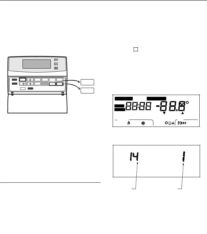
The Installer Setup is used to customize the thermostat to specific systems. Some of the options include temperature display, changeover and outdoor temperature display. Installer Setup numbers are listed in Table 6. The table includes all the configuration options and the factory-settings for the thermostat.
A combination of key presses are required to use the Installer Setup feature.
—To enter the Installer Setup, press and hold the Information i key with the increase ▲ and decrease ▼ keys until the first number is displayed. All display segments appear for approximately three seconds before the number is displayed. See Fig. 8 and 9.
—To advance to the next Installer Setup, press the Time ▲ key.
—To change a setting, use the increase ▲ or decrease ▼ key.
—To scroll the Installer Setup numbers backwards, press the Time ▼ key.
—To exit the Installer Setup, press Run Program.
Set Program Start Time Set Day/Time Temporary Setting Enrg
Hold for |
AM |
|
Sav |
|
Em Ht |
|
Room |
||
PM |
|
|||
Aux Ht |
|
%Humid |
||
|
|
|
||
MonTueWedThuFriSatSun |
Heat Cool |
Outdoor |
||
WakeLeaveReturnSleep |
|
In Recovery |
Auto |
Repl Batt |
System |
|
DST |
Fan |
|
Em Heat OffCool Auto |
Wait |
|
OnAuto |
|
M10345
Fig. 8. Display of all the segments of the LCD.
Temperature Settings
Refer to Table 5 for the default program. If the daytime energy savings period is not used, press the period key (Leave or Return) until the time is blank. The fan setting feature is available on select thermostat models. See Programming Section for complete instructions on changing the program.
Table 5. Default Program Settings.
|
|
Heat |
Cool |
Fan |
Period |
Time |
Setpoint |
Setpoint |
Setting |
|
|
|
|
|
Wake |
6:00 AM |
70°F |
78°F |
Auto |
|
|
(21°C) |
(25.5°C) |
|
|
|
|
|
|
Leave |
8:00 AM |
62°F |
85°F |
Auto |
|
|
(16.5°C) |
(29.5°C) |
|
|
|
|
|
|
Return |
6:00 PM |
70°F |
78°F |
Auto |
|
|
(21°C) |
(25.5°C) |
|
|
|
|
|
|
Sleep |
10:00 PM |
62°F |
82°F |
Auto |
|
|
(16.5°C) |
(28°C) |
|
|
|
|
|
|
INSTALLER SETUP
NOTE: For most applications, the thermostat factorysettings will not need to be changed. Review the factory settings in Table 6 and if no changes are necessary, go to the Installer System Test section.
INSTALLER SETUP |
FACTORY SETTING |
M10404 |
NUMBER DISPLAY |
OR OTHER CHOICE |
|
(COLUMN 2 |
DISPLAY (COLUMN 3 |
|
OF TABLE 6) |
OR 5 OF TABLE 6) |
|
Fig. 9. Display of Installer Setup number and setting.
 CAUTION
Heat pump and electric heat systems must be configured to 1 in Installer Setup number 2 to prevent equipment damage caused by the system running without the fan.
IMPORTANT
Only configurable numbers are shown on the device. Example: If thermostat does not have a system key, Installer Setup Number 12 will not be displayed.
Review Table 6 factory-settings and mark any desired changes in the Actual Settings column. When Installer Setup is complete, review the settings to confirm that they match the system.
7 |
68-0164—1 |

T8600D, T8601D AND T8602D CHRONOTHERM ® IV DELUXE PROGRAMMABLE THERMOSTATS
|
|
Table |
6. Thermostat Installer Setup Options. |
|
|
|||
|
|
|
|
|
|
|
|
|
|
Installer Setup |
|
|
|
|
Other Choices |
|
|
|
Number (Press |
|
|
|
|
|
|
|
|
Time ▲ key to |
Factory-Setting |
(Press ▲ or ▼ key to change) |
|
Actual |
|||
|
change) |
|
|
|
|
|
|
Setting |
Select |
Display |
|
Description |
Display |
Description |
|
||
|
|
|
|
|||||
|
|
|
|
|
|
|
|
|
Not used |
1 |
— |
|
— |
— |
— |
|
— |
|
|
|
|
|
|
|
|
|
Fan operationa |
2 |
0 |
|
Conventional |
1 |
Heat pump or electric heat |
|
|
|
|
|
|
applications where |
|
applications where thermostat |
|
|
|
|
|
|
equipment controls fan |
|
controls fan operation in heat |
|
|
|
|
|
|
operation in heat mode |
|
mode |
|
|
|
|
|
|
|
|
|
|
|
Not used |
3 |
— |
|
— |
— |
— |
|
— |
|
|
|
|
|
|
|
|
|
Heating cycle |
4 |
6 |
|
6—6 cph used for |
1, 3 or 9 |
1—1 cph used for radiant floor |
|
|
rate |
|
|
|
conventional heat |
|
heat, gravity system |
|
|
|
|
|
|
|
|
3—3 cph used for hot water |
|
|
|
|
|
|
|
|
systems or high efficiency |
|
|
|
|
|
|
|
|
furnaces |
|
|
|
|
|
|
|
|
9—9 cph used for electric heat |
|
|
|
|
|
|
|
|
systems |
|
|
|
|
|
|
|
|
|
|
|
Not used |
5 thru 11 |
— |
|
— |
— |
— |
|
— |
|
|
|
|
|
|
|
|
|
System setting |
12 |
1 |
|
Manual changeover |
0 or 2 |
0—Auto changeover |
|
|
adjustment |
|
|
|
|
|
2—Fixed auto changeover |
|
|
|
|
|
|
|
|
|
|
|
Adaptive |
13 |
0 |
|
Adaptive Intelligent |
1 |
Conventional recovery (system |
|
— |
Intelligent |
|
|
|
Recovery™ control is |
|
starts recovery at programmed |
|
|
Recovery™ |
|
|
|
activated (system |
|
time) |
|
|
control |
|
|
|
starts early so setpoint |
|
|
|
|
|
|
|
|
is reached by start of |
|
|
|
|
|
|
|
|
program period) |
|
|
|
|
|
|
|
|
|
|
|
|
|
Degree |
14 |
0 |
|
Temperature is |
1 |
Temperature is displayed in °C |
|
|
temperature |
|
|
|
displayed in °F |
|
|
|
|
display |
|
|
|
|
|
|
|
|
|
|
|
|
|
|
|
|
|
Not used |
15 |
— |
|
— |
— |
— |
|
— |
|
|
|
|
|
|
|
|
|
Clock format |
16 |
0 |
|
12-hour clock format |
1 |
24-hour clock format |
|
|
|
|
|
|
|
|
|
|
|
Not used |
17 and 18 |
— |
|
— |
— |
— |
|
— |
|
|
|
|
|
|
|
|
|
Extended fan |
19 |
0 |
|
No extended fan |
1 |
Fan operation is extended 90 |
|
|
operation in |
|
|
|
operation after the call |
|
seconds after the call for heat |
|
|
heatinga |
|
|
|
for heat ends |
|
ends. |
|
|
Extended fan |
20 |
0 |
|
No extended fan |
1 |
Fan operation is extended 90 |
|
|
operation in |
|
|
|
operation after the call |
|
seconds after the call for cool |
|
|
cooling |
|
|
|
for cool ends |
|
ends. |
|
|
|
|
|
|
|
|
|
|
|
Not used |
21 thru 23 |
— |
|
— |
— |
— |
|
— |
|
|
|
|
|
|
|
|
|
Outdoor |
24 |
0 |
|
No outdoor |
1 |
Outdoor temperature is |
|
|
temperature |
|
|
|
temperature is |
|
displayed. Needs a |
|
|
display (select |
|
|
|
displayed |
|
C7089B1000 Outdoor Sensor |
|
|
models) |
|
|
|
|
|
to operate |
|
|
|
|
|
|
|
|
|
|
|
Not used |
25 thru 29 |
— |
|
— |
— |
— |
|
— |
|
|
|
|
|
|
|
|
|
Deadband |
30 |
3 |
|
Heating and cooling |
4 thru 10 |
Heating and cooling setpoints |
|
|
|
|
|
|
setpoints can be set |
|
can be set no closer than the |
|
|
|
|
|
|
no closer than 3°F |
|
chosen value: |
|
|
|
|
|
|
(1.5°C) |
|
4—4°F (2°C) |
|
|
|
|
|
|
|
|
5—5°F (2.5°C) |
|
|
|
|
|
|
|
|
6—6°F (3°C) |
|
|
|
|
|
|
|
|
7—7°F (3.5°C) |
|
|
|
|
|
|
|
|
8—8°F (4°C) |
|
|
|
|
|
|
|
|
9—9°F (4.5°C) |
|
|
|
|
|
|
|
|
10—10°F (5°C) |
|
|
|
|
|
|
|
|
|
|
|
a Number 2 must be set to 1 to extend fan operation. |
|
|
|
|
||||
|
|
|
|
|
|
|
(continued) |
|
68-0164—1 |
8 |
T8600D, T8601D AND T8602D CHRONOTHERM ® IV DELUXE PROGRAMMABLE THERMOSTATS
|
Table |
6. Thermostat Installer Setup Options (continued). |
|
|||||
|
|
|
|
|
|
|
|
|
|
Installer Setup |
|
|
|
|
Other Choices |
|
|
|
Number (Press |
|
|
|
|
|
||
|
Time ▲ key to |
|
Factory-Setting |
(Press ▲ or ▼ key to change) |
Actual |
|||
|
change) |
|
|
|
|
|
Setting |
|
Select |
Display |
Description |
Display |
Description |
||||
|
|
|||||||
|
|
|
|
|
|
|
|
|
Not used |
31 and 32 |
— |
|
— |
— |
— |
— |
|
|
|
|
|
|
|
|
|
|
Minimum off time |
33 |
5 |
|
5 minute minimum off |
0 thru 4 |
Minimum number of minutes (0 |
|
|
for the |
|
|
|
time for the |
|
thru 5) the compressor will be |
|
|
compressor |
|
|
|
compressor |
|
off between calls for the |
|
|
|
|
|
|
|
|
compressor |
|
|
|
|
|
|
|
|
|
|
|
Temperature |
34 |
90 |
|
Highest setpoint |
40 to 89 |
Temperature range (1°F |
|
|
range stops in |
|
|
|
heating can be set to |
|
increments) heating setpoint |
|
|
heating |
|
|
|
|
|
can be set to |
|
|
|
|
|
|
|
|
|
|
|
Temperature |
35 |
45 |
|
Lowest setpoint |
46 to 99 |
Temperature range (1°F |
|
|
range stops in |
|
|
|
cooling can be set to |
|
increments) cooling setpoint |
|
|
cooling |
|
|
|
|
|
can be set to |
|
|
|
|
|
|
|
|
|
|
|
Not used |
36 |
— |
|
— |
— |
— |
— |
|
|
|
|
|
|
|
|
|
|
Temperature |
37 |
0 |
|
No difference in |
3 thru -3 |
1—Display adjusts to 1°F |
|
|
display |
|
|
|
displayed temperature |
|
higher than actual room |
|
|
adjustment |
|
|
|
and actual room |
|
temperature |
|
|
|
|
|
|
temperature |
|
2—Display adjusts to 2°F |
|
|
|
|
|
|
|
|
higher than actual room |
|
|
|
|
|
|
|
|
temperature |
|
|
|
|
|
|
|
|
3—Display adjusts to 3°F |
|
|
|
|
|
|
|
|
higher than actual room |
|
|
|
|
|
|
|
|
temperature |
|
|
|
|
|
|
|
|
-1—Display adjusts to 1°F lower |
|
|
|
|
|
|
|
|
than actual room temperature |
|
|
|
|
|
|
|
|
-2—Display adjusts to 2°F lower |
|
|
|
|
|
|
|
|
than actual room temperature |
|
|
|
|
|
|
|
|
-3—Display adjusts to 3°F lower |
|
|
|
|
|
|
|
|
than actual room temperature |
|
|
|
|
|
|
|
|
|
||
a Number 2 must be set to 1 to extend fan operation. |
|
|
|
|||||
IMPORTANT
Review the settings to confirm that they match the system. Press Run Program to exit the Installer Setup. The thermostat has saved the Installer Setup changes and initiated a reset in order to operate with these new settings. Be sure to set the current day and time immediately.
Setting Current Day and Time
1.Press Set Current Day/Time.
NOTE: On initial power up or after an extended power loss, 1:00 pm flashes on the display until a key is pressed.
Set Day/Time
Set Current |
|
|
|
|
|
|
PM |
Program |
Day/Time |
Time |
Wake |
Set Program |
Sleep |
Mon |
|
|
Leave Return |
||||||
|
Run |
Set Current |
|
|
|
|
|
Day/Time |
Hold Temp |
Day |
|
Settings |
System |
Fan |
|
|
|
|
|
Heat/Cool |
|
|
|
|
|
Daylight |
Copy |
|
|
|
|
|
|
Time |
|
|
|
|
M10312
2.Press Day until the current day is displayed.
NOTE: Sun=Sunday, Mon=Monday, Tue=Tuesday, Wed=Wednesday, Thu=Thursday, Fri=Friday, Sat=Saturday.
Set Day/Time
|
|
|
|
|
|
|
|
PM |
|
|
|
Time |
|
Set Program |
|
Tue |
|
Day |
Run |
Set Current |
|
Wake |
Leave |
Return |
Sleep |
|
Program |
Day/Time |
|
||||||
Hold Temp |
Day |
|
Heat/Cool |
|
System |
Fan |
|
|
|
|
Settings |
|
|
||||
|
|
Daylight |
Copy |
|
|
|
|
|
|
|
Time |
|
|
|
|
|
|
M10313
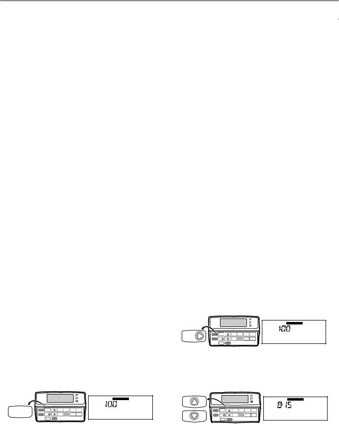
3.Press Time ▲ or Time ▼ until the current time is displayed.
NOTE: Tapping the Set Current Day/Time will change the time in one hour increments.
Time
Set Day/Time
AM
|
|
Time |
|
Set Program |
|
Tue |
|
Run |
Set Current |
|
Wake |
Leave |
Return |
Sleep |
|
Program |
Day/Time |
|
|||||
Hold Temp |
Day |
|
Heat/Cool |
|
System |
Fan |
|
|
Settings |
|
|
||||
|
Daylight |
Copy |
|
|
|
|
|
|
Time |
|
|
|
|
|
|
M10314
9 |
68-0164—1 |
Loading...