


D896 Automatic Vent Damper
GENERAL
D896 Automatic Vent Dampers are used with atmospheric type, gas-fired equipment to reduce home heating losses by closing off the vent between heat cycles.
PRODUCT DATA
FEATURES
•4-wire plug receptacle.
•Includes wiring harness on select models to fit plug receptacle onto S86/S8600/S8610/S8620 /L7148/L8148 or Penn Baso G60 or G66.
•For use only on atmospheric type gas-fired furnaces and boilers equipped with draft hoods.
•Applicable to direct spark ignition (DSI), intermittent pilot (IP), hot surface ignition (HSI), and standing pilot systems.
•Ambient temperature range 32°F (0°C) to 150°F (65°C).
•Requires dual automatic combination gas control valve or two separate single function main gas valves.
•Interlock switch provides safe operation; burner fires only with damper in open position.
•24V operation for easy, low-cost wiring.
•Visual indicator shows damper position.
•30-second nominal closing time for optimum energy savings.
•Quiet motor and relay.
•Wiring harnesses available separately to fit a variety of applications.
|
Contents |
General ............................................................................... |
1 |
Features .............................................................................. |
1 |
Specifications ...................................................................... |
2 |
Ordering Information ........................................................... |
2 |
Application ........................................................................... |
3 |
Installation ........................................................................... |
4 |
Settings ............................................................................... |
7 |
Operation and Checkout ..................................................... |
7 |
Troubleshooting ................................................................... |
8 |
Instructions to the Homeowner ........................................... |
9 |
ANSI Standards .................................................................. |
10 |
® U.S. Registered Trademark |
68-0186 |
Copyright © 1997 Honeywell Inc. • All Rights Reserved |

D896 AUTOMATIC VENT DAMPER
SPECIFICATIONS
IMPORTANT
The specifications given in this publication do not include normal manufacturing tolerances. Therefore, this unit might not exactly match the listed specifications. Also, this product is tested and calibrated under closely controlled conditions, and some minor differences in performance can be expected if those conditions are changed.
TRADELINE® Models
TRADELINE® models are selected and packaged to provide ease of stocking, ease of handling, and maximum replacement value. TRADELINE® model specifications are the same as those of standard models except as noted below.
TRADELINE® Models Available:
D896 Automatic Vent Damper with 4-wire plug receptacle.
Features:
•TRADELINE® pack with cross reference label.
•8 ft (2.4m), 4-wire cable with mating plug for D896 on one end and mating plug for 86/S8600/S8610/S8620 or Penn Baso G60 or G66 plug receptacle on the other end. Both ends equipped with an outlet box connector.
Standard Models
Models:
D896 Automatic Aluminized Vent Dampers: available in 4 in. to 9 in.
D896 Stainless Steel Vent Dampers: available in 10 in. to 12 in.
Actuator assembly includes motor, relay, interlock switch, safe-start circuit, and 4-pin plug receptacle. See Fig. 5.
Damper Size:
4, 5, 6, 7, 8, 9, 10, 11 and 12 in. diameter (102, 127, 152, 178, 203, 229, 254, 279 and 305 mm diameter).
Application:
For use only on Underwriters Laboratories Inc. listed and American Gas Association design certified atmospheric type, gas-fired furnaces and boilers equipped with a draft hood that has an outlet area no larger than the damper inlet area. Do not use with oil-fired furnace or boiler, power burner, or direct vent furnace or boiler. See Location and Mounting subsections in Installation section for additional application considerations.
Maximum Appliance Input Rating:
|
|
|
|
|
Nominal Damper |
Maximum Appliance |
|||
Outlet Diameter |
|
Input |
||
|
|
|
|
|
(in.) |
(mm) |
(Btuh) |
|
(W) |
|
|
|
|
|
4 |
102 |
95,000 |
|
27,835 |
|
|
|
|
|
5 |
127 |
148,000 |
|
43,364 |
|
|
|
|
|
6 |
152 |
212,000 |
|
62,116 |
|
|
|
|
|
7 |
178 |
290,000 |
|
84,970 |
|
|
|
|
|
8 |
203 |
377,000 |
|
110,461 |
|
|
|
|
|
9 |
229 |
475,000 |
|
139,175 |
|
|
|
|
|
10 |
254 |
590,000 |
|
173,500 |
|
|
|
|
|
11 |
280 |
715,000 |
|
210,300 |
|
|
|
|
|
12 |
305 |
942,000 |
|
277,000 |
|
|
|
|
|
Electrical Ratings:
Power Supply: 24 Vac, 60 Hz. Power:
Motor: 3.0 VA maximum. Relay: 0.1 VA maximum.
Contact Rating:
Relay: 10.0A at 250 Vac.
End Switch (Micro): 3.0A at 24 Vac.
Do not use with 120V or millivoltage, self-generating systems.
ORDERING INFORMATION
When purchasing replacement and modernization products from your TRADELINE® wholesaler or distributor, refer to the TRADELINE® Catalog or price sheets for complete ordering number.
If you have additional questions, need further information, or would like to comment on our products or services, please write or phone:
1.Your local Home and Building Control Sales Office (check white pages of your phone directory).
2.Home and Building Control Customer Logistics Honeywell Inc., 1885 Douglas Drive North Minneapolis, Minnesota 55422-4386
In Canada—Honeywell Limited/Honeywell Limitée, 35 Dynamic Drive, Scarborough, Ontario M1V 4Z9.
International Sales and Service Offices in all principal cities of the world. Manufacturing in Australia, Canada, Finland, France, Germany, Japan, Mexico, Netherlands, Spain, Taiwan, United Kingdom, U.S.A.
68-0186 |
2 |
D896 AUTOMATIC VENT DAMPER
NOTE: A minimum of a 30 VA transformer must be used when D896 is installed with S86/S8600/S8610/ S8620.
Electrical Connections:
Four-wire plug receptacle.
Thermostat Anticipator Setting:
0.13A.
Operating Times:
Approximate Damper Opening Time: 30 seconds. Approximate Damper Closing Time: 30 seconds.
Temperature Ratings:
Minimum Ambient: 32°F (0°C). Maximum Ambient: 150°F (66°C). Maximum Furnace Stack: 575°F (302°C).
Shipping: -20°F to +120°F (-29°C to +49°C).
Mounting: See Fig. 2.
Vertical Stack: Any orientation.
Horizontal Stack: The damper actuator must be on the left or right side of the vent.
IMPORTANT
Do not mount the vent damper with the actuator above or below the vent.
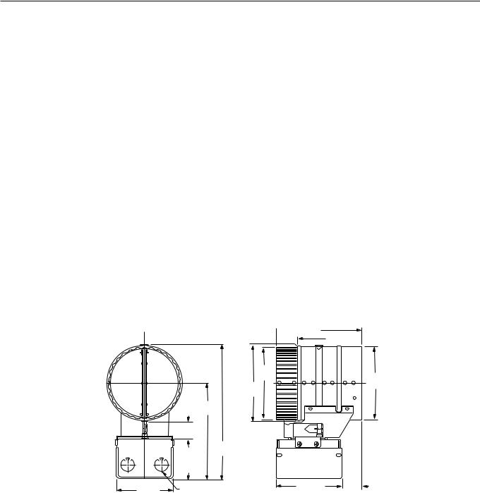
Dimensions:
See Fig. 1.
|
|
DIM. |
|
|
G |
1 |
1 |
(32) |
|
4 |
|
|
|
DIM. |
23 |
H |
|
|
4 |
|
(70)
Approvals:
American Gas Association Certified:
Certificate No. U-66-2A1.
Canadian Gas Association Design Certified:
1029AVD-9081.
Replacement Parts:
Damper Actuator is field replaceable without removing the damper assembly from the stack.
197516A Wiring Harness is a 4-wire cable, 8 feet (2.5 meters) long, with D896 mating plug on one end and mating plug for S86/S8600/S8610/S8620 or Penn Baso G60 or G66 on the other. An outlet box connector is on each end.
APPLICATION
The D896 Automatic Vent Damper is a 24 Vac, motorized stack damper. The damper closes off the furnace or boiler stack during the heating off-cycle. Use the D896 only on Underwriters Laboratories Inc. listed and American Gas Association design certified atmospheric type, gas-fired furnaces and boilers. The furnaces or boilers must be equipped with a draft hood that has an outlet area no larger than the damper inlet area. Do not use with oil-fired furnace or boiler, power burner, or direct vent furnace or boiler.
 DIM. F
DIM. E 
DIA
A DIA
DIA C
B
|
|
|
|
|
|
|
|
|
|
|
|
|
9 |
|
DIM. |
|
|
||
|
|
|
3 7 |
(98) |
|
7/8 DIA. STD. KNOCKOUT (3) |
|
4 16 (116) |
|
|
|||||||||
|
|
|
|
|
D |
|
|
|
|||||||||||
|
|
|
8 |
|
|
|
(ONE, OPPOSITE SIDE) |
|
|
|
|
|
|
|
|
|
|||
|
|
|
|
|
|
|
|
|
|
|
|
|
|
|
|
||||
|
|
|
|
|
|
|
|
|
|
|
|
|
|
|
|||||
BODY SIZE |
|
DIA. A |
|
DIA. B |
|
|
DIA. C |
DIM. D |
|
DIM. E |
|
DIM. F |
DIM. G |
DIM. H |
|||||
(REF) |
|
in. (mm) |
|
in. (mm) |
|
|
in. (mm) |
in. (mm) |
in. (mm) |
|
in. (mm) |
in. (mm) |
in. (mm) |
||||||
|
|
|
|
|
|
|
|
|
|
|
|
|
|
|
|
|
|
||
4 |
(102) |
3 |
15/16 (100) |
|
4 |
(102) |
|
4 |
1/16 (103) |
1 9/16 (40) |
4 |
1/2 (114) |
|
6 |
(152) |
6 |
3/4 (171) |
8 |
7/8 (225) |
5 |
(127) |
4 |
15/16 (125) |
|
5 |
(127) |
|
5 |
1/16 (129) |
1 9/16 (40) |
4 |
1/2 (114) |
|
6 |
(152) |
7 |
1/4 (184) |
9 |
7/8 (251) |
6 |
(152) |
5 |
15/16 (151) |
|
6 |
(152) |
|
6 |
1/16 (154) |
1 9/16 (40) |
4 |
1/2 (114) |
|
6 |
(152) |
7 |
3/4 (197) |
10 |
7/8 (276) |
7 |
(178) |
6 |
15/16 (176) |
|
7 |
(178) |
|
7 |
1/16 (179) |
3 3/16 (81) |
7 |
1/2 (191) |
|
9 |
(229) |
8 |
1/4 (209) |
11 |
7/8 (301) |
8 |
(203) |
7 |
15/16 (202) |
|
8 |
(203) |
|
8 |
1/16 (205) |
3 3/16 (81) |
7 |
1/2 (191) |
|
9 |
(229) |
8 |
3/4 (222) |
12 |
7/8 (327) |
9 |
(229) |
8 |
15/16 (224) |
|
9 |
(229) |
|
9 |
1/16 (230) |
3 3/16 (81) |
7 |
1/2 (191) |
|
9 |
(229) |
9 |
1/4 (235) |
13 |
7/8 (352) |
10 |
(254) |
9 |
15/16 (252) |
|
10 |
(254) |
|
10 |
1/16 (256) |
5 3/16 (132) |
11 |
1/2 (292) |
|
13 |
(330) |
9 |
3/4 (248) |
14 |
7/8 (378) |
11 |
(279) |
10 |
15/16 (278) |
|
11 |
(279) |
|
11 |
1/16 (281) |
5 3/16 (132) |
11 |
1/2 (292) |
|
13 |
(330) |
10 |
1/4 (260) |
15 |
7/8 (403) |
12 |
(305) |
11 |
15/16 (303) |
|
12 |
(305) |
|
12 |
1/16 (306) |
5 3/16 (132) |
11 |
1/2 (292) |
|
13 |
(330) |
10 |
3/4 (274) |
16 |
7/8 (428) |
|
|
|
|
|
|
|
|
|
|
|
|
|
|
|
|
|
|
|
M11381 |
Fig. 1. Installation dimensions in in. (mm).
3 |
68-0186 |
D896 AUTOMATIC VENT DAMPER
IMPORTANT
1.The atmospheric draft hood outlet area must be smaller or equal to the inlet area of the damper assembly.
2.If a second gas valve needs to be installed, refer to the gas valve manufacturer instructions for the procedure.
3.Using a dual automatic valve combination gas control or two separate gas valves is required with the D896.
4.Do not use with L8148 or L8124 with manual/ automatic switch because the switch can override the safety interlock in the system wiring and cause a hazardous condition.
5.Do not install on an appliance equipped with an automatic valve with a manual opener unless the manual opener is rendered inoperative or the automatic valve is replaced with an automatic valve without a manual opener.
6.On retrofit applications, installation identification label (provided) must be filled out by installer and applied to outside of cover.
INSTALLATION
When Installing this Product…
1.Read these instructions carefully. Failure to follow them could cause a hazardous condition.
2.Check the ratings given in the instructions and on the product to make sure the product is suitable for your application.
3.Installer must be a trained experienced service technician. The D896 must be installed in compliance with local codes or the Natural Gas Installation Code CAN/CGA-B149.1-B149.1-M91 and CSA C22.2 #3 Electrical Features of Fuel Burning Equipment, or the National Fuel Gas Code (ANSI Z223.1—NFPA 54) and the National Electrical Codes (ANSI C1—NFPA70). Use the ANSI Standard Z21.66-1994 included at the end of this specification during installation.
NOTE: In Canada, the damper is not certified for retrofit application. Certification for the suitability of the damper and appliance combination must be determined by the Canadian Gas Association.
4.Install only on an appliance connected to a factory built chimney or vent that complies with a recognized standard, or to a masonry or concrete chimney that is lined with a material acceptable to local code.
5.After installation is complete, check out product operation as provided in the Checkout section. See Exhibits A and B at the end of this specification.
 CAUTION
Can cause electrical shock or equipment damage.
1.Disconnect power supply.
2.Do not install within 6 in. (152 mm) of combustible materials.
3.Do not negate the action of any existing safety or operational control.
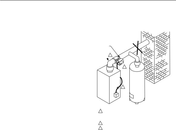
Location
The D896 must be installed after the furnace or boiler draft hood. See Fig. 2. Make sure the D896 Motor Actuator is readily visible and accessible. The damper must be located where air can freely circulate around it.
WARNING: DO NOT INSTALL THE
VENT DAMPER WITHIN 6 IN. (152 mm)
OF COMBUSTIBLE MATERIAL.
NO
D896 MOTOR
ACTUATOR
VENT PIPE
CURVE  2
2
DRAFT HOOD
1
CHIMNEY
3
FURNACE OR BOILER |
WATER HEATER |
1INSTALL THE VENT DAMPER TO SERVICE ONLY THE SINGLE APPLIANCE FOR WHICH IT IS INTENDED. IF IMPROPERLY INSTALLED, A HAZARDOUS CONDITION, SUCH AS AN EXPLOSION OR CARBON MONOXIDE POISONING, COULD RESULT.
2DO NOT INSTALL THE VENT DAMPER ON VENT PIPE CURVE.
3DO NOT RUN WIRES NEAR HIGH TEMPERATURE SURFACES.
USE STAND-OFF BRACKETS IF NECESSARY. |
M11370 |
Fig. 2. D896 location.
Do not install the D896:
—Where the stack temperature is higher than 575°F (284°C).
—Where the ambient temperature is higher than 150°F (66°C).
—In small or enclosed spaces where temperature can exceed 150° F (66°C). See WARNING following.
—On the vent pipe curve. See Fig. 2.
 WARNING
Severe illness or death possible. Prevent explosion or carbon monoxide poisoning.
Overheating can cause premature device failure. Be sure the D896 is used to control only one appliance.
Mounting
The damper must be mounted as close as possible to the draft hood without modifying the draft hood. The D896 can be mounted vertically or horizontally. When vertically mounting the vent damper, the motor actuator can be in any position. See Fig. 3.
Horizontal mounting requires the actuator to be located within 45 degrees directly above or directly below the horizontal diameter of the stack pipe. See Fig. 2 and 3.
68-0186 |
4 |
 Loading...