


OPERATOR’S
MANUAL
Manuel d’utilisation
Manual del operador
2500 PSI PRESSURE WASHER
Nettoyeur haute pression de 2 500 psi
Lavadora a presión de 2 500 psi
HL252300
Your pressure washer has been engineered and manufactured to our high standard for dependability, ease of operation, and operator safety. When properly cared for, it will give you years of rugged, trouble-free performance.
 WARNING: To reduce the risk of injury, the user must read and understand the operator’s manual before using this product.
Thank you for your purchase.
SAVE THIS MANUAL FOR FUTURE REFERENCE
Cenettoyeurhautepressionaétéconçuetfabriquéconformément aux strictes normes de fiabilité, simplicité d’emploi et sécurité d’utilisation. Correctement entretenu, il vous donnera des années de fonctionnement robuste et sans problème.
 AVERTISSEMENT : Pour réduire les risques de blessures, l’utilisateur doit lire et veiller à bien comprendre le manuel d’utilisation avant d’utiliser ce produit.
Merci de votre achat.
Su lavadora de presión ha sido diseñada y fabricada de conformidad con las estrictas normas para brindar fiabilidad, facilidad de uso y seguridad para el operador. Con el debido cuidado, le brindará muchos años de sólido y eficiente funcionamiento.
 ADVERTENCIA: Para reducir el riesgo de lesiones, el usuario debe leer y comprender el manual del operador antes de usar este producto.
Le agradecemos su compra.
CONSERVER CE MANUEL POUR |
|
GUARDE ESTE MANUAL PARA |
FUTURE RÉFÉRENCE |
|
FUTURAS CONSULTAS |
|
|
|

See this fold-out section for all of the figures referenced in the operator’s manual.
Consulter l’encart à volets afin d’examiner toutes les figures mentionnées dans le manuel d’utilisation.
Consulte esta sección desplegable para ver todas las figuras a las que se hace referencia en el manual del operador.
ii

Fig. 1
F
A
I
B
 H
H
J 


 G
G
C D
K
A - Fuel cap (bouchon de carburant, tapa del combustible)
B - Fuel tank (réservoir de carburant, tanque de combustible)
C - Oil cap/dipstick (bouchon/jauge d’huile , tapa del aceite con varilla de nivel)
D - Injection hose (d’injection transparent, manguera de inyección)
E - Engine switch (commutateur du moteur, interruptor del motor)
F - High pressure hose (manguera de alta presión)
G - Nozzle storage (buses et rangement de buse, boquillas y compartimientos para boquillas)
H - Handle (poignée, mango)
I- Trigger handle (poignée de gâchete, mango del gatillo)
J- Trigger with lock out (gâchette avec verouillage, gatillo con seguro)
K- Spray wand (lance de pulvérisation, tubo de rociado)
iii
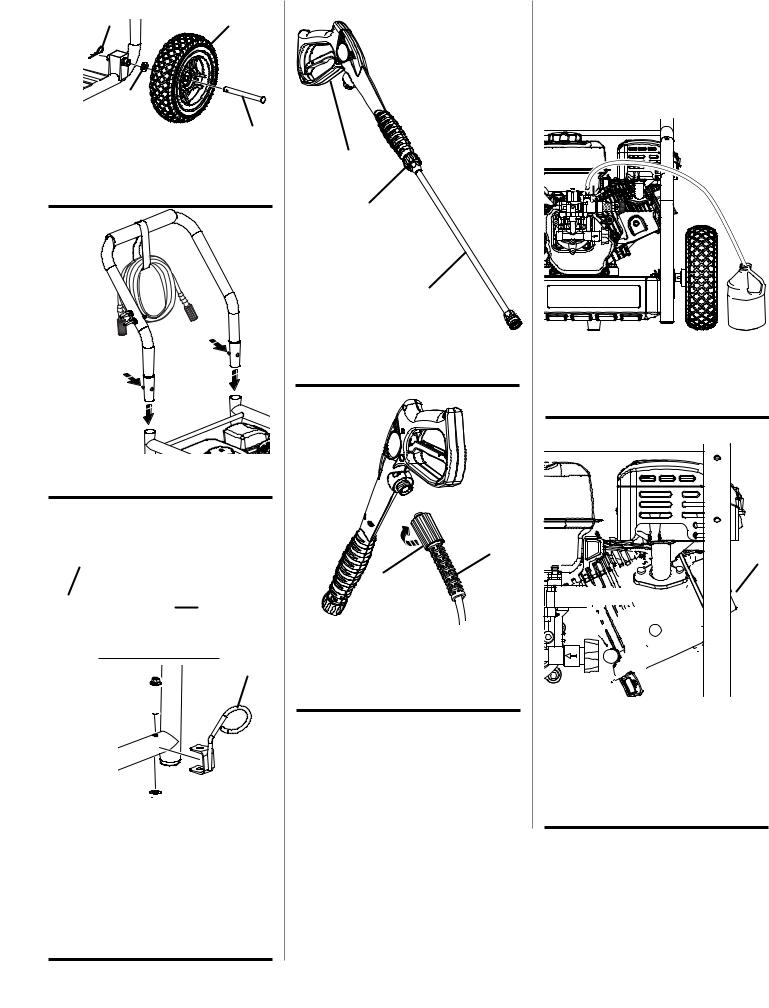
Fig. 2 |
D |
B |
|
||
|
C |
|
A - Axle (essieu, eje) |
A |
|
B - Wheel (disque, rueda) |
|
|
C - Washer (rondelle, conector) |
|
|
D - Hitch pin (goupille de sûreté, pasador del enganche)
Fig. 3
A
A
A - Push to insert (capuchon de verrouillage du manche, tapa de aseguramiento del mango)
Fig. 4
A B
D
C 

E 


A - Upper spray wand holder (support de la lance d’arrosage supérieur, soporte para el tubo rociador superior)
B - Lock nut (écrou de blocage, tuerca de seguridad)
C - Bolt (boulon, perno)
D - Lower spray wand holder (support de la lance d’arrosage inférieur, soporte para el tubo inferior)
E - Flange nut (écrou à embase, tuerca de brida)
Fig. 5
A
B
C
A - Trigger handle (poignée à gâchette, mango del gatillo)
B - Connector (connecteur, conector) C - Spray wand (lance de pulvérisation,
tubo de rociado)
Fig. 6
 B
B
C
A
A - Collar (collier, casquillo)
B - Inlet coupler (raccord d’entrée, acoplador de entrada)
C - High pressure hose (tuyau haute pression, manguera de alta presión)
iv
Fig. 7
A - Injection hose fitting (raccord du flexible d’injection, adaptador de la manguera de inyección)
B - Injection hose (flexible d’injection, manguera de inyección)
Fig. 8 |
A |
|
|
|
B |
|
C |
A - Threaded outlet (têton fileté, conexión roscada)
B - Collar (collier, casquillo)
C - High-pressure hose (flexible haute pression, manguera de alta presión)
Fig. 9
A |
B |
A - Water intake (rise d’eau, entrada de agua)
B - Garden hose (tuyau d’arrosage, manguera de jardín)
Fig. 10 |
A |
A - Oil cap/dipstick (bouchon / jauge d’huile, tapa del aceite con varilla de nivel)
Fig. 11
B
A - Funnel (entonnoir, embudo)
B - Fuel cap (bouchon du réservoir bouchon du réservoir, tapa del tanque de combustible)
Fig. 12 |
A |
A - Pump vent plug (Located behind nozzle storage panel), (bouchon d’aération de la pompe [qui se derrière supporte de buse], tapón de cierre de la tubería [situado detrás del soporte de limpieza])
Fig. 13
A
C BB
A - Fuel Valve (robinet de carburant, válvula de combustible)
B - ON position (marche, encendido) C - OFF position (arrêt, apagado)
Fig. 14
A
C B
A - Choke lever (levier d’étrangleur, palanca del anegador)
B - OFF (RUN) position (position RUN [marche], posición FUNCIONAMIENTO)
C - ON (COLD START) position (Position COLD START [démarrage à froid], posición de arranque en FRÍO)
v
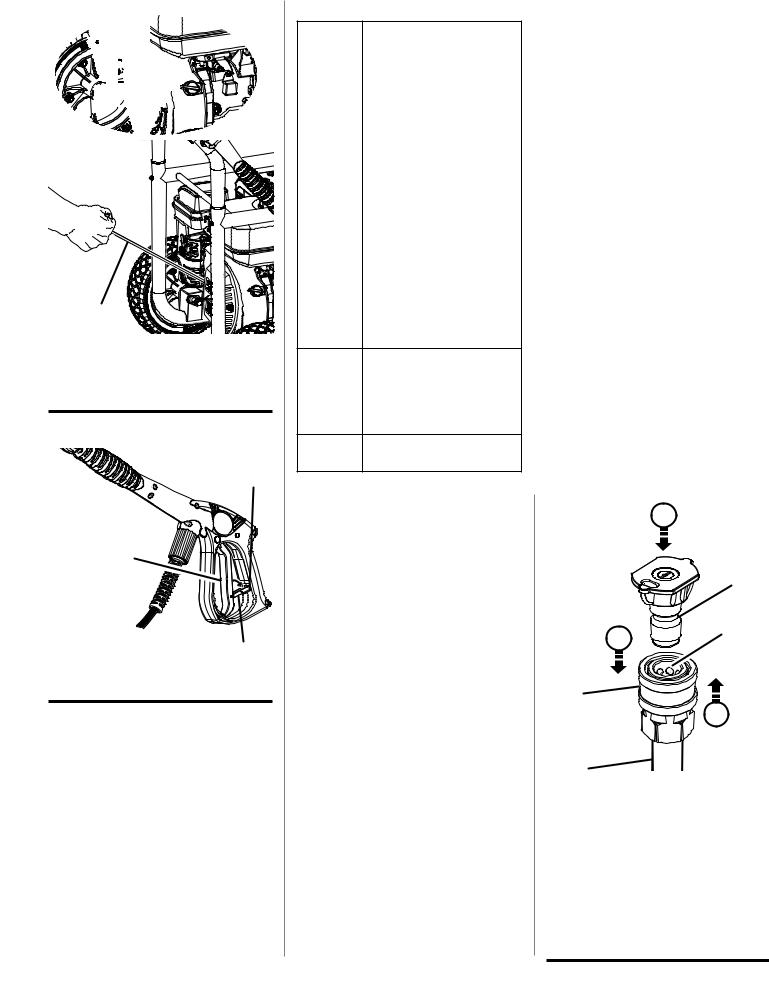
Fig. 15 |
B |
A
A - Recoil starter (lanceur à rappel, arrancador retráctil)
B - Engine switch (interrupteur du moteur, interruptor del motor)
Fig. 16
B
A
C
A - Trigger (gâchette, gatillo) B - Slot (fente, ranura)
C - Lock Out (bouton de verrouillage, seguro)
Fig. 17
Nozzle |
|
Application |
0º Red |
Spot cleaning of high, hard-to- |
|
|
reach areas |
|
|
• |
Removing caked-on mud |
|
|
from heavy construction, |
|
|
farm, or lawn equipment |
|
• |
Cleaning tar, glue, or stub- |
|
|
born stains from concrete |
|
• |
Cleaning overhead areas |
|
• Removingrustfromsteeland |
|
|
|
oxidation from aluminum |
25º Green |
For general purpose or large |
|
|
|
surfaces |
|
• Generalcleaningofdirt,mud, |
|
|
|
and grime |
|
• Cleaning roofs, gutters, and |
|
|
|
downspouts |
|
• |
Removing light mildew |
|
|
stains |
|
• Removing algae and bacteria |
|
|
|
build-up from pools |
|
• Rinsing surfaces in prepara- |
|
|
|
tion for painting |
40º White |
For wide-angle rinsing |
•Light cleaning and washing
•Washingandrinsingofpainted surfaces and boats
•Cleaning roofs, windows, patios, and driveways
Soap |
For all detergent applications |
(Black) |
|
Buse |
Application |
|
|
Buse |
Idéal pour nettoyer les taches situées |
rouge de |
dans les endroits en hauteur et |
0º |
difficiles d’accès |
|
• Pourretirerl’accumulationdeboue |
|
sur l’équipement lourd de ferme, |
|
de construction ou d’entretien des |
|
pelouses |
|
• Pourenleverlegoudron,lacolleou |
|
les taches tenaces sur le béton |
|
• Pour nettoyer les surfaces en |
|
surplomb |
|
• Pour enlever la rouille de l’acier et |
|
l’oxydation de l’aluminium |
Buse verte |
Pour une utilisation générale ou sur |
de 25º |
les grandes surfaces |
|
• Pour enlever la saleté et la boue |
|
• Pournettoyerlestoits,lesgouttières |
|
et les tuyaux de descente pluviale |
|
• Pour enlever les taches légères de |
|
moisissure |
|
• Pour retirer les algues et les |
|
bactéries accumulées sur les parois |
|
des piscines |
|
• Pour rincer les surfaces avant de |
|
les peindre |
Buse |
Pour un rinçage à large portée |
blanche de |
• Pour un nettoyage et un lavage en |
40º |
douceur |
|
• Pour laver et rincer les surfaces |
|
peintes et les bateaux |
|
• Pournettoyerlestoits,lesfenêtres, |
|
les patios et les entrées pavées |
Buse á |
Pour toutes les applications de |
détergente |
détergent |
(Noir) |
|
Boquilla |
|
Aplicaciones |
||
|
|
|||
0º Rojo |
Limpieza de puntos concentrados en |
|||
|
áreas altas y difíciles de alcanzar |
|||
|
• |
Eliminación |
de |
tierra seca |
|
|
proveniente de grandes equipos |
||
|
|
rurales, de construcción o de |
||
|
|
jardinería |
|
|
|
• |
Limpieza |
de |
alquitrán, |
|
|
p e g a m e n t o o a m a n c h a s |
||
|
|
persistentes de concreto |
||
|
• Limpieza de áreas elevadas |
|||
|
• Eliminación de herrumbre del |
|||
|
|
acero y de óxido del aluminio |
||
25º Verde |
Para usos generales o grandes |
|||
|
superficies |
|
|
|
|
• Limpieza general de suciedad y |
|||
|
|
tierra |
|
|
|
• Limpieza de techos, canalones |
|||
|
|
y bajantes |
|
|
|
• Eliminación de manchas ligeras |
|||
|
|
de moho |
|
|
|
• Eliminacióndealgasybacterias |
|||
|
|
acumuladas en piscinas |
||
|
• |
Enjuague de superficies en |
||
|
|
preparación para ser pintadas |
||
40º Blanco |
Para un ángulo amplio de |
|||
|
enjuague |
|
|
|
|
• Limpieza y lavado ligeros |
|||
|
• Lavadoyenjuaguedesuperficies |
|||
|
|
pintadas y botes |
|
|
|
• Limpieza de techos, ventanas, |
|||
|
|
patios y aceras |
|
|
|
|
|||
Boquilla |
Para todas las aplicaciones de |
|||
detergente |
detergente |
|
|
|
(Negra) |
|
|
|
|
|
|
|
|
|
|
|
|
|
|
Fig. 18 F
A
|
25 |
E |
B |
|
|
C |
|
|
G |
D |
|
A - Nozzle (embout, boquilla)
B - “Click” (déclic, hasta que trabe)
C - Quick-connect collar (casquillo de conexión rápida)
D - Spray wand (lance de pulvérisation, tubo de rociador)
E - Pull back the quick-connect collar (tirer la bague à connexion rapide, tire del collar de conexión rápida)
F- Push the nozzle into place (insérer en place la buse, introduzca la boquilla en su lugar)
G- Push the collar forward (poussez en avant la bague, empuje del collar adelante)
vi
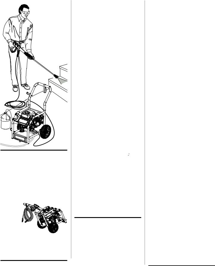
Fig. 19
Fig. 20
TO MOVE THE MACHINE DÉPLACEMENT DE LA MACHINE PARA MOVER LA MÁQUINA
Fig. 21
A
B
B
A - Filter cover (couvercle du filtre à air, tapa de la cámara de ventilación)
B - Foam filter (filtre, filtro)
Fig. 22
CHANGING LUBRICANT
VIDANGE DE LE LUBRIFIANT
CAMBIO DEL LUBRICANTE
Fig. 23
A
C
B
A - Spark plug wrench (clé à bougie, llave para bujía)
B - Spark plug cap (creux de la bougie, tapa ce la bujía)
C - Correct electrode gap (correct l’écartement des pointes d’électrode, correcta separación interelectródica)
Fig. 24
TO STORE THE MACHINE
REMISAGE DE LA MACHINE
PARA GUARDAR LA MÁQUINA
vii

TABLE OF CONTENTS
TABLE DES MATIÈRES / ÍNDICE DE CONTENIDO
Introduction....................................................................................................................................................................... |
2 |
Introduction / Introducción |
|
General Safety Rules......................................................................................................................................................... |
3 |
Règles de sécurité générales / Reglas de seguridad generales |
|
Specific Safety Rules........................................................................................................................................................ |
4 |
Règles de sécurité particulières / Reglas de seguridad específicas |
|
Symbols......................................................................................................................................................................... |
5-6 |
Symboles / Símbolos |
|
Features............................................................................................................................................................................ |
7 |
Caractéristiques / Características |
|
Assembly........................................................................................................................................................................ |
7-9 |
Assemblage / Armado................................................................................................................................................................ |
7-9 / 8-9 |
Operation..................................................................................................................................................................... |
9-12 |
Utilisation / Funcionamiento |
|
Maintenance............................................................................................................................................................... |
12-14 |
Entretien / Mantenimiento |
|
Troubleshooting............................................................................................................................................................... |
15 |
Dépannage / Solución de problemas |
|
Warranty..................................................................................................................................................................... |
16-17 |
Garantie / Garantía |
|
Parts Ordering and Service................................................................................................................................ |
Back Page |
Commande de pièces et réparation / Pedidos de piezas y servicio.......................................................... |
Page arrière / Pág. posterior |
introduction
Introduction / Introducción
This product has many features for making its use more pleasant and enjoyable. Safety, performance, and dependability have been given top priority in the design of this product making it easy to maintain and operate.
* * *
Ce produit offre de nombreuses fonctions destinées à rendre son utilisation plus plaisante et satisfaisante. Lors de la conception de ce produit, l’accent a été mis sur la sécurité, les performances et la fiabilité, afin d’en faire un outil facile à utiliser et à entretenir.
* * *
Este producto ofrece numerosas características para hacer más agradable y placentero su uso. En el diseño de este producto se ha conferido prioridad a la seguridad, el desempeño y la fiabilidad, por lo cual se facilita su manejo y mantenimiento.
Page 2 — English

important safety instructions
 WARNING:
Read and understand all instructions. Failure to follow all instructions listed below may result in electric shock, fire and/or carbon monoxide poisoning which will cause death or serious personal injury.
READ ALL INSTRUCTIONS
Know your tool. Read the operator’s manual carefully. Learn the machine’s applications and limitations as well as the specific potential hazards related to this tool.
Keep guards in place and in working order. Never operate the tool with any guard or cover removed. Make sure all guards are operating properly before each use.
Remove adjusting keys and wrenches. Form habit of checking to see that keys and adjusting wrenches are removed from tool before turning it on.
To reduce the risk of injury, keep children and visitors away. All visitors should wear safety glasses and be kept a safe distance from work area.
Keep the area of operation clear of all persons, particularly small children, and pets.
Do not operate the engine in a confined space where dangerous carbon monoxide fumes can collect. Carbon monoxide, a colorless, odorless, and extremely dangerous gas, can cause unconsciousness or death.
Use right tool. Don’t force tool or attachment to do a job it was not designed for. Don’t use it for a purpose not intended.
Dress properly. Do not wear loose clothing, gloves, neckties, or jewelry. They can get caught and draw you into moving parts. Rubber gloves and nonskid footwear are recommended when working outdoors. Also wear protective hair covering to contain long hair.
Do not operate the equipment while barefoot or when wearing sandals or similar lightweight footwear. Wear protective footwear that will protect your feet and improve your footing on slippery surfaces.
Exercise caution to avoid slipping or falling.
Always wear eye protection with side shields marked to comply with ANSI Z87.1. Following this rule will reduce the risk of serious personal injury.
Don’t overreach or stand on unstable support. Keep proper footing and balance at all times.
Use only recommended accessories. The use of improper accessories may cause risk of injury.
Follow the maintenance instructions specified in this manual.
Check damaged parts. Before further use of the tool, a guard or other part that is damaged should be carefully checked to determine that it will operate properly and perform its intended function. Check for alignment of moving parts, binding of moving parts, breakage of parts, mounting, and any other conditions that may affect its operation. A guard or other part that is damaged must be properly repaired or replaced by an authorized service center to avoid risk of personal injury.
Never leave tool running unattended. Turn power off.
Don’t leave tool until it comes to a complete stop.
Keep the engine free of grass, leaves, or grease to reduce the chance of a fire hazard.
Keep the exhaust pipe free of foreign objects.
Follow manufacturer’s recommendations for safe loading, unloading, transport, and storage of machine.
Be thoroughly familiar with controls. Know how to stop the product and bleed pressure quickly.
Keep tool dry, clean, and free from oil and grease.
Always use a clean cloth when cleaning. Never use brake fluids, gasoline, petroleum-based products, or any solvents to clean tool.
Stay alert and exercise control. Watch what you are doing and use common sense. Do not operate tool when you are tired. Do not rush.
Do not operate the product while under the influence of drugs, alcohol, or any medication.
Check the work area before each use. Remove all objects such as rocks, broken glass, nails, wire, or string which can be thrown or become entangled in the machine.
Do not use tool if switch does not turn it off. Have defective switches replaced by an authorized service center.
Before cleaning, repairing, or inspecting, shut off the engine and make certain all moving parts have stopped. Disconnect the spark plug wire, and keep the wire away from the plug to prevent accidental starting.
Avoid dangerous environment. Don’t use in damp or wet locations or expose to rain. Keep work area well lit.
Never use in an explosive atmosphere. Normal sparking of the motor could ignite fumes.
Do not operature while smoking or near an open flame.
Do not operate around dry brush, twigs, cloth rags, or other flammable materials.
WARNING: Risk of injection or injury – Do not direct discharge stream at persons.
Page 3 — English

SPECIFIC SAFETY RULES
Product users on United States Forest Service land, and in some states, must comply with fire prevention regulations. This product is not equipped with a spark arrestor; however, other user requirements may apply. Check with your federal, state, or local authorities. Before this engine is operated on any U.S. Forest Service regulated property, a spark arrestor must be installed.
Never direct a water stream toward people or pets, or any electrical device.
Before starting any cleaning operation, close doors and windows. Clear the area to be cleaned of debris, toys, outdoor furniture, or other objects that could create a hazard.
Never pick up or carry a machine while the engine is running.
Never start the machine if ice has formed in any part of the equipment.
Do not use acids, alkalines, solvents, flammable material, bleaches, or industrial grade solutions in this product. These products can cause physical injuries to the operator and irreversible damage to the machine.
Always operate the machine on a level surface. If the engine is on an incline, it could seize due to improper lubrication (even at the maximum oil level).
WARNING: High pressure jets can be dangerous if subject to misuse. The jet must not be directed at persons, animals, electrical devices, or the machine itself.
Never attempt to make any adjustments while the engine (motor) is running (except where specifically recommended by the manufacturer).
Protective covers must always cover rotating parts when the engine is running.
Keep cooling air intake (recoil starter area) and muffler side of the engine at least 3 feet away from buildings, obstructions, and other combustible objects.
Keep the engine away from flammables and other hazardous materials.
Keep away from hot parts. The muffler and other engine parts become very hot; use caution.
Do not touch the spark plug and ignition cable when starting and operating the engine.
Check fuel hoses and joints for looseness and fuel leakage before each use.
Check bolts and nuts for looseness before each use. A loose bolt or nut may cause serious engine problems.
Always refuel outdoors. Never refuel indoors or in a poorly ventilated area.
Never store the machine with fuel in the fuel tank inside a building where ignition sources are present, such as hot water and space heaters, clothes dryers, and the like.
If the fuel tank has to be drained, do this outdoors.
To reduce the risk of fire and burn injury, handle fuel with care. It is highly flammable.
Do not smoke while handling fuel.
Add fuel before starting the engine. Never remove the cap of the fuel tank or add fuel while the engine is running or when the engine is hot.
Loosen fuel cap slowly to release pressure and to keep fuel from escaping around the cap.
Replace all fuel tank and container caps securely.
Wipe spilled fuel from the unit. Move 30 feet away from refueling site before starting engine.
If fuel is spilled, do not attempt to start the engine but move the machine away from the area of spillage and avoid creating any source of ignition until fuel vapors have dissipated.
Never attempt to burn off spilled fuel under any circumstances.
Before storing, allow the engine to cool.
Store fuel in a cool, well-ventilated area, safely away from spark and/or flame-producing equipment.
Store fuel in containers specifically designed for this purpose.
Empty fuel tank and restrain the unit from moving before transporting in a vehicle.
When servicing use only identical replacement parts.
Use of any other parts may create a hazard or cause product damage.
Only use cold water.
Make sure minimum clearance of 3 feet is maintained from combustible materials.
Never spray close to the surface to be cleaned as you can damage the surface.
After stopping the engine, always pull the trigger on the trigger handle to relieve stored pressure in the high pressure hose. Failure to do so could result in serious personal injury.
Save these instructions. Refer to them frequently and use them to instruct other users. If you loan someone this tool, loan them these instructions also.
Page 4 — English
SYMBOLS
The following signal words and meanings are intended to explain the levels of risk associated with this product.
SYMBOL |
SIGNAL |
MEANING |
|
|
|
|
DANGER: |
Indicates an imminently hazardous situation, which, if not avoided, will result |
|
in death or serious injury. |
|
|
|
|
|
|
|
|
WARNING: |
Indicates a potentially hazardous situation, which, if not avoided, could result |
|
in death or serious injury. |
|
|
|
|
|
|
|
|
CAUTION: |
Indicates a potentially hazardous situation, which, if not avoided, may result in |
|
minor or moderate injury. |
|
|
|
|
|
|
|
|
CAUTION: |
(Without Safety Alert Symbol) Indicates a situation that may result in property |
|
damage. |
|
|
|
Some of the following symbols may be used on this product. Please study them and learn their meaning for safe operation of this product.
Symbol |
Name |
EXPLANATION |
|
Safety Alert |
Indicates a potential personal injury hazard. |
|
Read Operator’s Manual |
To reduce the risk of injury, user must read and understand |
|
operator’s manual before using this product. |
|
|
|
|
|
Eye Protection |
Always wear eye protection with side shields marked to comply |
|
with ansi z87.1. |
|
|
|
|
|
Wet Conditions Alert |
Do not expose to rain or use in damp locations. |
|
Hot Surface |
To reduce the risk of injury or damage, avoid contact with any |
|
hot surface. |
|
|
|
|
|
|
|
|
|
To reduce the risk of injection or injury, never direct a water |
|
|
|
|
|
|
|
|
|
||
|
|
|
|
|
Risk of Injections |
stream towards people or pets or place any body part in the |
|
|
|
|
|
|
|
stream. Leaking hoses and fittings are also capable of causing |
|
||
|
|
|
|
|
|
|
||
|
|
|
|
|
|
injection injury. Do not hold hoses or fittings. |
|
|
|
|
|
|
|
|
|
||
|
|
|
|
|
|
|
|
|
|
|
|
|
|
Risk of Explosion |
Fuel and its vapors are explosive and can cause severe burns |
|
|
|
|
|
|
|
|
|||
|
|
|
|
|
or death. |
|
||
|
|
|
|
|
|
|
||
|
|
|
|
|
|
|
|
|
|
|
|
|
|
|
|
|
|
|
|
|
|
|
Risk of Fire |
Fuel and its vapors are extremely flammable and explosive. Fire |
|
|
|
|
|
|
|
|
|||
|
|
|
|
|
can cause severe burns or death. |
|
||
|
|
|
|
|
|
|
||
|
|
|
|
|
|
|
|
|
|
|
|
|
|
|
|
|
|
|
|
|
|
|
|
Page 5 — English |
|
|
|
|
|
|
|
|
|
|
|
SYMBOLS
Some of the following symbols may be used on this product. Please study them and learn their meaning for safe operation of this product.
Symbol |
Name |
EXPLANATION |
Gas products emit carbon monoxide, an odorless, colorless, Toxic Fumes poison gas. Breathing carbon monoxide can cause nausea,
fainting, or death.
|
|
Kickback |
To reduce the risk of injury from kickback, hold the spray wand |
|
|
securely with both hands when the machine is on. |
|
|
|
|
|
|
|
|
|
|
|
|
|
|
|
Electric Shock |
Failure to use in dry conditions and to observe safe practices |
|
|
||
|
|
can result in electric shock. |
|
|
|
|
|
|
|
|
|
|
|
|
|
|
|
|
To reduce the risk of injury or damage, DO NOT USE ACIDS, |
|
|
|
|
|
|
Chemical Burns |
ALKALINES, BLEACHES, SOLVENTS, FLAMMABLE MATERIAL, |
|
|
|
OR INDUSTRIAL GRADE SOLUTIONS in this product. |
|
|
|
Page 6 — English

|
FEATURES |
|
|
|
|
|
|
|
|
|
|
|
|
|
|
PRODUCT SPECIFICATIONS |
|
|
|
Engine................................................................................................................................................................... |
179cc OHV |
||
Fuel Tank Capacity...................................................................................................................................................... |
0.96 gal |
||
Oil Capacity................................................................................................................................................................. |
20.3 oz. |
||
Maximum Pounds Per Square Inch Pressure*.......................................................................................................... |
2,500 psi |
||
Maximum Gallons Per Minute*................................................................................................................................... |
2.3 gpm |
||
Maximum Inlet Water Temperature................................................................................................................................. |
104˚F |
||
*Max. rating determined by PWMA Standard 101, when tested with red nozzle |
|
|
|
KNOW YOUR pressure washer
See Figure 1.
The safe use of this product requires an understanding of the information on the tool and in this operator’s manual as well as a knowledge of the project you are attempting. Before use of this product, familiarize yourself with all operating features and safety rules.
engine switch
The engine switch is used in combination with the recoil starter grip to start the engine. It is also used to turn the engine off.
recoil starter
The recoil starter is pulled to start the machine.
SOAP NOZZLE
The black soap nozzle is used to apply detergent at low pressure only.
SPARK ARRESTOR
This engine is not factory equipped with a spark arrestor. In some areas it is illegal to operate an engine without a spark arrestor. A spark arrestor is available by calling customer service for assistance.
Fuel tank
This fuel tank has a maximum capacity of 0.96 gal. Use unleaded automotive gasoline in the engine.
179cc OHV engine
This engine enables the pressure washer to achieve 2,500 psi (pounds per square inch) at a rate of 2.3 gpm (gallons per minute).
HOSE storage
Once the high pressure hose is rolled, hang it on the back of the machine using the hook-and-loop strap to secure in place.
THERMAL RELEASE VALVE
This pump feature will prevent water temperatures from reaching harmful levels by releasing a small amount of water. Once the water has drained, the thermal relief valve will reset itself.
trigger handle
The trigger handle has a gripping surface that provides added control of the spray wand and helps reduce fatigue.
trigger with lock out
Pulling the trigger releases a stream of water for high pressure cleaning. The lock out provides protection against unauthorized use.
ASSEMBLY
UNPACKING
This product requires assembly.
nCarefully remove the product and any accessories from the box. Make sure that all items listed in the packing list are included.
 WARNING:
Do not use this product if any parts on the Packing List are already assembled to your product when you unpack it. Parts on this list are not assembled to the product by the manufacturer and require customer installation. Use of a product that may have been improperly assembled could result in serious personal injury.
NOTE: This tool is heavy. To avoid back injury, lift with your legs, not your back, and get help when needed.
nInspect the tool carefully to make sure no breakage or damage occurred during shipping.
nDo not discard the packing material until you have carefully inspected and satisfactorily operated the tool.
nIf any parts are damaged or missing, please call 1-800-242-4672 for assistance.
Page 7 — English

ASSEMBLY
PACKING LIST
Pressure Washer
25 ft. High Pressure Hose Trigger Handle
Spray Wand Quick-connect Nozzles (4) Injection Hose
Injection Hose Filter Upper Spray Wand Holder Lower Spray Wand Holder Lock Nut
M8 10 mm Bolt
M8 13 mm Flange Nut
4-Cycle Engine Oil (SAE 30 or SAE 10W30)) Axle (2)
Hitch pins (2) Wheels (2) Handle Operator’s Manual
TOOLS NEEDED
13 mm Socket (9/16 in.)
10 mm Wrench (7/16 in.)
 WARNING:
If any parts are damaged or missing do not operate this tool until the parts are replaced. Use of this product with damaged or missing parts could result in serious personal injury.
 WARNING:
Do not attempt to modify this tool or create accessories not recommended for use with this tool. Any such alteration or modification is misuse and could result in a hazardous condition leading to possible serious personal injury.
 WARNING:
To prevent accidental starting that could cause serious personal injury, always disconnect the engine spark plug wire from the spark plug when assembling parts.
nPush the hitch pin into the hole on the end of the axle to secure the wheel assembly.
NOTE: The hitch pin should be pushed into the axle until the center of the pin rests on top of the axle.
nRepeat with the second wheel.
INSTALLing the handle
See Figure 3.
nPush and hold the push-pin button on the side of the handle as you slide the handle onto the frame.
NOTE: Before use, pull the handle up until the lock button snaps through the locking slots to secure the handle in place.
INSTALLing the UPPER AND LOWER
SPRAY WAND HOLDER
See Figure 4.
nPlace upper spray wand holder over the holes.
nAlign the lower bolt with the holes and push the bolt through.
nPlace the lock nut over the lower bolt and tighten securely.
nPlace lower spray wand holder over the holes.
nAlign the bolt with the holes and push the bolt through.
nHold flange nut with 13 mm wrench and bolt head with 10 mm socket. Tighten until the bolt is snug.
assembling the trigger handle
See Figure 5.
To attach the spray wand:
nPlace the threaded end of the spray wand in the connector on the end of the trigger handle.
nTurn the connector clockwise until it stops. This secures the spray wand in place.
connecting high pressure hose to TRIGGER HANDLE
See Figure 6.
nScrew the collar on the high pressure hose into the trigger handle inlet coupler by turning the hose collar clockwise.
nPull on the hose to be certain it is properly secured.
attaching the wheel assembly
See Figure 2.
nLocate the axle, hitch pins, washers, and wheels.
nSlide the axle through the hole in the center of the wheel.
nSlide the washer onto the axle.
nLift the machine and slide the axle into the wheel mounting hole in the machine base as shown.
attaching INJECTION hose
See Figure 7.
Before detergent can be used with this machine, the injection hose must be attached.
nPush the injection hose filter onto the end of the injection hose (if not already installed).
nPush the open end of the clear injection hose securely over the fitting.
NOTE: Keep injection hose away from hot surfaces.
Page 8 — English

assembly
connecting the high pressure hose to the pump
See Figure 8.
After the high pressure hose has been uncoiled and attached to the trigger handle:
nAlign the collar on the threaded outlet on the pump.
nInsert the hose on the end of the high pressure hose collar into the threaded outlet.
nTurn the collar clockwise to tighten the hose securely to the pump.
nPull on the hose to be certain it is properly secured.
connecting the garden hose to the pressure washer
See Figure 9.
The water supply must come from a water main. NEVER use hot water or water from pools, lakes, etc. Before connecting the garden hose to the pressure washer:
nRun water through the hose for 30 seconds to clean any debris from the hose.
nInspect the screen in the water intake.
nIf the screen is damaged, do not use the machine until the screen has been replaced.
nIf the screen is dirty, clean it before connecting the garden hose to the machine.
To connect the garden hose to the machine:
nUncoil the garden hose.
NOTE: There must be a minimum of 10 feet of unrestricted hose between the pressure washer intake and the hose faucet or shut off valve (such as a “Y” shut off connector).
nWith the hose faucet turned completely off, attach the end of the garden hose to the water intake. Tighten by hand.
operation
 WARNING:
Do not allow familiarity with tools to make you careless. Remember that a careless fraction of a second is sufficient to inflict serious injury.
 WARNING:
Always wear eye protection with side shields marked to comply with ANSI Z87.1. Failure to do so could result in objects being thrown into your eyes resulting in possible serious injury.
 WARNING:
Do not use any attachments or accessories not recommended by the manufacturer of this tool. The use of attachments or accessories not recommended can result in serious personal injury.
 WARNING:
Never direct a water stream toward people or pets, or any electrical device. Failure to heed this warning could result in serious injury.
Applications
You may use this tool for the purposes listed below:
Removing dirt and mold from decks, cement patios, and house siding
Cleaning boats, outdoor furniture, and grills
Page 9 — English

operation
adding/checking engine lubricant
See Figure 10.
NOTE: This machine has been shipped with approximately 2 oz. of lubricant in the engine from testing. You must add lubricant to the engine before starting it the first time.
CAUTION:
Any attempt to start the engine without adding lubricant will result in engine failure.
To add engine lubricant:
nPlace pressure washer on a flat, level surface.
nUnscrew the oil cap / dipstick by turning counterclockwise.
nUsing 4-stroke engine lubricant (SAE 30 or SAE 10W30), add engine lubricant until the fluid level rises to the hatched area on the dipstick (18 oz., 4-cycle engine lubricant provided). Do not overfill.).
nReplace the oil cap / dipstick and securely tighten.
NOTE: This engine has a total lubricant capacity of 20.3 oz. (0.6 qt.) .
To check engine lubricant level:
nSet pressure washer on a flat surface.
nWipe dipstick clean and re-seat in hole; do not rethread.
nRemove dipstick again and check lubricant level. Lubricant level should fall within the hatched area on the dipstick.
nIf level is low, add engine lubricant until the fluid level rises to the upper portion of the hatched area on the dipstick.
nReplace and secure the oil cap/dipstick.
 caution:
Do not overfill. Overfilling the crankcase may cause excessive smoke and engine damage.
OXYGENATED FUELS
DO NOT USE E85 FUEL. IT WILL VOID YOUR WARRANTY.
NOTE: Fuel system damage or performance problems resulting from the use of an oxygenated fuel containing more than the percentages of oxygenates stated below are not covered under warranty.
Ethanol. Gasoline containing up to 10% ethanol by volume (commonly referred to as E10) or 15% ethanol by volume (commonly referred to as E15) are acceptable. E85 is not.
adding gasoline to THE FUEL tank
See Figure 11.
 WARNING:
Gasoline and its vapors are highly flammable and explosive. To prevent serious personal injury and property damage, handle gasoline with care. Keep away from ignition sources, handle outdoors only, do not smoke while adding fuel, and wipe up spills immediately.
When adding gas to the pressure washer, make sure the unit is sitting on a flat, level surface. If the engine is hot, let the pressure washer cool before adding gas. Always fill the fuel tank outdoors with the machine turned off.
NOTE: Use unleaded gas only. Do not mix lubricant with gas.
nBefore removing the fuel cap, clean the area around it. Remove the fuel cap.
nInsert a clean funnel into the fuel tank then slowly pour gasoline into the tank. Fill tank to approximately 1-1/2 in. below the top of the tank neck (this allows for fuel expansion).
nReplace fuel cap and tighten until the cap “clicks”.
nClean up any spills before starting the engine.
pump lubricant
The pressure washer pump has been filled with sufficient lubricant at the factory. You do not need to check or add lubricant to the pump.
starting and stopping the pressure washer
See Figures 12 - 15.
caution:
Do not run the pump without the water supply connected and turned on.
NOTE: Remove the pump vent plug before first use.
Before starting the engine:
Connect all hoses.
Check all fluids (lubricant and gas).
Turn on the garden hose then pull the trigger to relieve air pressure; hold the trigger until a steady stream of water appears.
To start the engine:
nTurn the fuel valve to the ON position.
nMove the choke lever to the ON (COLD START) position.
NOTE: If the engine is warm, leave the choke lever in the ON (COLD START) position. Allow the engine to run for 5 seconds, and then push the choke to the RUN position.
Page 10 — English

operation
nPut the engine switch in the ON position.
nPull the recoil starter grip until the engine runs (a maximum of 6 times).
NOTE: Do not allow the grip to snap back after starting; return it gently to its original place.
nAllow the engine to run for 5 seconds, then push the choke lever to the RUN position.
To stop the engine:
nPut the engine switch in the OFF position.
nPull trigger to release water pressure.
using the spray wand trigger
See Figure 16.
For greater control and safety, keep both hands on the trigger handle at all times.
nPull back and hold the trigger to operate the pressure washer.
nRelease the trigger to stop the flow of water through the nozzle.
To engage the lock out:
nPush up on the lock out until it clicks into the slot.
To disengage the lock out:
nPush the lock out down and into its original position.
For the most effective cleaning, the spray nozzle should be between 8 in. and 24 in. from the surface to be cleaned. If the spray is too close it can damage the cleaning surface.
SELECTing the RIGHT NOZZLE FOR THE JOB
See Figures 17 - 18.
Each of the nozzles has a different spray pattern. Before starting any cleaning job, determine the best nozzle for the job. The following chart offers some general guidelines to help you choose the best nozzle for your application.
Nozzle |
Application |
|
|
0º Red |
Spot cleaning of high, hard-to-reach areas |
|
• Removing caked-on mud from heavy con- |
|
struction, farm, or lawn equipment |
|
• Cleaning tar, glue, or stubborn stains from |
|
concrete |
|
• Cleaning overhead areas |
|
• Removing rust from steel and oxidation |
|
from aluminum |
|
|
25º Green |
For general purpose or large surfaces |
|
• General cleaning of dirt, mud, and grime |
|
• Cleaning roofs, gutters, and downspouts |
|
• Removing light mildew stains |
|
• Removingalgaeandbacteriabuild-upfrom |
|
pools |
|
• Rinsing surfaces in preparation for |
|
painting |
40º White |
For wide-angle rinsing |
|
• Light cleaning and washing |
|
• Washing and rinsing of painted surfaces |
|
and boats |
|
• Cleaning roofs, windows, patios, and |
|
driveways |
|
|
Soap |
For all detergent applications |
(Black) |
|
|
|
 WARNING:
NEVER change nozzles without locking the lock out on the trigger handle and never point the wand at your face or at others. The quick-connect feature contains small springs that could eject the nozzle with some force. Failure to heed this may cause personal injury.
Using the quick-connect collar, changing nozzles is easy.
To connect a nozzle to the trigger handle:
nTurn off the pressure washer and shut off the water supply. Pull trigger to release water pressure.
nEngage the lock out on the trigger handle by pushing up on the lock out until it clicks into the slot.
nPush the nozzle into place in the quick-connect collar until it clicks into place and is secured properly.
To disconnect a nozzle from the trigger handle once the cleaning job is complete:
nTurn off the pressure washer and shut off the water supply. Pull trigger to release water pressure.
nEngage the lock out on the trigger handle by pushing up on the lock out until it clicks into the slot.
nRemove the nozzle by placing hand over nozzle then pulling back the quick-connect collar. Place nozzle in the nozzle storage area on the top of the machine.
Page 11 — English
 Loading...