


HR5 & HR7 ROTISSERIE
&
HW5 & HW7 WARMERS
MODELS |
|
HR5 |
|
auto. controls |
ML-126454 |
|
ML-126727 |
prog. controls |
ML-126456 |
|
ML-126728 |
HR7 |
|
auto. controls |
ML-126455 |
|
ML-126725 |
prog. controls |
ML-126457 |
|
ML-126726 |
HW5 |
ML-126207 |
HW7 |
ML-126208 |
I N S
TRUC T
I ONS
701 S. RIDGE AVENUE
TROY, OHIO 45374-0001
– 1 – |
FORM 34046 Rev. B (7-99) |

TABLE OF CONTENTS |
|
MODELS ............................................................................................................................................... |
4 |
GENERAL............................................................................................................................................. |
5 |
Features and Options .................................................................................................................... |
5 |
Ovens .............................................................................................................................................. |
6 |
Warmers ......................................................................................................................................... |
6 |
INSTALLATION .................................................................................................................................... |
7 |
Location .......................................................................................................................................... |
7 |
Legs / Casters ................................................................................................................................ |
7 |
Assembly ........................................................................................................................................ |
7 |
Assembling the Drip Plate ....................................................................................................... |
7 |
Assembling the Rotor (HR7 only)............................................................................................ |
8 |
Electrical Connections ................................................................................................................. |
10 |
Stacked Oven or Oven and Warmer ..................................................................................... |
10 |
Single Oven or Warmer ......................................................................................................... |
10 |
Electrical Data ........................................................................................................................ |
11 |
Before First Use ........................................................................................................................... |
12 |
OPERATION ...................................................................................................................................... |
12 |
Programmable Oven Control Panel With Manual Controls ....................................................... |
13 |
Manual Controls ........................................................................................................................... |
14 |
Using Manual Controls .......................................................................................................... |
14 |
Programmable Controls ............................................................................................................... |
15 |
Setting the Time of Day ......................................................................................................... |
15 |
Programming Menu Buttons .................................................................................................. |
16 |
Verifying Programmed Temperatures and Times ................................................................ |
16 |
Starting a Processing Cycle .................................................................................................. |
17 |
Displaying Time/Temperature During a Process Cycle ....................................................... |
17 |
Interrupting a Process Cycle ................................................................................................. |
17 |
End of Processing Cycle........................................................................................................ |
17 |
Changing a Programmed Setting .......................................................................................... |
17 |
Turning the Buzzer Off ........................................................................................................... |
18 |
Setting the End Time (Delayed Start) ................................................................................... |
18 |
Setting an Early Warning Buzzer .......................................................................................... |
18 |
Stopping the Rotisserie.......................................................................................................... |
18 |
Automatic Oven Control Panel With Manual Controls ............................................................... |
19 |
Manual Controls ........................................................................................................................... |
20 |
Using Manual Controls .......................................................................................................... |
20 |
© HOBART CORPORATION, 1999 |
– 2 – |

Automatic Controls ....................................................................................................................... |
21 |
Setting the Temperature ........................................................................................................ |
21 |
Setting the Roasting Time ..................................................................................................... |
21 |
Setting an Early Warning Buzzer .......................................................................................... |
22 |
Setting End Time (Delayed Start) ......................................................................................... |
22 |
Interrupting an Automatic Cooking Operation ...................................................................... |
22 |
Stopping an Automatic Cooking Operation .......................................................................... |
23 |
Changing a Setting ................................................................................................................ |
23 |
Stopping the Rotisserie.......................................................................................................... |
23 |
Setting the Time of Day ......................................................................................................... |
23 |
Turning the Buzzer Off ........................................................................................................... |
23 |
Resetting the Automatic Controls ......................................................................................... |
23 |
Preparing the Product .................................................................................................................. |
24 |
Loading Products Onto Accessories ........................................................................................... |
24 |
Loading Products onto Spits ................................................................................................. |
24 |
Loading Products onto Chicken Racks ................................................................................. |
25 |
Loading Products in a Basket................................................................................................ |
26 |
Loading Accessories Into Oven .................................................................................................. |
27 |
Loading Spits Into Oven ........................................................................................................ |
28 |
Loading Fork Spits Into Oven ................................................................................................ |
28 |
Loading Racks, Baskets, or Backing Plates Into Oven ....................................................... |
29 |
Unloading Accessories From Oven ............................................................................................ |
29 |
Suggestive Roasting Guidelines ................................................................................................. |
30 |
Emptying Grease Drawer ............................................................................................................ |
31 |
Warmer Controls .......................................................................................................................... |
32 |
Using Warmers (Models HW5 and HW7) ................................................................................... |
32 |
CLEANING ......................................................................................................................................... |
33 |
Cleaning Stainless Steel Surfaces .............................................................................................. |
33 |
Cleaning Nonstick Coated Surface ............................................................................................. |
33 |
How To Clean Nonstick Coated Surfaces (Routine Cleaning) ............................................ |
34 |
How to Clean Severe Buildup on Nonstick Coated Surfaces .............................................. |
34 |
Cleaning Probe ............................................................................................................................ |
34 |
Cleaning Grease Drawer ............................................................................................................. |
35 |
Cleaning Warmers ....................................................................................................................... |
35 |
Cleaning Quartz Lamps ............................................................................................................... |
35 |
Monthly Cleaning ......................................................................................................................... |
35 |
MAINTENANCE ................................................................................................................................. |
36 |
Model HR5 Only ........................................................................................................................... |
36 |
Service .......................................................................................................................................... |
36 |
– 3 –

Model HR5 Oven |
Model HR7 Oven |
Model HW5 Warmer |
Model HW7 Warmer |
Model HR5 Oven/HW5 Warmer |
Model HR7 Oven/HW7 Warmer |
• Rotisserie Ovens with Programmable Controls shown; Meat probe not shown.
– 4 –

Installation, Operation and Care of
HR SERIES ROTISSERIE OVENS AND
HW SERIES ROTISSERIE WARMERS
PLEASE KEEP THIS MANUAL FOR FUTURE REFERENCE
GENERAL
The Hobart HR Series Rotisserie Ovens and HW Series Rotisserie Warmers feature full view tempered glass doors, both front and back, and quartz lighting that promotes visual appeal and stimulates customer interest. They also feature a stainless steel interior and exterior for ease of cleaning.
Ovens and Warmers are available in two sizes:
HR5 — Oven with five spits (15-20 chickens)
HW5 — Warming cabinet
HR7 — Large oven with seven spits (28-35 chickens)
HW7 — Warming cabinet
Features and Options
Quantity Required per Oven
|
|
Spit |
Basket |
Turkey Spit |
Baking Plate |
Chicken Rack |
Meat Forks |
Warmer Shelves |
|
||
|
|
|
|
|
|
3 rack |
4 rack |
5 rack |
|
|
|
|
|
|
|
|
|
|
|
|
|
|
|
|
HR5 |
5 std. |
5 opt. |
1 opt. |
5 opt. |
5 opt. |
NA |
NA |
5 opt. |
NA |
|
|
|
|
|
|
|
|
|
|
|
|
|
|
HR7 |
7 std. |
7 opt. |
1 opt. |
NA |
NA |
7 opt. |
7 opt. |
7 opt. |
NA. |
|
|
|
|
|
|
|
|
|
|
|
|
|
|
HW5 |
NA |
NA |
NA |
NA |
NA |
NA |
NA |
NA |
3 std. |
|
|
|
|
|
|
|
|
|
|
|
|
|
|
HW7 |
NA |
NA |
NA |
NA |
NA |
NA |
NA |
NA |
3 std. |
|
|
|
|
|
|
|
|
|
|
|
|
|
DO NOT mix accessories on the rotor.
Stacking kits are available to stack ovens or stack an oven and warmer. You must stack the same size oven and warmer. Refer to the Stacking Kit Installation Instructions (F-24860) for further information.
– 5 –

OVENS
There are two types of oven control operations:
•Programmable with Manual control operation
•Automatic with Manual control operation
When you purchase your rotisserie oven you have the option of ordering the rotor, drip plates, and some accessories with either a nonstick coated surface or stainless steel surface. Refer to the next page to assemble the drip plate and rotor.
The HR ovens use self-basting spits with optional flat baking racks, meat forks, or baskets. The rotation of the spits, racks, or baskets with the combination convection and radiant heat provide thorough cooking and even browning in the oven. The oven's grease drawer has a drain valve for elimination of excess fat and can be completely removed for cleaning.
WARMERS
The HW warmers feature low velocity, high humidity air circulation which keeps foods moist. The HW warming cabinets have three shelves.
– 6 –
INSTALLATION
Immediately after unpacking the oven, check for possible shipping damage. If oven is found to be damaged after unpacking, save the packaging material and contact the carrier within 15 days of delivery.
Prior to installation, test the electrical service to assure that it agrees with the specifications on the machine data plate located on the right side panel near the controls.
LOCATION
The oven may be placed where cooking may be observed to enhance customer awareness, but must be installed on a level surface if the oven or warmer is not on casters.
The installation location must allow adequate clearances for servicing and for proper operation of the front and rear doors.
•A minimum wall clearance of 10" (254 mm) from any glass, and 4" (101.6 mm) from each side panel must be maintained.
LEGS / CASTERS
Each oven and warmer is furnished on 19⁄16" (39.7 mm) legs. Casters are included with the stacking kit.
ASSEMBLY
The drip plate and rotor come in a separate boxed kit with either a nonstick coated surface or stainless steel surface. They must be assembled at installation.
CAUTION: Special care must be taken when assembling coated parts. Any abrasion reduces the life of the coated parts.
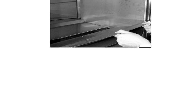
Assembling the Drip Plate
Place the two bottom drip plates in oven. The two plates slant to the middle to allow fat to drip into the grease drawer (Fig.1).
PL-41161
Fig. 1
– 7 –
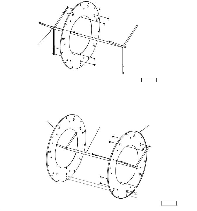
Assembling the Rotor (HR7 only)
You should have: (2) rotor end plates; (1) rotor shaft; (12) screws
1.Face the two rotor end plates against each other to make sure the holes match. This is done to ensure you have a matched set of rotor end plates. If holes do not match, the accessories will not align properly.
2.Align the holes on the left rotor end plate (as you face the rotor) with the holes on one side of the rotor shaft.
3.Secure the rotor end plate to the rotor shaft with the screws available (Fig. 2).
LEFT HAND
 ROTOR END PLATE
ROTOR SHAFT
HR7 |
|
Fig. 2 |
PL-53376 |
|
4.Assemble the right rotor end plate (as you face the rotor).
5.Align the hole pattern with the assembled left rotor end plate as indicated by the dotted lines shown below (Fig. 3). This is done to ensure the rotor end plate is in the correct position.
6.Repeat steps 2 and 3 to secure the right rotor end plate.
LEFT HAND
ROTOR END PLATE
RIGHT HAND
ROTOR SHAFT
ROTOR END PLATE
HR7
Fig. 3
PL-53377
– 8 –
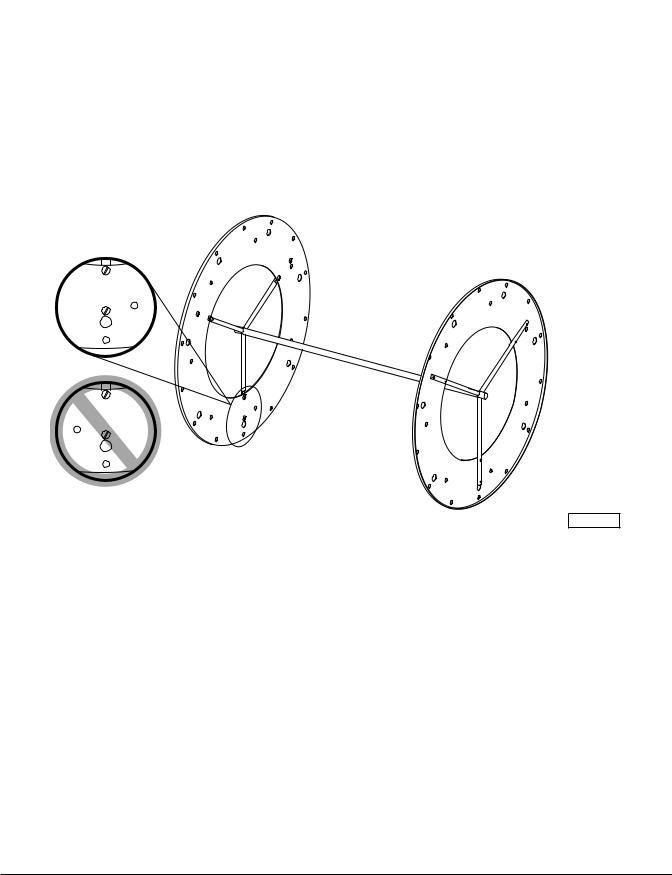
7.Place the assembled rotor in the oven.
8.Turn Rotisserie dial to
 to rotate rotor.
9.Turn Rotisserie dial to "0/P" to stop rotation when the hole pattern (Fig. 4) is located at the bottom of the oven.
10.Verify that the hole pattern is identical to the top illustrated hole pattern shown in Fig. 4.
11.If hole pattern does not match the top illustrated hole pattern, but does match the bottom illustrated hole pattern in Fig. 4:
a.Take rotor assembly out of oven.
b.Flip rotor assembly.
c.Place rotor assembly back in oven.
d.Repeat steps 8-10 above.
HR7
Fig. 4 |
PL-53381 |
– 9 –

ELECTRICAL CONNECTIONS
WARNING: ELECTRICAL AND GROUNDING CONNECTIONS MUST COMPLY WITH THE APPLICABLE PORTIONS OF THE NATIONAL ELECTRICAL CODE AND/OR OTHER LOCAL ELECTRICAL CODES.
WARNING: DISCONNECT ELECTRICAL POWER SUPPLY AND PLACE A TAG AT THE DISCONNECT SWITCH INDICATING THAT YOU ARE WORKING ON THE CIRCUIT.
WARNING: APPLIANCES EQUIPPED WITH A FLEXIBLE ELECTRIC SUPPLY CORD ARE PROVIDED WITH A THREE-PRONG GROUNDING PLUG. THIS PLUG MUST BE CONNECTED INTO A PROPERLY GROUNDED THREE-PRONG RECEPTACLE. IF THE RECEPTACLE IS NOT THE PROPER GROUNDING TYPE, CONTACT AN ELECTRICIAN. DO NOT REMOVE THE GROUNDING PRONG FROM THIS PLUG.
Access the electrical connection point by removing the side panel(s) where the controls are located. Ensure that the electrical power supply agrees with the specifications on the oven's data plate and complies with the wiring diagram, located behind the oven side panel and under the drive motor.
Stacked Ovens or Oven and Warmer
Refer to the Stacking Kit Installation Instruction (F-24860) included with your stacking kit.
Single Oven or Warmer
1.Remove the side panels.
2.At the same time attach power leads to oven or warmer terminal block as shown on the wiring diagram, located behind the side panel and under the drive motor, and attach the power supply conduit to the bottom of the oven or warmer.
3.Attach power supply leads to line side of the terminal block.
4.Inspect and check all wiring and terminal connections for tightness and proper routing away from any moving parts or pinch points.
5.Carefully replace the side panels.
Refer to the Electrical Data chart on the next page.
– 10 –
ELECTRICAL DATA
MODEL |
VOLTS |
HERTZ |
PHASE |
CIRCUIT SIZE* |
|
|
|
|
(AMPS) |
|
|
|
|
|
HR5 |
208 |
60 |
1 |
35 |
|
208 |
60 |
3 |
20 |
|
240 |
60 |
1 |
35 |
|
240 |
60 |
3 |
20 |
|
|
|
|
|
HR7 |
208 |
60 |
1 |
60 |
|
208 |
60 |
3 |
35 |
|
240 |
60 |
1 |
60 |
|
240 |
60 |
3 |
35 |
|
|
|
|
|
HW5 |
208 |
60 |
1 |
15 |
|
208 |
60 |
3 |
10 |
|
240 |
60 |
1 |
15 |
|
240 |
60 |
3 |
10 |
|
|
|
|
|
HW7 |
208 |
60 |
1 |
15 |
|
208 |
60 |
3 |
15 |
|
240 |
60 |
1 |
20 |
|
240 |
60 |
3 |
15 |
|
|
|
|
|
STACKED MODELS |
|
|
|
|
|
|
|
|
|
(2) HR5 |
208 |
60 |
1 |
70 |
|
208 |
60 |
3 |
40 |
|
240 |
60 |
1 |
70 |
|
240 |
60 |
3 |
45 |
|
|
|
|
|
(2) HR7 |
208 |
60 |
3 |
70 |
|
240 |
60 |
3 |
70 |
|
|
|
|
|
(2) HW5 |
208 |
60 |
1 |
30 |
|
208 |
60 |
3 |
- |
|
240 |
60 |
1 |
35 |
|
240 |
60 |
3 |
- |
|
|
|
|
|
(2) HW7 |
208 |
60 |
1 |
30 |
|
208 |
60 |
3 |
25 |
|
240 |
60 |
1 |
40 |
|
240 |
60 |
3 |
30 |
|
|
|
|
|
HR5 & HW5 |
208 |
60 |
1 |
50 |
|
208 |
60 |
3 |
40 |
|
240 |
60 |
1 |
50 |
|
240 |
60 |
3 |
40 |
|
|
|
|
|
HR7 & HW7 |
208 |
60 |
1 |
80 |
|
208 |
60 |
3 |
50 |
|
240 |
60 |
3 |
80 |
|
240 |
60 |
1 |
50 |
|
|
|
|
|
*Maximum Circuit Breaker Size / Minimum Circuit Amperage compiled in accordance with the National Electrical Code, 1990 edition.
– 11 –
 Loading...