


MODELS HO300G AND HO300E MINI ROTATING RACK OVENS
MODEL |
|
HO300E (ELECTRIC) |
ML-132177 |
HO300G (GAS) |
ML-132178 |
701 S. RIDGE AVENUE
TROY, OHIO 45374-0001
937 332-3000
www.hobartcorp.com |
FORM 36705 (Oct. 2005) |

IMPORTANT FOR YOUR SAFETY
THIS MANUAL HAS BEEN PREPARED FOR PERSONNEL QUALIFIED TO INSTALL GAS EQUIPMENT, WHO SHOULD PERFORM THE INITIAL FIELD START-UP AND ADJUSTMENTS OF THE EQUIPMENT COVERED BY THIS MANUAL.
POST IN A PROMINENT LOCATION THE INSTRUCTIONS TO BE FOLLOWED IN THE EVENT THE SMELL OF GAS IS DETECTED. THIS INFORMATION SHOULD BE OBTAINED FROM THE LOCAL GAS SUPPLIER.
IMPORTANT
IN THE EVENT A GAS ODOR IS DETECTED, SHUT DOWN
UNITS AT MAIN SHUTOFF VALVE AND CONTACT THE LOCAL
GAS COMPANY OR GAS SUPPLIER FOR SERVICE.
FOR YOUR SAFETY
DO NOT STORE OR USE GASOLINE OR OTHER FLAMMABLE
VAPORS OR LIQUIDS IN THE VICINITY OF THIS OR ANY
OTHER APPLIANCE.
WARNING: IMPROPER INSTALLATION, ADJUSTMENT,
ALTERATION, SERVICE OR MAINTENANCE CAN CAUSE
PROPERTY DAMAGE, INJURY OR DEATH. READ THE
INSTALLATION, OPERATING AND MAINTENANCE
INSTRUCTIONS THOROUGHLY BEFORE INSTALLING OR
SERVICING THIS EQUIPMENT.
IN THE EVENT OF A POWER FAILURE, DO NOT ATTEMPT TO
OPERATE THIS DEVICE.
KEEP AREA AROUND OVEN CLEAR OF COMBUSTIBLES. DO
NOT OBSTRUCT COMBUSTION AND VENTILATION OPENINGS
ON THE OVEN.
This manual has been prepared to provide information in accordance with
ANSI Z83.11-2004 for gas equipment.
© HOBART, 2005 |
– 2 – |

TABLE OF CONTENTS |
|
GENERAL ............................................................................................................................................. |
4 |
INSTALLATION .................................................................................................................................... |
4 |
Unpacking ........................................................................................................................................ |
4 |
Location ............................................................................................................................................ |
5 |
Installation Codes and Standards ................................................................................................... |
5 |
Assembly.......................................................................................................................................... |
5 |
Gas Connections ............................................................................................................................. |
6 |
Testing the Gas Supply System ..................................................................................................... |
6 |
Ventilation ......................................................................................................................................... |
6 |
Plumbing Connections..................................................................................................................... |
6 |
Drain Connections ........................................................................................................................... |
7 |
Electrical Connections .................................................................................................................... |
7 |
OPERATION......................................................................................................................................... |
8 |
Controls ............................................................................................................................................ |
8 |
Setting Clock .................................................................................................................................. |
11 |
Basic Operation ............................................................................................................................. |
12 |
Food Service Steam Mode ............................................................................................................ |
14 |
Safety Alarm................................................................................................................................... |
14 |
Programming the Oven ................................................................................................................. |
15 |
Using the Programs ....................................................................................................................... |
18 |
Customized Operation................................................................................................................... |
19 |
Shutdown........................................................................................................................................ |
22 |
Cleaning ......................................................................................................................................... |
22 |
ACCESSORIES - HPC800 PROOFING CABINET ......................................................................... |
23 |
Plumbing connections ................................................................................................................... |
23 |
Drain connections .......................................................................................................................... |
23 |
Electrical Connections .................................................................................................................. |
23 |
Dimensions and Service Connection Diagram ............................................................................ |
24 |
Controls .......................................................................................................................................... |
25 |
MAINTENANCE .................................................................................................................................. |
26 |
General ........................................................................................................................................... |
26 |
Parts and Service Information ...................................................................................................... |
26 |
TROUBLESHOOTING ....................................................................................................................... |
27 |
Burners Will Not Light (Gas Ovens Only).................................................................................... |
27 |
Safety Alarm................................................................................................................................... |
27 |
Circulation Motor ............................................................................................................................ |
27 |
Parts and Service Information ...................................................................................................... |
27 |
OWNER PREVENTIVE MAINTENANCE PROCEDURES............................................................. |
28 |
Introduction..................................................................................................................................... |
28 |
Preventive Maintenance Procedures ........................................................................................... |
28 |
– 3 –

OPERATION AND CARE OF
MODELS HO300G AND HO300E MINI ROTATING
RACK OVENS
KEEP THIS MANUAL FOR FUTURE USE
GENERAL
Models HO300G (Gas) and HO300E (Electric) Mini Rotating Rack Ovens feature the choice of two rack configurations:
•Eight 18" x 26" (45.7 cm x 66 cm) pan capacity rack with 4" (10.2 cm) slide spacing
•Six 18" x 26" (45.7 cm x 66 cm) pan capacity rack with 5.31" (13.5 cm) slide spacing
Both oven rack options can be ordered in an end-load or side-load design. A mechanism in the ceiling rotates the rack during baking.
Model HO300G is rated at 95,000 BTU/hr (natural or propane gas). Model HO300E is rated at 18.0 kW (electric).
Hobart Mini Rotating Rack Ovens are produced with quality workmanship and material. Proper installation, usage and maintenance of the rack oven will result in years of satisfactory performance.
It is suggested that you thoroughly read this manual and carefully follow the instructions provided.
INSTALLATION
In order to validate the warranty, the start-up must be performed by an Authorized Service Representative. Before installing, verify that the electrical service(s) and type of gas supply (natural or propane) agree with the specifications on the data plate located on top of the oven. If the supply and equipment requirements do not agree, do not proceed with the installation. Contact Hobart Bakery Systems immediately.
UNPACKING
This oven was inspected before leaving the factory. The transportation company assumes full responsibility for safe delivery upon acceptance of the shipment. Immediately after unpacking, check for possible shipping damage. If the oven is found to be damaged, save the packaging material and contact the carrier within 15 days of delivery.
Carefully unpack the oven and place in a work-accessible area as near to its final installed position as possible. Remove protective covering from exterior surfaces prior to placing oven in final location.
– 4 –

LOCATION
The HO300G and HO300E Mini Rotating Rack Ovens must have the following minimum clearances to combustibles:
•Back and sides: 0"
•Bottom: 0"
•Top: 18" (45.7 cm)
NOTE: Minimum 24" clearance needed for service access on the right side. If right side is within 30" of radiant heat or grease vapor source, vent guard is required.
Be sure that electrical, water and drain connections are accessible and can be made per local and national codes. The equipment area must be kept free and clear of combustible substances.
Do not obstruct the flow of combustion and ventilation air. Adequate clearance for air openings into the combustion chamber must be provided. Make sure there is an adequate supply of air in the room to replace air taken out by the ventilating system.
INSTALLATION CODES AND STANDARDS
The oven must be installed in accordance with:
In the United States of America:
1.State and local codes.
2.National Fuel Gas Code, ANSI-Z223.1 (latest edition). Copies may be obtained from The American Gas Association, Inc., 1515 Wilson Blvd., Arlington, VA 22209.
3.National Electrical Code, ANSI/NFPA-70 (latest edition).
In Canada:
1.Local codes.
2.CAN/CGA-B149.1 Natural Gas Installation Code (latest edition).
3.CAN/CGA-B149.1 National Fuel Gas Code (latest edition), available from The Canadian Gas Association, 178 Rexdale Blvd., Etobicoke, Ontario, Canada M9W 1R3.
ASSEMBLY
The oven must be installed on a stand, proofer cabinet or any noncombustible surface.
The oven must be sealed to the stand, proofer cabinet or surface with an NSF-approved sealant, such as Dow Corning 732 or GE RTV108.
Secure the oven to the proofer or stand using the provided tie-down brackets, which mount on the rear of the oven. (See Accessories - HPC800 Proofing Cabinet for proofer specifications.)
Oven Mounted on a Stand or Proofer with Caster
For an appliance equipped with casters, instructions that (1) the installation shall be made with a connector that complies with the Standard for Connectors for Movable Gas Appliances, ANSI Z21.69 or Connectors for Moveable Gas Appliances, CAN/CGA-6.16, and a quick-disconnect device that complies with the Standard for Quick-Disconnect Devices for Use With Gas Fuel, ANSI Z21.41, or Quick Disconnect Devices for Use with Gas Fuel, CAN1-6.9, (2) adequate means must be provided to limit the movement of the appliance.
– 5 –

GAS CONNECTIONS
CAUTION: Gas supply connections and any pipe joint compound must be resistant to the action of propane gases.
The HO300G is an indirect gas-fired oven, consisting of a heat exchanger with eight independent, U-shaped tubes, each with a separate in-shot burner rated at 11,875 BTU/hr for a total input of 95,000 BTU/hr.
WARNING: PRIOR TO LIGHTING, CHECK ALL JOINTS IN THE GAS SUPPLY LINE FOR LEAKS. USE SOAP AND WATER SOLUTION. DO NOT USE AN OPEN FLAME.
TESTING THE GAS SUPPLY SYSTEM
When gas supply pressure exceeds 1/2 psig (3.45 kPa), the oven and its individual shutoff valve must be disconnected from the gas supply piping system.
When gas supply pressure is 1/2 psig (3.45 kPa) or less, the oven should be isolated from the gas supply system by closing its individual manual shutoff valve.
VENTILATION
Information on the construction and installation of ventilating hoods may be obtained from the standard for Vapor Removal from Cooking Equipment, NFPA No. 96 (latest edition), available from the National Fire Protection Association, Batterymarch Park, Quincy, MA 02269.
Exhaust Fan Interlock
A connection point (maximum 5-amps) is provided for Indirect Vent (Exhaust Hood) or optional Direct Vent (Draft Hood). It is located behind the right side service panel adjacent to the 120 V power connection. Consult local codes for vent interlock requirements.
Indirect Vent (Under Exhaust Hood) - Standard
Locate the oven under an exhaust hood with adequate overhangs and exhaust rates to completely capture the byproducts of combustion discharged from the flue. From the termination of the flue to the filters of the hood venting system, a minimum clearance of 18" must be maintained. The hood exhaust fan must be electrically interlocked with the oven.
PLUMBING CONNECTIONS
WARNING: PLUMBING CONNECTIONS MUST COMPLY WITH APPLICABLE SANITARY, SAFETY AND PLUMBING CODES.
Oven water supply should have a hardness of 4 to 6 grains per gallon, pH of 6.5 to 8.0 and chlorides less than 30 PPM. Water condition outside of these requirements may void the warranty. Please consult your local water company and/or water condition dealer before installing oven.
Connect the cold water supply to the 1/2" NPT incoming water connection located at the rear of the oven, with the 6-ft, flexible, clear, water line provided. Water supply should have a pressure of 30 to 75 psi (207 to 517 kPa) when the steam solenoid is open.
– 6 –
DRAIN CONNECTIONS
Connect a 1/2" drain line to the 1/2" NPT drain connection located at the rear of the oven. Route the drain line to a floor drain, allowing a minimum 1" air gap between the drain line outlet and floor drain.
If oven is being installed on an HPC800 Proofing Cabinet, it is recommended that separate drain lines be provided. If it is necessary to interconnect the oven and proofer drains, provide a vent opening in the drain line above the oven drain connection location. Adequate drop must be provided such that the oven drain will not flood the proofer cabinet.
ELECTRICAL CONNECTIONS
WARNING: ELECTRICAL AND GROUNDING CONNECTIONS MUST COMPLY WITH THE APPLICABLE PORTIONS OF THE NATIONAL ELECTRICAL CODE AND/OR OTHER LOCAL ELECTRICAL CODES.
WARNING: DISCONNECT THE ELECTRICAL POWER TO THE MACHINE AND FOLLOW LOCKOUT / TAGOUT PROCEDURES.
WARNING: APPLIANCES EQUIPPED WITH A FLEXIBLE ELECTRIC SUPPLY CORD ARE PROVIDED WITH A THREE-PRONG GROUNDING PLUG. THIS PLUG MUST BE CONNECTED INTO A PROPERLY GROUNDED THREE-PRONG RECEPTACLE. IF THE RECEPTACLE IS NOT THE PROPER GROUNDING TYPE, CONTACT AN ELECTRICIAN. DO NOT REMOVE THE GROUNDING PRONG FROM THIS PLUG.
The wiring diagram is located behind the side service panel on the right side of the oven.
Do not connect the HO300G gas model to the electrical supply until after gas connections have been made.
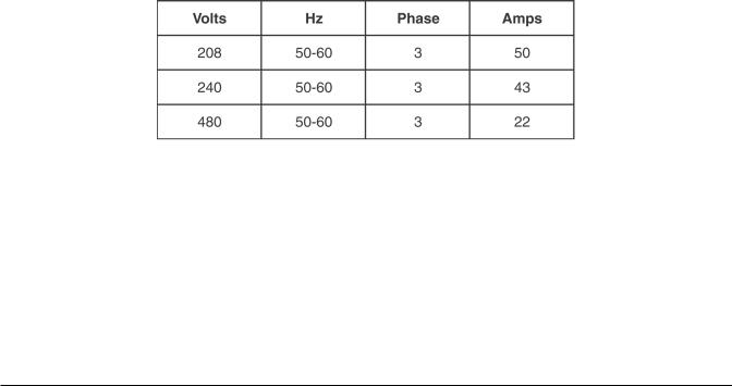
The HO300E is an electrically heated oven consisting of six W-shaped elements, each rated at 3.0 kW for a total input of 18.0 kW. The electrical input is shown in the table below:
Heating Circuit Supply Voltage
Both gas and electric ovens require a dedicated 15-amp, 110 V 50 Hz or 120 V 60 Hz, single-phase supply with ground, connected at the control circuit terminal block located behind the right side service panel. If oven is installed in conjunction with an HPC800 Proofing Cabinet, a separate 120 V supply is required for the proofer.
– 7 –

OPERATION
WARNING: THE MINI-RACK OVEN AND ITS PARTS ARE HOT. USE CARE WHEN OPERATING, SERVICING OR CLEANING THE OVEN.
CONTROLS
– 8 –

Control Guide
Button |
Action |
Display |
|
|
|
POWER |
Press to turn the oven |
Control panel displays are lit when the oven is on. Oven |
|
ON or OFF. |
defaults to Program 0. If oven is turned OFF and back |
|
|
ON within 2 minutes, the oven will come up in the last |
|
|
mode and oven setting. |
|
|
|
AUTO ON/OFF |
Press to enter current time |
The AUTO ON/OFF TIMER window displays the current |
TIMER |
or time for oven to |
time or the time the oven will automatically turn ON or |
|
automatically turn ON or |
OFF. |
|
OFF, when corresponding |
|
|
Auto On Time or Auto Off |
|
|
Time button is pressed. |
|
|
|
|
AUTO ON TIME |
Press arrow keys to set |
The AUTO ON/OFF TIMER window displays the time |
|
the desired time of oven to |
the oven will automatically turn ON. |
|
automatically turn ON. |
|
|
|
|
AUTO OFF TIME |
Press arrow keys to set |
The AUTO ON/OFF TIMER window displays the time |
|
the desired time of oven to |
the oven will automatically turn OFF. |
|
automatically turn OFF. |
|
|
|
|
TIMER ON/OFF |
Press to turn the automatic |
The indicator light beside the timer ON/OFF button is |
|
timer ON or OFF. |
lit when the function is enabled. |
|
|
|
SET TEMP |
Use to enter bake programs. |
The SET TEMP window displays the set temperature. |
|
|
The heat ON light is lit while the oven is heating. The |
|
|
actual temperature in the oven cavity is displayed in the |
|
|
OVEN TEMP window. |
|
|
|
BAKE TIMER |
Press arrow keys to enter |
The BAKE TIMER window displays the amount of time |
|
the BAKE time |
for the current baking cycle. The minutes set are the |
|
(1 minute increments). |
left two digits and minutes remaining are the right two |
|
Press the up arrow key |
digits. The windows can be set to display hours and |
|
to enter additional time |
minutes remaining. The ON light is lit when bake time |
|
at the end of the bake |
is active. |
|
program. |
|
|
|
|
STEAM TIMER |
Press to enter the STEAM |
The STEAM TIMER window displays the amount of |
|
time (5-second increments |
time set for the steam cycle. The ON light is lit when |
|
in Bakery mode; 1-second |
the steam system is active. |
|
increments in Food Service |
|
|
mode). |
|
|
|
|
AIRFLOW |
Press to enter into beginning |
The DELAY TIMER window displays the amount of |
DELAY |
of baking cycle. |
time set for the circulation blower delay cycle |
|
|
0-9 minutes. |
|
|
|
|
Press to start the |
The ON light blinks when the BAKE TIMER is active. |
|
BAKE TIMER. |
|
|
|
|
|
|
|
– 9 –

Control Guide (cont)
Button |
Action |
Display |
|
|
|
|
Press to stop the BAKE |
The ON light is off when the BAKE TIMER is inactive. |
|
TIMER or silence the |
|
|
beeper after the BAKE |
|
|
TIMER has timed out. |
|
|
|
|
PROGRAM |
Press the |
The PROGRAM window displays the number of the |
|
arrow keys to select |
current program. |
|
a bake program. |
|
|
|
|
STEP |
Use to enter bake programs. |
The corresponding indicator light will be lit (1 to 4), |
|
|
depending on which step is selected. |
|
|
|
|
Press to open or |
The indicator light next to the VENT button is lit when |
|
close the vent. |
the vent cycle is enabled. |
|
|
|
|
Use to cool down the oven. |
To enable this feature, set a temperature at least |
|
|
25°F (14°C) cooler than the oven temperature. Press |
|
|
the COOL DOWN button. The COOL DOWN mode is |
|
|
exited when the oven reaches the new set temperature, |
|
|
or if door is opened when temperature is 25°F (14°C) |
|
|
below set temperature, or by pressing any button. |
|
|
|
– 10 –
Auto ON/OFF Timer
Setting Clock
Auto ON/OFF Timer display shows the current time of day. To set the clock, the control must be turned on. Press and hold either of the arrow buttons until the colon between the hours and minutes display stops blinking. Use the up and down arrow buttons to adjust time of day. After 5 seconds of no use, the colon will start to blink again.
The oven can be set to turn itself on and off. After the Auto ON/OFF Timer is set, the POWER ON OFF button can be pressed to turn the oven off. This will not disrupt the AUTO ON/OFF setting. Electrical power to the oven must remain on.
1.To set the oven to turn on, press and hold the AUTO ON TIME button. The previously entered start time will appear in the display. Use the UP and DOWN arrows to adjust the start time. Then release the AUTO ON TIME button.
2.To set the oven to turn off, press and hold the AUTO OFF TIME button. The previously entered end time will appear in the display. Use the UP and DOWN arrows to adjust the end time. Then release the AUTO ON TIME button.
3.To enable the automatic start, press the TIMER ON/OFF button until the indicator LED to the right of the TIMER ON/OFF button is illuminated.
Backup Battery
The clock is backed up by a lithium battery which keeps the clock circuitry operating when all external power is off. If the battery becomes low or dead while the external power is off, the display will read 12:00 (12 hr mode) or 0:00 (24 hr mode) and will not increment until a new time is set. The clock will operate with a dead or missing battery, but must be set each time external power is turned on. Batteries should be replaced when low or dead to avoid corrosive damage to the circuitry.
– 11 –
 Loading...