


 Loading...
MODEL SR24H
MODEL SR24 SERIES DISHWASHERS
MODELS
SR24C ML-130021
SR24H ML-130022
R
701 S. RIDGE AVENUE TROY, OHIO 45374-0001
937 332-3000
www.hobartcorp.com
FORM 35309 Rev. B (Jan. 2006)

TABLE OF CONTENTS
General . . . . . . . . . . . . . . . . . . . . . . . . . . . . . . . . . . . . . . . . . . . . . . . . . . . . 3
Installation . . . . . . . . . . . . . . . . . . . . . . . . . . . . . . . . . . . . . . . . . . . . . . . . . 3
Unpacking . . . . . . . . . . . . . . . . . . . . . . . . . . . . . . . . . . . . . . . . . . . . . . 3
Panel Assembly . . . . . . . . . . . . . . . . . . . . . . . . . . . . . . . . . . . . . . . . . 3
Location. . . . . . . . . . . . . . . . . . . . . . . . . . . . . . . . . . . . . . . . . . . . . . . . 4
Details and Dimensions . . . . . . . . . . . . . . . . . . . . . . . . . . . . . . . . . . . 4
Machine Installation Connections and Details . . . . . . . . . . . . . . . . . 6
Plumbing Connections . . . . . . . . . . . . . . . . . . . . . . . . . . . . . . . . . . . . 7
Water Supply . . . . . . . . . . . . . . . . . . . . . . . . . . . . . . . . . . . . . . . . 7
Water Requirements . . . . . . . . . . . . . . . . . . . . . . . . . . . . . . . . . . 7
Drain . . . . . . . . . . . . . . . . . . . . . . . . . . . . . . . . . . . . . . . . . . . . . . 7
Electrical Connections . . . . . . . . . . . . . . . . . . . . . . . . . . . . . . . . . . . . 8
Electrical Connection (Model SR24H) . . . . . . . . . . . . . . . . . . . . 8
Electrical Connection (Model SR24C. . . . . . . . . . . . . . . . . . . . . 8
Chemical Sanitizer (Model SR24C Only) . . . . . . . . . . . . . . . . . . . . . 8
Initial Filling (Model SR24H Only) . . . . . . . . . . . . . . . . . . . . . . . . . . . 9
Priming the Booster . . . . . . . . . . . . . . . . . . . . . . . . . . . . . . . . . . 9
Booster Heater (Model SR24 Only) . . . . . . . . . . . . . . . . . . . . . . 9
Fill . . . . . . . . . . . . . . . . . . . . . . . . . . . . . . . . . . . . . . . . . . . . . . . . . . . . 9
Operation . . . . . . . . . . . . . . . . . . . . . . . . . . . . . . . . . . . . . . . . . . . . . . . . 10 Preparation . . . . . . . . . . . . . . . . . . . . . . . . . . . . . . . . . . . . . . . . . . . 10 Controls . . . . . . . . . . . . . . . . . . . . . . . . . . . . . . . . . . . . . . . . . . . . . . 10 Dishwashing . . . . . . . . . . . . . . . . . . . . . . . . . . . . . . . . . . . . . . . . . . 10 Chemical Dispensing Pumps . . . . . . . . . . . . . . . . . . . . . . . . . . . . . 11 DOs and DON'Ts for Your New Hobart Warewasher . . . . . . . . . . 11
Cleaning . . . . . . . . . . . . . . . . . . . . . . . . . . . . . . . . . . . . . . . . . . . . . . . . . 12
Maintenance . . . . . . . . . . . . . . . . . . . . . . . . . . . . . . . . . . . . . . . . . . . . . . 13
Deliming . . . . . . . . . . . . . . . . . . . . . . . . . . . . . . . . . . . . . . . . . . . . . 13
Deliming Model SR24C (Chemical Sanitizing Model) . . . . . . . . . 13
Deliming Model SR24H (Hot Water Sanitizing Model) . . . . . . . . . 14
Lubrication . . . . . . . . . . . . . . . . . . . . . . . . . . . . . . . . . . . . . . . . . . . 14
Troubleshooting . . . . . . . . . . . . . . . . . . . . . . . . . . . . . . . . . . . . . . . . . . . 15
Chemical Sensing Module — Operation and Start-Up . . . . . . . . . 16
Chemical Sensing Module — To Recalibrate Sensors . . . . . . . . 16
Chemical Sensing Module — Troubleshooting. . . . . . . . . . . . . . . 16
© HOBART CORPORATION, 2006 |
– 2 – |

Installation, Operation and Care of
MODEL SR24 SERIES DISHWASHERS
SAVE THESE INSTRUCTIONS
GENERAL
The SR24 Series Dishwashers are fully automatic, front-loading machines that are equipped with a 1/2 H.P. electric motor.
Standard equipment includes two standard 20" x 20" racks, dial thermometers for both rinse and wash cycles, synchronous timer, pilot light and lower front trim panel. An over temperature light is standard on model SR24H only. Side and top panel kits are available should a free-standing model be desired.
The model SR24H features a built-in booster heater, while the SR24C is a low-temperature, chemical-sanitizing model for use with 6.0% sodium hypochlorite solution (bleach) as a sanitizing agent. If 8.4% bleach is to be used, contact Hobart service to change the sanitizer pump settings (charges will apply).
A chemical sensing module is an available option; it indicates when chemical supplies must be replenished.
Chemical dispensing pump(s), up to three, are available options at time of order.
INSTALLATION
UNPACKING
Immediately after unpacking the dishwasher, check for possible shipping damage. If this machine is found to be damaged after unpacking, save the packaging material and contact the carrier within 15 days of delivery.
PANEL ASSEMBLY
If optional panel kits are to be installed, they must be installed before positioning the dishwasher. Refer to installation instructions (F-33163) supplied with panel kit.
– 3 –
LOCATION
Prior to installation, test the electrical service to make sure that it agrees with the specifications on the machine data plate, located on the top of the door.
Place the machine in its operating location. Before any connections are made, the machine must be level. Use the tank seam at the top of the sump inside the tank as a reference. To level the machine, pour enough water in the tank to reach the seam and then thread the adjustable feet in or out until the water level is even with the seam.
The lower front panel must be removed to accommodate plumbing and electrical connections.
Remove the two screws that secure the lower front panel and the kick panel. Remove both panels.
Replace these panels after installation.
Machines without side and top panels should be anchored to the counter under which they are installed by assembling two screws (not supplied) through the holes in the top of the tank.
The machine must be cleaned after installation and before being put into service. Refer to the OPERATION section for detailed instructions.
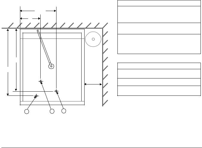
DETAILS AND DIMENSIONS |
||
|
143/8" |
|
|
7" |
|
WALL |
|
|
183/4" |
|
|
201/2" |
|
|
|
|
9" Min. |
|
|
Req'd |
|
|
for |
|
|
SR24C |
|
|
Only |
P1 |
P2 |
E1 |
LEGEND
P1 Single fill and rinse pipe connection, 3/4" female garden hose fitting on 6' long hose supplied with the machine; 110°F water min. for SR24H; 120°F water min. for SR24C.
P2 Drain pipe connection, 3/4" MPT fitting with
10' hose supplied with the machine.
E1 Location of electrical connection, SR24H only:
3/4" elec. connector (11/8" dia. hole), 4" AFF. Location of electrical connection, SR24C only: cord and plug supplied.
INTERIOR DIMENSIONS
1.Maximum inside height from inside rack to top wash arm is 165/8".
2.Width is 223/16".
3.Front to rear is 211/2" with door closed.
NOTE: Certain materials, including silver plate, aluminum and pewter are attacked by sodium hypochlorite (bleach). Refer to DOs AND DON'Ts FOR YOUR NEW HOBART WAREWASHER.
SR24C |
Net Weight of Machine: |
135 lbs. |
SR24C |
Domestic Shipping Weight: |
155 lbs. |
SR24H |
Net Weight of Machine: |
146 lbs. |
SR24H |
Domestic Shipping Weight: |
166 lbs. |
– 4 –

|
|
Minimum |
Maximum |
|
|
|
|
Machine Type & |
Rated |
Supply CKT |
Overcurrent |
|
|
|
|
Specification |
AMPS |
Conductor |
Protective |
|
|
|
|
|
|
Ampacity |
Device |
|
|
|
|
|
|
|
|
|
|
|
|
SR24C 120/60/1 |
9 |
15 |
15 |
|
|
|
|
|
|
|
|
|
|
|
|
SR24H 120/240 (3W)/60/1 |
37.6 |
50 |
50 * |
|
|
|
|
or 120/208 (3W)/60/1 |
42.0 |
50 |
50 * |
|
237/8" |
|
|
|
|
||||||
* These are 3-wire systems that require (3) #8 AWG copper |
|
|
|||||
wires (90°C) including a current carrying neutral. In addition, |
|
|
|
|
|||
|
|
|
|
||||
a fourth wire must be provided for machine ground. Do not |
|
|
|
|
|||
|
|
|
|
||||
|
|
|
|
||||
connect these machines to a 120 VAC circuit. |
|
|
|
|
|
||
|
|
|
|
|
|||
|
|
|
|
|
|
|
|
Recommended rough-in drain location 11/2" trade size pipe minimum, reduced down to 3/4" FPT connector (by customer).
|
Recommended water service rough-in, |
|
||
Recommended |
1/2" trade size pipe minimum, with |
|
||
|
||||
shut-off valve and 3/4" male garden |
|
|||
17" or less |
hose fitting (by customer). |
|
||
|
|
|
||
|
Floor Line |
|
|
|
|
|
|
|
|
Overall
Height
Without
Top Panel 345/8" min. 355/8" max.
NOTE: If drain hose is looped above a sink, the |
|
3/4" |
P2 |
|
|||
|
|
223/8" |
|
loop must not exceed 38" above finished floor. |
|
|
|
|
P1 |
E1 |
|
|
|
421/2"
24"
165/8" Max. Load Height
WALL
14"
15" 41/8"
– 5 –
Loading...