


DE1

I
N
S
T
R
U
D SERIES
REACH-IN
REFRIGERATORS & FREEZERS
C
T
I
REACH-INS
O
D SERIES
N
S
701 S. RIDGE AVENUE
TROY, OHIO 45374-0001
937 332-3000
www.hobartcorp.com
FORM 18261 Rev. E (Jan. 2002)
Installation, Operation and Care of
D SERIES REACH-IN REFRIGERATORS & FREEZERS
SAVE THESE INSTRUCTIONS
GENERAL
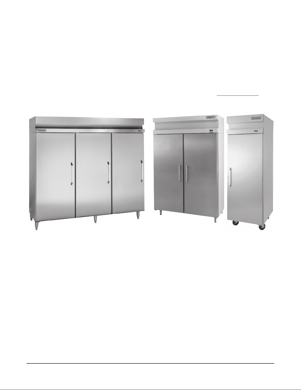
D Series Reach-In Refrigerators (38°F) and Freezers (0°F) may be ordered as one-, two-, or threesection cabinets. Doors may be full height or half height solid with stainless exterior surface and ABS
plastic interior surface. Glass doors, full height or half height, are available for
Capacity refrigeration systems are included with glass door units. Legs or 5" casters are available. The
exterior sides and the interior of the D Series cabinet are DuraFinish
TM
aluminum.
refrigerators only. High
D Series Reach-In Refrigerators & Freezers
INSTALLATION
UNPACKING
Immediately after unpacking the reach-in, check for possible shipping damage. If this unit is found to
be damaged after unpacking, save the packaging material and contact the carrier within 15 days of
delivery.
Prior to installation, test the electrical service to assure that it agrees with the specifications on the
machine data plate located on the upper left side wall inside the cabinet.
LOCATION
For optimum performance, the condensing unit of the reach-in must have an adequate supply of air for
cooling purposes. The operating location must provide either a minimum 12
condensing unit or the unrestricted flow of air at the back of the reach-in.
© HOBART CORPORATION, 1991
–2–
"
clearance overhead of the
ASSEMBLY
Some components can be removed to allow the cabinet to pass through short or narrow doorways.
The door handle can be removed as follows:
1. If the adhesive-backed trim pieces are damaged during removal, new ones can be purchased
from Hobart. The adhesive-backed trim pieces on the top and bottom of the handles need to be
peeled off to expose the screws.
2. Peel off the trim pieces and remove the
FRONT TRIM PANEL
UPPER
HINGE
screws which secure the handles.
3. Reinstall screws, handles and trim
pieces in reverse order of disassembly.
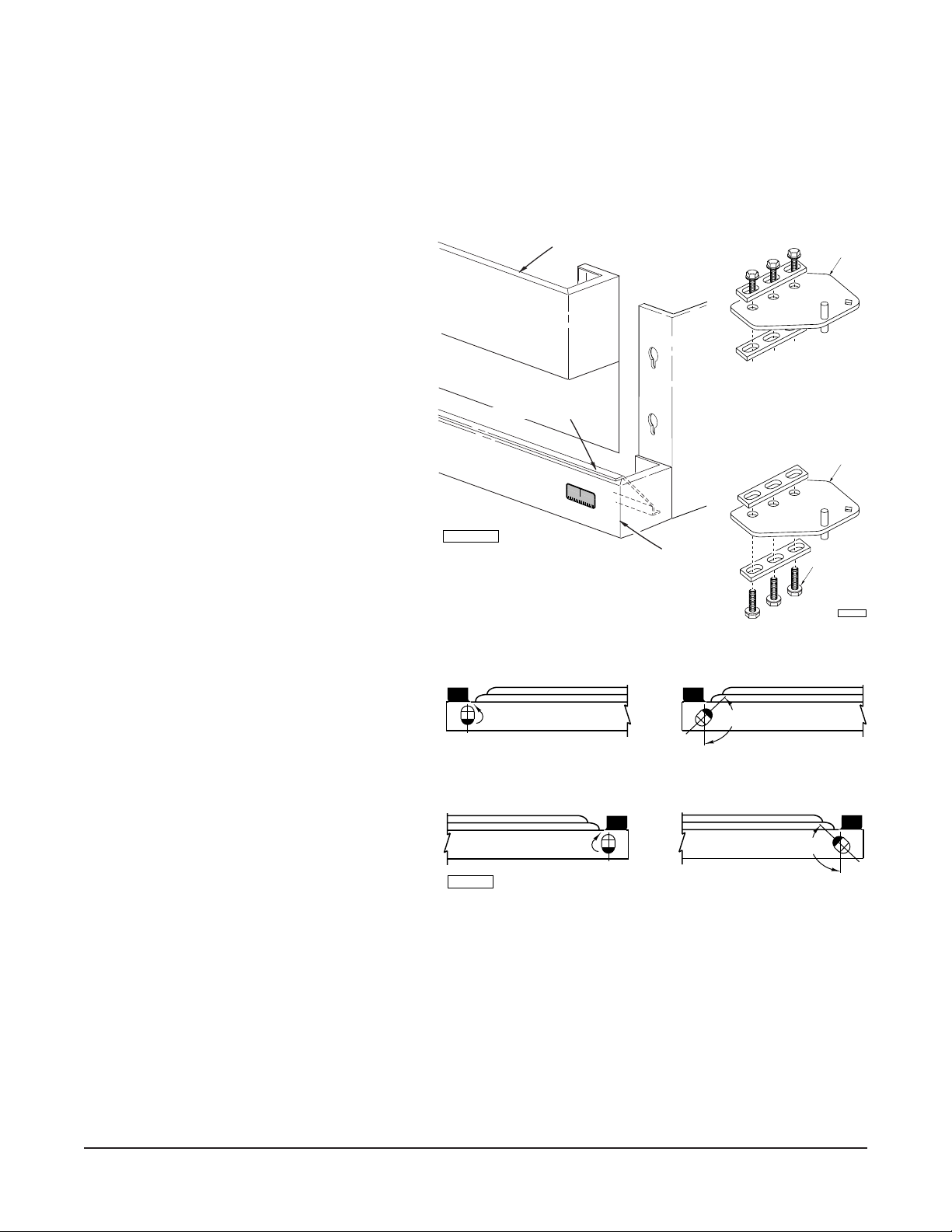
Door(s) and hinges can be removed as
follows:
1. Lift up and remove the front trim panel
(Fig. 1).
TRIM RAIL COVER
2. Remove the screws which secure the
trim rail cover (Fig. 1), unplug the door
LOWER
HINGE
switch lead wires, and remove the
screws which secure the trim rail (Fig.
1). Carefully lay the trim rail on top of
the cabinet — avoid damaging or
kinking the thermometer capillary tube.
3. Remove the three screws which
secure the upper hinge plate to the
cabinet (Fig. 2). This will remove hinge
tension. Remove the nut underneath
PL-56149
Fig. 1
TRIM RAIL
Fig. 2
SCREWS
(3)
PL-53617
the lower hinge plate which secures
the bottom hinge. Remove door.
UNCOCKED POSITION
COCKED POSITION
Remove lower hinge plate (Fig. 2).
4. If the hinge mechanism should become
uncocked while changing the door, it
will be necessary to recock the hinge
TURN 135º
– POSITION 1 – (LEFT-HAND HINGED DOOR)
135º
mechanism. To do this, remove the
door from the cabinet and position the
UNCOCKED POSITION COCKED POSITION
door face down on a workbench or
table. Using a
5
/16" open end or
TURN 135º
135º
adjustable wrench, turn the hinge
mechanism shaft 135° (Fig. 3).
5. Replace the hinge plates and door(s)
in the reverse order of disassembly.
PL-50961
– POSITION 2 – (RIGHT-HAND HINGED DOOR)
POSITION DOOR IN ONE OF THE TWO POSITIONS SHOWN.
Fig. 3
If cabinets are too tall, the refrigeration system may need to be removed in order to pass through short
openings. Contact your dealer or authorized servicer if this becomes necessary.
Once the cabinet is in its final position, replace any components that may have been removed (door
handle, etc.) and then level the cabinet front-to-back and side-to-side by adjusting the legs as required.
Door Hinging
Should the doors need to be rehinged (from right to left or vice versa) contact a Hobart-authorized
Refrigeration Service Company.
–3–
LEGS OR CASTERS
WARNING: THE CABINET MUST BE BLOCKED AND
STABLE BEFORE INSTALLING LEGS OR CASTERS.
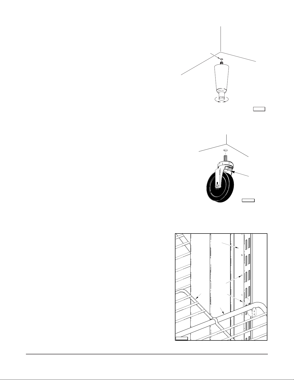
Legs (Fig. 4)
To install the legs, raise and block the reach-in a minimum of
7" from the floor and thread the legs into the threaded holes on
the bottom of the cabinet. The unit must be level in order to
operate properly. Turn the adjustable feet in or out as required
to level the unit front-to-back and side-to-side.
NOTE: Three-section front opening cabinets come with five
legs; the fifth leg should be placed in the front center threaded
hole. Failure to install these legs in the proper location may
result in damage to the cabinet.
Casters (Fig. 5)
Use casters only on reach-in models that have cord and plug
electrical connections.
Raise and block the cabinet a minimum of 7" from the floor.
Thread the casters into the holes in the bottom of the cabinet
(Fig. 6). Casters with brake should be installed at the front.
Securely tighten the caster with the octagon shaped bolt head
underneath — not the round flange on top.
THREADED HOLE
RAISE
LOWER
PL-56125
Fig. 4
BOLT
Shelves (Fig. 6)
If purchased, the shelves and shelf clips are shipped with
the cabinet. Insert the shelf clips into the pilaster and
install the shelves. Index holes are provided in the pilaster
to help in leveling the shelves.
Bonus shelves are provided to fill the space between the
shelves. These are positioned and supported by the
shelves.
NOTE: Loosen all thumbscrews which secure shelf
pilasters and light cover(s) prior to placing product in the
cabinet. Thumbscrews should be loose enough to remove
with your fingers so parts can be readily removed for
cleaning without the use of tools. Failure to comply with
this request will invalidate the NSF listing.
Compressor Mounts
Some reach-in refrigeration models have the compressor
specially mounted to help prevent damage during
shipment. If the compressor is mounted on shipping
blocks, remove the shipping blocks before operating the
compressor. If the compressor is mounted on springs,
refer to the tag attached to the compressor.
PL-50910
COLD AIR
DUCT
BONUS
SHELF
Fig. 5
PILASTER
INDEX
HOLE
SHELF
CLIP
SHELF
Fig. 6
PL-53353
– 4 –
 Loading...