


 Loading...
Hobart CE6HD, CE10HD, ML-138011, CE10FD, CE20HD User Manual
...ELECTRIC COMBI,
CONVECTION & STEAM OVENS
BOILERLESS
(LEFT HINGED DOOR)
CE6HD ML-138010
CE10HD ML-138012
CE10FD ML-138016
CE20HD ML-138014
CE20FD ML-138018
(RIGHT HINGED DOOR)
CE6HD ML-138011
CE10HD ML-138013
CE10FD ML-138017
CE20HD ML-138015
CE20FD ML-138019
701 S. RIDGE AVENUE TROY, OHIO 45374-0001
937 332-3000
www.hobartcorp.com
FORM 35474 (July 2007)

TABLE OF CONTENTS |
|
GENERAL .............................................................................................................................................................. |
3 |
INSTALLATION ...................................................................................................................................................... |
3 |
Unpacking ........................................................................................................................................................ |
3 |
Installation Codes and Standards .................................................................................................................... |
3 |
Location ........................................................................................................................................................... |
4 |
Door Opening................................................................................................................................................... |
4 |
Stacking Kits .................................................................................................................................................... |
4 |
Leveling............................................................................................................................................................ |
4 |
Water Requirements ........................................................................................................................................ |
4 |
Plumbing Connections ..................................................................................................................................... |
4 |
Water Supply Connections............................................................................................................................... |
4 |
Drain Connection ............................................................................................................................................. |
5 |
Electrical Connection ....................................................................................................................................... |
5 |
Vent Hood ........................................................................................................................................................ |
5 |
Before First Use ............................................................................................................................................... |
5 |
OPERATION........................................................................................................................................................... |
6 |
Door Switch...................................................................................................................................................... |
6 |
Door Opening and Closing............................................................................................................................... |
6 |
Loading the Oven............................................................................................................................................. |
6 |
Unloading the Oven ......................................................................................................................................... |
7 |
Cooking Modes ................................................................................................................................................ |
7 |
Control Panel ................................................................................................................................................... |
7 |
Initial Start-up................................................................................................................................................. |
10 |
Setting the Internal Clock............................................................................................................................... |
10 |
Setting the Temperature................................................................................................................................. |
10 |
Setting the Timer............................................................................................................................................ |
11 |
Setting the Humidity....................................................................................................................................... |
11 |
Setting the Vent Position................................................................................................................................ |
11 |
Setting the Fan Speed ................................................................................................................................... |
12 |
Fast Cool Down ............................................................................................................................................. |
12 |
Selecting the Cooking Mode .......................................................................................................................... |
13 |
Preheating the Oven ...................................................................................................................................... |
13 |
Using Convection Mode................................................................................................................................. |
13 |
Using Steam Mode ........................................................................................................................................ |
14 |
Using Combi Mode ........................................................................................................................................ |
14 |
Temperature Probe ........................................................................................................................................ |
15 |
Using the Product Temperature Probe........................................................................................................... |
16 |
Writing a Cooking Phase................................................................................................................................ |
17 |
Erasing a Cooking Phase .............................................................................................................................. |
17 |
Writing a Cooking Program............................................................................................................................ |
18 |
Modifying a Cooking Program........................................................................................................................ |
19 |
Reviewing a Cooking Program ...................................................................................................................... |
19 |
Erasing a Cooking Program........................................................................................................................... |
19 |
Using a Cooking Program.............................................................................................................................. |
20 |
Setting a Preheat Program ............................................................................................................................ |
20 |
MAINTENANCE ................................................................................................................................................... |
21 |
Service Adjustments ...................................................................................................................................... |
21 |
Shutting Down the Oven ................................................................................................................................ |
21 |
CLEANING ........................................................................................................................................................... |
21 |
TROUBLESHOOTING ............................................................................................................... |
..........................23 |
Autodiagnostics.............................................................................................................................................. |
23 |
Service and Parts Information........................................................................................................................ |
23 |
Service Parameter Setup............................................................................................................................... |
24 |
©HOBART, 2007 |
– 2 – |

INSTALLATION, OPERATION AND CARE OF ELECTRIC COMBI, CONVECTION & STEAM OVENS
SAVE THESE INSTRUCTIONS
GENERAL
The Electric Combi, Convection & Steam Ovens are single compartment ovens that provide convection heating and/or steaming in the cooking chamber.
The Hobart Combi Electric ovens are sized 6, 10, or 20 levels high. The 6 level ovens are Half depth only. The 10 and 20 level ovens are either Full or Half depth. All models include a Digital programmable control. The bold numbers and letters explain the model-number conventions.
The 6 or 10 level ovens can be installed on a suitable countertop using the 2" legs (standard) or the optional 6" legs. The 6 or 10 level ovens can also be installed on an accessory stand. The accessory stand may be equipped with an accessory Pan Slide which provides rack or pan storage underneath the oven. On 6 or 10 level ovens, the accessory Landing Table can load or unload all racks in one motion when the oven is mounted on the accessory stand. Additional racks are also available accessories. The 20 level ovens are installed with legs and come with a Trolley to allow loading or unloading all racks in one motion. An optional Hose Spray accessory supplied by others can be installed near the oven to facilitate easy cleaning of the accessory racks.
INSTALLATION
UNPACKING
Immediately after unpacking the oven, check for possible shipping damage. If the oven is found to be damaged, save the packaging material and contact the carrier within 15 days of delivery.
Prior to installation, verify that the electrical and water service agrees with the specifications on the oven data plate and in this manual.
INSTALLATION CODES AND STANDARDS
In the United States, the Hobart Combi Oven must be installed in accordance with:
1.State and local codes.
2.National Electrical Code (ANSI/NFPANo.70, latest edition) available from the National Fire Protection Association, Batterymarch Park, Quincy, MA 02269.
3.Vapor Removal from Cooking Equipment, (NFPA-96, latest edition) available from NFPA.
In Canada, the Hobart Combi Oven must be installed in accordance with:
1.Local codes.
2.Canadian Electrical Code (CSA C22.2 No.3, latest edition) available from the Canadian Standards Association, 5060 Spectrum Way, Mississauga, Ontario, Canada L4W 5N6.
–3 –

LOCATION
Allow space for operating the oven. Do not obstruct the ventilation ports above the oven. To provide ventilation access, allow 1" clearance on the left side of the oven and 21/2" clearance at the rear. A suitable amount of space (18" minimum) should be provided on the right side of the machine for operation, cleaning and service.
DOOR OPENING
The standard oven is delivered with the door hinged on the left. If the door opening needs to be changed, contact your authorized Hobart Service office.
STACKING KITS
Stacking kits are available to allow ovens to stack, one on top of the other (available for 6 and 10 level ovens only). The bottom oven must be the same depth as the upper oven. Assembly Instructions are included with the kit.
LEVELING
Use a spirit level on a rack in the oven to make sure the oven is level, both front-to-back and side-to-side. On 20 levels, accessory stands, and optional 6" legs, adjust the leveling feet on the bottom of the legs by turning the feet in or out to level the oven. After the drain is connected, check for level by pouring water onto the floor of the compartment. All water should drain through the drain opening.
WATER REQUIREMENTS
 As with all steam related products, water filtration and regular filter replacements coupled with routine deliming are required. Your local Hobart Service office can recommend a water treatment system to meet the needs of your local water conditions. Contact your local Hobart Service representative for water treatment offerings.
Proper water quality can improve the taste of the food prepared in the oven, reduce liming and extend equipment life. Local water conditions vary from one location to another. The recommended proper water treatmentforeffectiveandefficientuseofthisequipmentwillalsovarydependingonthelocalwaterconditions. Ask your municipal water supplier for details about your local water supply prior to installation.
Recommended water hardness is less than 5.0 grains of hardness per gallon with pH from 7.0 to 8.0. Chlorides must not exceed 30 parts per million. Water hardness above 6.0 grains per gallon should be treated by a water conditioner (water softener and/or in-line water treatment). Water hardness below 4.0 grains per gallon may also require a water treatment system to reduce potential corrosion. Water treatment has been shown to reduce costs associated with machine cleaning, reduce deliming and reduce corrosion of metallic surfaces.
PLUMBING CONNECTIONS
 Plumbing connections must comply with applicable sanitary, safety and plumbing codes.
WATER SUPPLY CONNECTIONS
Connect treated potable water (cold) to the inlet. Untreated water contains scale producing minerals which, if supplied, can precipitate and adhere to the surfaces inside the oven. This can result in early component failure and reduced product life.
– 4 –

DRAIN CONNECTION
 In order to avoid any back pressure in the oven, do not connect solidly to any drain.
Extend the drain line from the 1" NPT drain pipe extending from the bottom of the oven at the rear to an open gap-type drain. Drain piping must have suitable pitch, have appropriate support along its length, and have no connection to other piping. The material used in the drain line should be heat resistant to at least 212°F (100°C).
ELECTRICAL CONNECTION
 Electrical and grounding connections must comply with the applicable portions of the National Electrical Code and/or other local electrical codes.
 Disconnect electrical power supply and follow lockout / tagout procedures.
The wiring diagram is located on the inside surface of the right side panel as you face the oven. Use copper wire rated for at least 194°F (90°C) for the connection.
Model |
Volts |
Hertz |
Phase |
Amps |
|
208 |
|
|
25 |
CE6HD |
240 |
60 |
3 |
22 |
|
480 |
|
|
11 |
|
208 |
|
|
50 |
CE10HD |
240 |
60 |
3 |
44 |
|
480 |
|
|
22 |
|
208 |
|
|
66 |
CE10FD |
240 |
60 |
3 |
58 |
|
480 |
|
|
29 |
|
208 |
|
|
100 |
CE20HD |
240 |
60 |
3 |
87 |
|
480 |
|
|
44 |
|
208 |
|
|
117 |
CE20FD |
240 |
60 |
3 |
101 |
|
480 |
|
|
58 |
NOTE: Single-phase blower motors are used on these ovens so there is no need to check direction of motor rotation. The fan will rotate in the proper direction.
VENT HOOD
Some local codes may require the Combi oven to be located under an exhaust hood. Information on the construction and installation of ventilating hoods may be obtained from Vapor Removal from Cooking Equipment, NFPA Standard No. 96 (latest edition).
BEFORE FIRST USE
Before using the oven for the first time, it must be "burned in" to release any odors that might result from heating the new surfaces in the oven. Operate the oven at 482°F for 45 minutes in Convection Mode.
– 5 –
OPERATION
 The oven and its parts are hot. Use care when operating, cleaning or servicing the oven. The cooking compartment contains live steam. Stay clear when opening door.
DOOR SWITCH
The oven is equipped with a feature that shuts off power to the oven cavity when the door is opened. The oven will resume cooking once the door is closed.
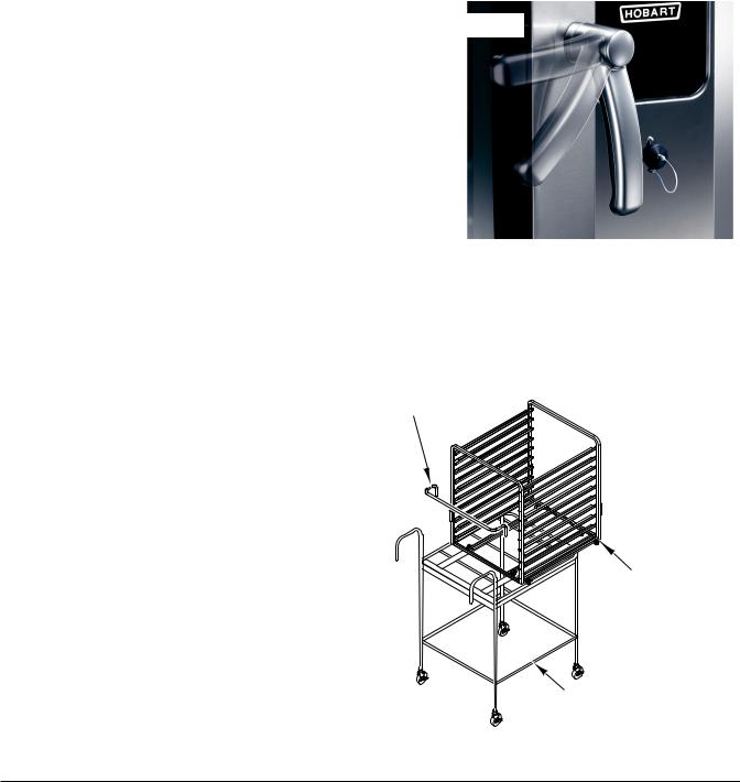
DOOR OPENING AND CLOSING
To open the door (Fig. 1), turn the handle to the horizontal position. Allow a few seconds for steam to escape before pulling the door open.
To close the door (Fig. 1), position handle in the horizontal position and push the door closed. Rotate handle to the vertical position to secure door.
LOADING THE OVEN Loading 6 or 10 Level Ovens
Placetheproducttobecookedinsuitablecontainers. Open the door and slide into the rack guides or place the containers securely on racks in the oven. Close the door.
Loading 6 or 10 Level Ovens With Landing Table And Removable Insert
Place removable insert on the landing table. Place the product to be cooked in suitable containers and slide into the rack guides or place the containers securely on racks on the removable insert (Fig. 2). Place the handle into the removable insert. Open the door. Position the landing table directly in front of the open oven cavity. While holding the landing table in position with one hand, with the other hand, release the insert and gently roll the removable insert into the oven cavity. Make sure that the landing table does not separate from the oven during the transfer. Remove the handle from the insert and close the door.
Loading 20 Level Ovens
Place the product to be cooked in suitable containers and slide into the rack guides or place the containers securely on racks on the trolley (Fig. 3). Place the handle into the trolley. Open the door. Line up the trolley with the trolley slots on the oven and push the trolley into the oven cavity. Remove the handle from the trolley and close the door.
OPEN POSITION
CLOSED POSITION
Fig. 1
HANDLE
REMOVABLE
INSERT
LANDING
TABLE
Fig. 2
– 6 –

UNLOADING THE OVEN Unloading 6 or 10 Level Ovens
Open door partially to allow hot air and steam to escape. Remove the product from the rack guides or racks in the oven. Close the door.
Unloading 6 or 10 Level Ovens With Landing Table And Removable Insert
Open door partially to allow hot air and steam to escape. Position the landing table (Fig. 2) directly in front of the oven cavity. Insert the handle into the removable insert. Using protective gear, carefully roll the removable insert onto the landing table. Make sure that the landing table does not separate from the oven during transfer. Close the door.
Unloading 20 Level Ovens
Open door partially to allow hot air and steam to escape. Insert the handle into the trolley. Using protective gear, pull the trolley (Fig. 3) out of the oven. Close the door.
COOKING MODES
There are three modes of cooking available with the Combi Oven.
Convection Mode
Convection Baking involves baking, browning, roasting, etc. without adding steam or moisture to the process. Hot air is circulated to maintain even temperatures throughout the oven.
Steam Mode
Steam cooking is used for stewing, poaching, and gentle cooking of products cooking in water. Steam flows without pressure into the oven. The fan circulates the steam to all parts of the oven.
Combi Mode
Combi baking/steaming is used for baking, roasting, or braising when steam needs to be added to the oven during a convection baking operation.
CONTROL PANEL
The control panel (Fig. 4) has a screen that displays to the user the functions in progress. All features are displayed on the screen and adjusted by using the buttons on the control panel.
HANDLE
TROLLEY
Fig. 3
Fig. 4
– 7 –
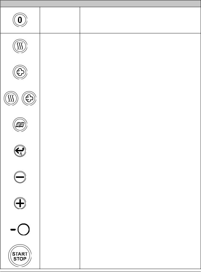
CONTROL PANEL BUTTONS
ON/OFF Button |
Press this button to turn the oven on or off. |
|
|
|
|
Convection Mode |
Press this button to set the oven to Convection Mode. The |
|
|
|
|
button will illuminate to indicate it has been selected. |
|
|
|
|
|
|
|
|
|
|
|
|
|
|
|
|
|
Steam Mode |
Press this button to set the oven to Steam Mode. The button |
|
|
|
|
will illuminate to indicate it has been selected. |
|
|
|
|
|
|
|
|
|
|
|
|
|
|
|
|
|
Combi Mode |
Press both buttons to set the oven to Combi Mode. The but- |
|
|
|
|
tons will illuminate to indicate they have been selected. |
|
|
|
|
|
|
|
|
|
|
|
|
|
|
|
|
|
Program Button |
Press this button to use an existing program or to write a |
|
|
|
|
new program. (Press and hold 3 seconds to name program) |
|
|
|
|
|
|
|
|
|
|
|
|
|
|
|
|
|
Enter Button |
Press this button to confirm a program selection. When used |
|
|
|
|
(also used as |
|
|
|
|
|
during Convection Mode, humidity will be injected into the |
|
|
|
|
|
Humidity Injector |
|
|
|
|
|
oven cavity. (Press and hold 3 seconds to save recipe) |
|
|
|
|
|
Button) |
|
|
|
|
|
|
|
|
|
|
|
|
|
|
|
|
|
Minus Button |
Press this button to decrease setting feature such as tem- |
|
|
|
|
perature or time. |
|
|
|
|
|
|
|
|
|
|
|
|
|
|
|
|
|
Plus Button |
Press this button to increase setting feature such as tem- |
|
|
|
|
perature or time. |
|
|
|
|
|
|
|
|
|
|
|
|
|
|
|
|
|
Selection Line |
Press these buttons to select the feature displayed in the |
|
|
|
|
Button |
control panel next to each Selection Line. These features will |
|
|
|
|
(total of five) |
change depending on the screen being displayed. |
|
|
|
|
|
|
|
|
|
|
START/STOP |
Press this button to start or stop a program or cooking cycle. |
|
|
|
|
Button |
(Press and hold 3 seconds for preheat) |
– 8 –
Loading...