


 Loading...
6801 MEAT SAW TECHNICAL MANUAL (208-230/60/3)
SPECIFICATION SHEET INSTALLATION INSTRUCTIONS OPERATION INSTRUCTIONS CLEANING INSTRUCTIONS MAINTENANCE INSTRUCTIONS TROUBLE SHOOTING INSTRUCTIONS WIRING DIAGRAMS
CATALOG OF REPLACEMENT PARTS SMARTPARTS™ USER GUIDE RECOMMENDED SPARE PARTS LIST

Need other Hobart Services?
•Warranty Registration
•Delivery and Installation
•Preventive Maintenance
•Hobart Service Contracts
•Extended Warranty Contracts
•Parts and Accessories
•Specialty Programs
•Water Treatment Programs
6801 Meat Saw Technical Manual Page 2 of 51
Item # ________________________________
Quantity _______________________________
C.S.I. Section 11400
|
|
|
|
|
|
|
|
6801 SERIES |
|
|
701 S Ridge Avenue,Troy, OH 45374 |
|
MEAT SAW |
|
|
1-888-4HOBART • www.hobartcorp.com |
|
|
|
|
|
|
|
|
|
|
|
|
|
|
|
|
|
|
|
|
|
|
|
|
|
|
|
|
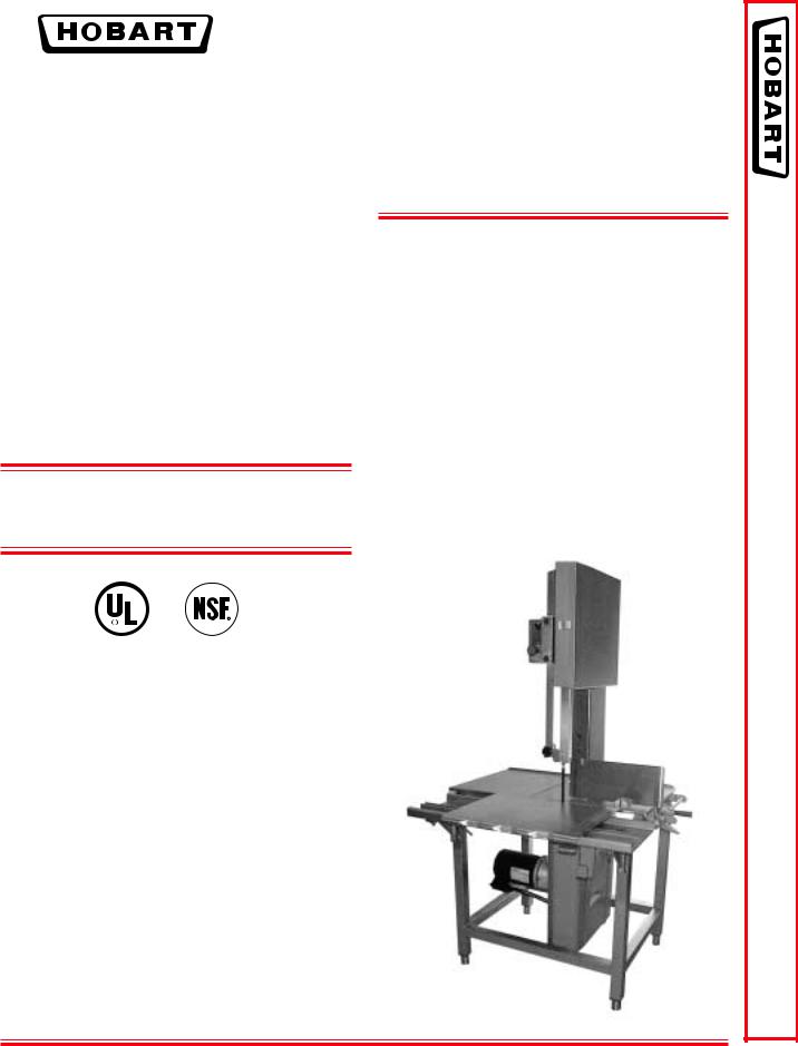
STANDARD FEATURES |
MODEL |
■ 3 H.P. Motor |
6801 Series – Vertical Meat Saw |
|
|
■ Direct Gear Drive Transmission |
Specifications, Details and Dimensions on Inside and Back. |
■Tri-Rail Carriage
■Open Frame Stainless Steel Construction
■Center Crown Pulley
■Removable Double Flanged Pulleys
■Split Rear Table
■Direction Grain Stainless Steel
■Pivoted Automatic Tension
■Adjustable Legs
■Stainless Steel Top Cover
OPTIONS
Maximum Security Prison Package
R
SERIES 6801 SAW MEAT
F-39903 – 6801 Series Meat Saw |
Page 1 of 4 |
6801 Meat Saw Technical Manual Page 3 of 51
6801 SERIES MEAT SAW
701 S Ridge Avenue,Troy, OH 45374
1-888-4HOBART • www.hobartcorp.com
Page 2 of 4 |
6801 Meat Saw Technical Manual Page 4 of 51 F-39903 – 6801 Series Meat Saw |

701 S Ridge Avenue,Troy, OH 45374
1-888-4HOBART • www.hobartcorp.com
6801 SERIES MEAT SAW
F-39903 – 6801 Series Meat Saw 6801 Meat Saw Technical Manual Page 5 of 51 |
Page 3 of 4 |

6801 SERIES MEAT SAW
701 S Ridge Avenue,Troy, OH 45374
1-888-4HOBART • www.hobartcorp.com
SOLUTIONS / BENEFITS
3 H.P. Motor
Durability and reliability
■Totally enclosed
■Flange mounted with grease-packed ball bearings
■Water resistant
Direct Gear Drive Transmission
Performance
■No belts to replace, slip, adjust or break
■Helical gear reduction
■Blade speed; 4150 fpm
Safety Features
Safety
■Upper and lower pulleys are completely enclosed
■Accessible blade is guarded above and below the cutting zone
■Pusher plate provided to eliminate handling items too close to blade
Cleanability
Labor savings, improved sanitation
■Total open construction and complete hose down capabilities
■Lower “lift-out” guide assembly has stainless steel blade guide
■Built-in tungsten carbide blade back-up block assembly is removable
■Enclosed bone dust system, with large lower scrap pan, keeps dust where it belongs
■No tools needed for part removal, including both pulleys, blade cleaners and guide assemblies
■Exclusive two-piece table and open frame design make sink washing or high pressure hose-down a cinch
Pivoted Automatic Tension
Productivity, ease of use
■Entire motor, transmission and lower pulley assembly is pivot mounted
■Blade tension control accessible just below right table
■Simple adjustment allows for broad blade length tolerance
User Friendly Controls
Ease of use
■Single pull-to-start, push-to-stop switch
■Heater provided with each control to prevent moisture condensation on electrical components
Integrated Pulley Design
Durability, reliability
■Bright tinned cast iron upper and lower blade pulleys are easily removed
■True-running of the blade is assured by precision pulley balance
■Blade retaining double flanges and center crown give long life without loss of blade integrity
Movable Carriage Tray
Convenience, labor savings
■16" D x 241⁄4" W
■Stainless steel, turned down edges provide reinforcements for rigidity
■Stepped front edge makes movement of carriage fast and easy
■Stainless steel ball bearings, mounted on underside of carriage
■Tri-rail carriage support assures stability and easy travel, even when operator leans heavily on carriage
■Carriage lock is provided as standard equipment
Rugged Gauge Plate
Durability, ease of operation
■Stainless steel plate on aluminum cast frame, 63⁄4" x 163⁄4"
■Adjustment gives quick, positive regulation of cut thickness with precision
■Easily disengaged for adjustment
■Exclusive design of gauge plate end permits quick removal of cuts for stacking
Stationary Cutting Table
Convenience, heavy duty
■Two piece, 211⁄2" x 395⁄8", heavy stainless steel with turned down edges for rigidity
■Fully supported for heavy duty use
■Provides extensive stacking space and easy breakdown for cleaning
SPECIFICATIONS
Motor: 3 H.P.
Electrical: Available in 230/60/1, 200-230/60/3, 460/60/3. Also available in 220/50/3, 380-415/50/60/3, not submitted for U L listing.
Switch: Single pull-to-start, push-to-stop switch
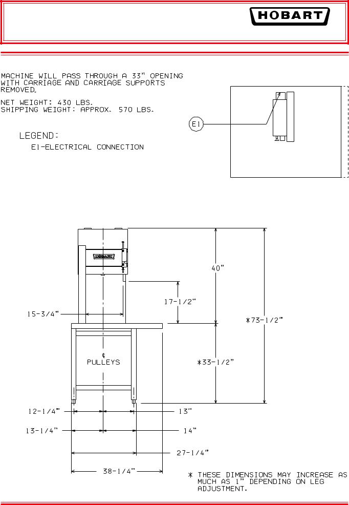
Standard Leg Height: 2" (Std.) 13⁄4" to 21⁄4" Optional Leg Height: 4" 33⁄4" to 41⁄4"
Saw Blade: 5⁄8" wide x 142" long
Capacity: Cutting clearance is 171⁄2" H x 153⁄4" W Weight: Net 430 lbs. Shipping: approximately 570 lbs.
As continued product improvement is a policy of Hobart, specifications are subject to change without notice.
Page 4 of 4 |
F-39903 – 6801 Series Meat Saw |
|
F-39903 (REV. 8/03) |
6801 Meat Saw Technical Manual Page 6 of 51LITHO IN U.S.A. (H-01) |
Printed On Recycled Paper |

I N
S
TRUCT
I ONS
MODEL 6801 MEAT SAW
MODEL
6801 ML-134094
Previous models covered by this manual: 6801 ML-104948
701 S. RIDGE AVENUE
TROY, OHIO 45374-0001
937 332-3000
www.hobartcorp.com
FORM 34405 Rev. B (Sept. 2001)
6801 Meat Saw Technical Manual Page 7 of 51
Installation, Operation, and Care of
MODEL 6801 MEAT SAW
SAVE THESE INSTRUCTIONS
GENERAL
The 6801 Meat Saw is rugged, durable, and easy to clean. The saw is equipped with a water resistant 3 HP electric motor and direct gear drive transmission. The carriage (Fig.1) has stainless steel ball bearings providing easy travel and dependability. The shaped front edge of the carriage is comfortable to the operator's body even when leaned on during movement. The carriage lock is standard.
Table, carriage, pulleys, guides, and wiper assemblies can be quickly removed without tools for ease of cleaning. Moving parts are enclosed but accessible. The blade is guarded above and below the cutting zone. The pusher plate is provided to eliminate the need of handling items close to the blade; it can ride on the right "flanged-end" of the carriage so you keep your hands away from the cutting edge of the blade.
For electrical specifications above 250 volts, a transformer provides a 115 volt control circuit voltage. Thermal overload protection is an option.
One long-life blade is furnished with each saw as standard equipment. This blade cannot be resharpened; replacement blades are available through your local Hobart Service Office.
|
|
|
|
|
|
|
|
|
|
|
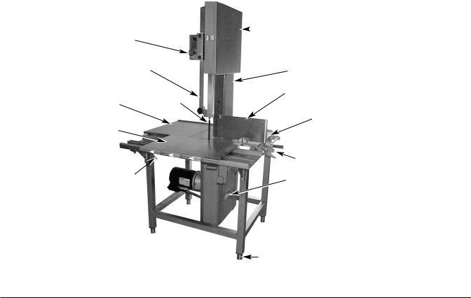
UPPER PULLEY COVER (SST) |
||
|
|
|
|
|
|
|
|
|
|
|
|||
|
|
|
|
|
|
|
|
|
|
|
|
|
|
|
|
SWITCH KNOB |
|
|
|
|
|
|
|
|
|
|
|
|
|
|
|
|
|
|
|
|
|
|
|
||
|
|
|
|
|
|
|
|
|
|
|
|||
|
|
|
|
|
|
|
|
|
|
|
|
|
|
|
|
|
|
|
|
|
|
|
|
|
|
|
|
UPPER GUIDE AND GUARD |
|
|
|
COLUMN GUARD |
|
||||||||
|
|
|
|
|
|
|
|
|
|
|
|
|
|
|
|
|
|
|
|
|
|
|
|
||||
|
|
|
|
|
|
|
|
|
|
|
|
|
|
|
|
|
|
|
|
|
|
|
GAUGE PLATE |
|
|||
|
TABLE (LEFT) |
|
|
SAW BLADE |
|
|
|
|
|
|
|
||
|
|
|
|
|
|
|
|
|
|
||||
|
|
|
|
|
|
|
|
|
|
|
|
|
|
TABLE (RIGHT)
CARRIAGE
 GAUGE PLATE HANDLE
 LOCK LEVER
CARRIAGE LOCK
LOWER COVER (SCRAP PAN)
 LEGS
LEGS
FEET |
|
PL-41385-1 |
© HOBART CORPORATION, 1995, 2000 |
– 2 – |
6801 Meat Saw Technical Manual Page 8 of 51
INSTALLATION
UNPACKING AND ASSEMBLY
Immediately after unpacking the meat saw, check for possible shipping damage. If the meat saw is found to be damaged, save the packaging material and contact the carrier within 15 days of delivery.
Prior to installation, test the electrical service to make sure it agrees with the specifications on the machine data plate located on the column.
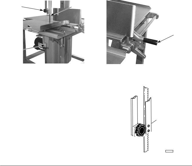
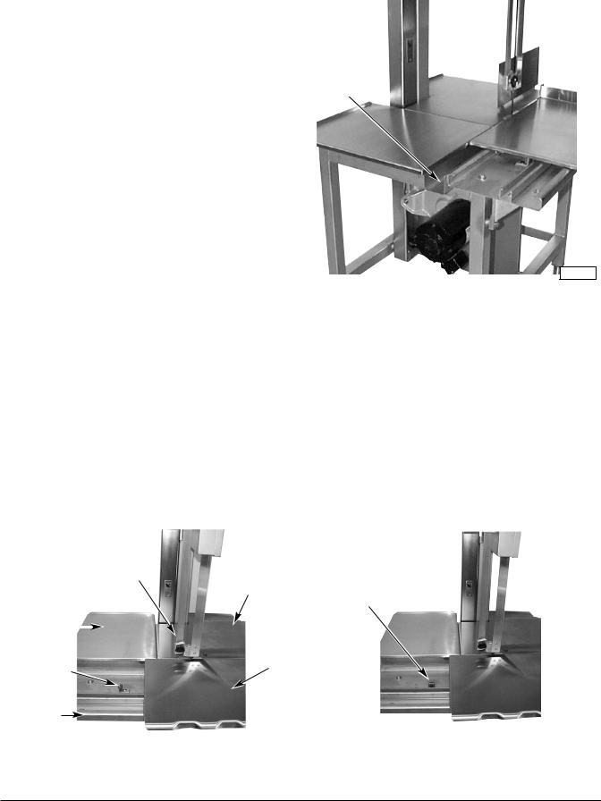
Packed in a packet attached to the table compartment are the pusher plate and the gauge plate handle. Place the pusher plate in its storage location under the carriage support (Fig. 2). Assemble the gauge plate handle to the gauge plate support by screwing the stud into the threaded hole (Fig. 3).
LEVELING
Place the saw in its operating location. Using a spirit level, level the meat saw front-to-back and side- to-side by turning the threaded feet in or out.
HAND KNOB |
SAW BLADE |
|
|
CARRIAGE 
GAUGE PLATE HANDLE
 CARRIAGE
SUPPORT
PUSHER PLATE
|
|
|
PL-41387-1 |
|
PL-41386-1 |
|
|
|
|
|
|
|
|
|
|
Fig. 2 |
|
Fig. 3 |
|
WARNING: DISCONNECT ELECTRICAL POWER AND PLACE A TAG AT THE DISCONNECT SWITCH INDICATING THAT YOU ARE WORKING ON THE CIRCUIT.
SAW BLADE
The saw blade must be installed so the teeth point to the right and down (Fig. 4).
UPPER GUIDE AND GUARD ASSEMBLY
When the saw is off, the hand knob (Fig. 4) can be used to raise or lower the upper guide and guard assembly so the cutting zone is only as high as necessary for the piece being cut. The hand knob is not loosened during raising or lowering — it should remain tightly secure.
Upper Guide
and Guard

 Hand Knob
PL-52107
Fig. 4
– 3 –
6801 Meat Saw Technical Manual Page 9 of 51
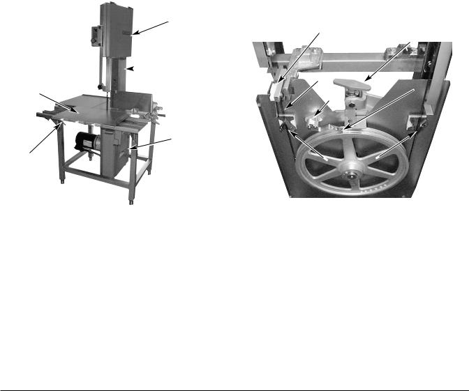
UPPER PULLEY COVER (Plastic)
The plastic upper pulley cover (Fig. 5) should be installed on the two hinge-retainers at the top and securely latched at the bottom during use. To remove the plastic upper pulley cover for cleaning, release the latch at the bottom and remove from the hinge-retainers at the top.
UPPER PULLEY COVER (Stainless Steel)
The stainless steel upper pulley cover (Fig. 1) should be installed on the two hinge pins of the stainless steel upper pulley baffle and securely latched during saw use. To remove the stainless steel upper pulley cover for cleaning, unlatch and open the stainless steel upper pulley cover; then, lift straight up off the hinge pins.
LOWER COVER (Scrap Pan)
During use, the lower cover (Fig. 5) acts as a scrap pan, accumulating bone dust and debris from the blade scrapers and pulley wiper that are located on the lower panel (Fig. 6). To remove the lower cover (scrap pan) for cleaning, release the clip at the top; pull out and lift the lower cover from the groove at the bottom of the lower panel.
UPPER PULLEY COVER (PLASTIC)
|
|
|
|
|
|
|
|
|
TENSION |
|
|
|
|
|
|
|
LOWER BLADE GUIDE |
|
|
||||
|
|
|
|
|
|
ADJUSTER |
|
||||
|
|
|
|
|
|
|
|
|
|
||
|
|
|
|
|
|
|
|
||||
|
|
|
|
|
|
|
|
|
|
|
|
|
|
|
|
|
|
|
|
|
|
|
|
|
|
|
COLUMN GUARD |
|
SAW BLADE |
|
|
|
|
||
|
|
|
|
|
|
|
|||||
|
|
|
|
|
|
|
|
|
|||
|
|
|
|
|
|
|
|
||||
|
|
|
|
|
|
|
|
|
|
|
|
CARRIAGE |
|
|
|
|
|
|
|
|
|
|
|
|
|
|
|
|
|
|
|
|
PULLEY WIPER |
||
|
|
|
|
|
BLOCK |
|
|
|
|||
|
|
|
|
|
|
|
|
|
|||
|
|
|
|
|
|
|
|
|
|
|
|
|
|
|
|
|
|
|
|
|
|
|
|
|
|
|
|
|
|
|
|
|
|
|
|
|
|
LOWER COVER |
|
|
|
|
|
|
|
|
(SCRAP PAN) |
|
|
|
|
|
|
CARRIAGE LOCK |
|
|
|
|
|
BLADE SCRAPERS |
|
|
|
|
|
||||||
|
|
|
|
|
|
|
|
|
|
|
|
|
|
|
|
|
|
|
|
|
PL--41388-1 |
|
|
|
PL-41451-1 |
|
|
|
|
|
|
|
|
|
|
|
Fig. 5 |
|
Fig. 6 |
|||||
BLADE SCRAPERS
Two blade scrapers wipe the blade during sawing to accumulate bone dust and debris inside the lower cover (scrap pan). The front scraper points up and the rear scraper points down (Fig. 6). After the blade is removed, the scrapers can slide off their mounting blocks for cleaning.
PULLEY WIPER
The pulley wiper (Fig. 6) scrapes bone dust or debris from the lower pulley during use. The pulley wiper can be removed for cleaning by springing the wiper up and sliding it off the pins.
– 4 –
6801 Meat Saw Technical Manual Page 10 of 51
LOWER PULLEY
The lower pulley is assembled on the lower pulley shaft. The latch on the lower pulley should be seated in the groove of the pulley shaft (Fig. 7). The lower pulley can be removed after the blade has first been loosened and removed and the lower pulley latch is moved out of the groove of the lower pulley shaft.
UPPER PULLEY
The upper pulley is assembled on the upper pulley shaft. The round retainer on the upper pulley shaft should be positioned out-of-center when latched (Fig. 8). The upper pulley can be removed after the blade has first been loosened and removed and the round retainer is moved to the center of the upper pulley shaft.
LOWER PULLEY |
|
UPPER PULLEY |
|
|
|
LATCH
LATCH
SHAFT
SHAFT
|
|
|
|
|
UNLATCHED |
LATCHED |
|
Fig. 7
PL-41390-1
LATCHED |
UNLATCHED |
Fig. 8
PL-41391-1
COLUMN GUARD
The column guard (Fig. 5) covers the return loop of the moving blade and must always be in place during sawing. To remove the column guard for cleaning or blade change, first remove the right table and the upper pulley cover. You may want to remove the lower cover (scrap pan) as well. Then, lift the column guard up to free it from the two shoulder-screw heads on the column that it hangs from.
TABLES — RIGHT and LEFT
During use, the right and left tables (Fig. 1) are secured underneath by pins and clamps. To remove the tables for cleaning: Raise the gauge plate to its vertical position; lift the right side of the right table up; and, remove the table from the two pins. After the right table is removed, the left table can be removed: Lift the left side of the left table up; and, shift it to the right to free it from the two pins.
– 5 –
6801 Meat Saw Technical Manual Page 11 of 51
SCRAP TRAY
During use, the scrap tray should be installed between the left-hand table and the carriage support (Fig. 9). The scrap tray slides into place, resting on the frame between the carriage support and table. The angled side of the scrap tray is located nearest the blade.
SCRAP TRAY
PL-41392-1
Fig. 9
CARRIAGE
In use, the carriage can roll back and forth between the left carriage stop (Fig. 10) and the right carriage stop, assuming the spring loaded carriage lock (Fig. 5) has not locked the carriage in a stationary position.
To remove the carriage, turn either of the carriage stops 90 degrees so the bumper is toward the rear (Fig. 11). Roll the carriage off either end while lifting it free of the carriage support structure (Fig. 10).
To reinstall the carriage, hold the carriage so the bearings (underneath) are aligned with the carriage support structure. Roll the carriage into place. Return the carriage stops so the carriage is stopped at both ends.
|
|
|
UPPER GUIDE AND GUARD |
|
|
|
|
|
|
|
LEFT CARRIAGE STOP |
|
|
||||
RIGHT TABLE |
|
|
|||||||||||||||
|
|
|
|
|
|
|
|
|
|
|
WITH BUMPER TOWARDS |
|
|
||||
|
|
|
|
|
|
|
|
|
|
|
|||||||
|
|
|
|
|
|
|
|
|
|
|
|
|
|
|
THE REAR |
|
|
|
|
|
|
|
|
|
|
|
|
|
|
|
|
|
|
||
|
|
|
|
|
|
|
|
|
|
|
|
|
|
|
|
|
|
|
LEFT TABLE |
|
|
|
|
|
|
|
|
|
|
|
|
||||
|
|
|
|
|
|
|
|
|
|
|
|||||||
|
|
|
|
|
|
|
|
|
|
|
|
|
|
|
|
||
|
|
|
|
|
|
|
|
|
|
|
|
|
|
|
|
|
|
|
|
|
LEFT |
|
|
|
|
|
|
|
|
|
|
|
|
||
|
|
|
|
|
CARRIAGE |
|
|
|
|
||||||||
|
|
|
CARRIAGE |
|
|
|
|
|
|
|
|
|
|
||||
|
|
|
|
|
|
|
|
|
|||||||||
|
|
|
STOP |
|
|
|
|
|
|
|
|
|
|
||||
|
|
|
|
|
|
|
|
|
|
|
|
|
|||||
|
|
|
|
|
|
|
|
|
|
||||||||
CARRIAGE |
|
|
|
|
|
|
|
|
|
|
|||||||
|
|
|
|
|
|
|
|
|
|
|
|
|
PL-41394-1 |
||||
SUPPORT |
|
|
|
|
|
|
|
|
|
|
|||||||
|
|
|
|
|
|
|
PL-41393-1 |
|
|
|
|
|
|||||
|
|
|
|
|
|
|
Fig. 10 |
|
|
|
|
|
|
|
Fig. 11 |
||
– 6 –
6801 Meat Saw Technical Manual Page 12 of 51

LOWER BLADE GUIDE
The lower blade guide assembly fits in the lower guide holder (Fig. 12). The blade fits in the slots of both the steel saw blade guide and the plastic guide. When the right table is removed and the plastic guide is hinged up, the lower blade guide assembly can be removed for cleaning by lifting it out of the lower guide holder.
The steel saw blade guide is available in various widths depending on the blade being used. Contact Service to change the steel saw blade guide for other blade widths.
LOWER BLADE GUIDE ASSEMBLY
LOWER GUIDE HOLDER
PL-40838-1
Fig. 12
REMOVING THE BLADE
Remove the upper and lower pulley covers. Raise the gauge plate to its vertical position. Remove the right table by lifting its right side and sliding the table to the right to free it from the locating pins. Remove the column guard. Turn the tension adjuster counterclockwise until it stops (this will release tension on the blade by raising the lower pulley). Raise the plastic blade guide on the lower blade guide assembly and release the blade from the upper and lower blade guides. Free the blade from the blade scrapers in the lower pulley area and release it from the pulleys. Remove the blade.
Make sure the pulleys are properly installed and the pulleys are latched (Figs. 7 & 8). Install the new blade with the teeth pointing to the right and down as you face the front of the saw. The blade must fit between the V's on the blade scrapers, in the slots of the upper and lower blade guides, and must not touch any of the pulley flanges. The lower blade guide must be installed after the blade is installed. When the blade is in position, see BLADE TENSION, below, to adjust the tension properly. Refer to LOWER BLADE GUIDE, above, if the blade width of the new blade is different than the old. Reinstall any removed parts.
BLADE TENSION
After the blade has been installed, set the blade tension by turning the tension adjuster clockwise until it stops.
– 7 –
6801 Meat Saw Technical Manual Page 13 of 51

ELECTRICAL CONNECTIONS
WARNING: ELECTRICAL AND GROUNDING CONNECTIONS MUST COMPLY WITH THE APPLICABLE PORTIONS OF THE NATIONAL ELECTRICAL CODE AND/OR OTHER LOCAL ELECTRICAL CODES.
WARNING: DISCONNECT ELECTRICAL POWER SUPPLY AND PLACE A TAG AT THE DISCONNECT SWITCH INDICATING THE CIRCUIT IS BEING WORKED ON.
ELECTRICAL DATA
|
|
Fuse |
|
Circuit Breaker |
||
|
|
|
|
|
|
|
Model |
Volts / Hertz / Phase |
Minimum |
|
Maximum |
Minimum |
Maximum |
|
|
Circuit Ampacity |
|
Fuse Size |
Circuit Ampacity |
Circuit Breaker Size |
|
|
AMPS |
|
AMPS |
AMPS |
AMPS |
|
|
|
|
|
|
|
|
230 / 60 / 1 |
25 |
|
25 |
30 |
30 |
6801 |
|
|
|
|
|
|
200 - 230 / 60 / 3 |
20 |
|
20 |
20 |
20 |
|
|
|
|
|
|
|
|
|
460 / 60 / 3 |
15 |
|
10 |
15 |
15 |
|
|
|
|
|
|
|
Compiled in accordance with the National Electrical Code, NFPA 70, latest edition.
A 7/8" diameter hole for 1/2" trade size conduit is located at the upper rear of the column. Use watertight connections. Refer to Electrical Data, the machine data plate, and the wiring diagram located on the machine when making the electrical connection. Connect the electrical power supply leads to the pigtail leads; use copper wire rated at least 60°C for the connection.
CHECK MOTOR ROTATION (Three-Phase Machines)
If the motor does not rotate so the teeth of the saw blade run downward as you look at the cutting zone, correct the rotation using the following procedure:
WARNING: DISCONNECT ELECTRICAL POWER SUPPLY AND PLACE A TAG AT THE DISCONNECT SWITCH INDICATING THAT YOU ARE WORKING ON THE CIRCUIT.
Interchange any two of the incoming power supply leads. Reconnect the power supply and turn the saw momentarily on and off to verify correct rotation.
CONTROL BOX HEATER
The meat saw has a heater in the control box to keep the controls dry. The heater is automatically ON when the machine is electrically connected. The meat saw should be connected to the power supply EXCEPT when performing assembly, disassembly, cleaning, or maintenance on the saw.
CLEAN SAW BEFORE USE
The saw must be thoroughly cleaned and sanitized after installation and before use. Refer to Cleaning, page 11.
– 8 –
6801 Meat Saw Technical Manual Page 14 of 51

OPERATION
SAFETY DEVICES INCORPORATED IN THIS SAW MUST BE IN THEIR CORRECT OPERATING POSITIONS ANYTIME THE SAW IS IN USE.
SAFETY FEATURES
Upper Guide and Guard Assembly
Before turning the saw on, raise or lower the upper guide and guard assembly by grasping the hand knob and sliding up or down so the cutting zone is only as high as necessary for the piece being cut.
Doors, Covers, and Guards
All doors, covers, and guards must be in their operating position (closed) while the machine is running.
Pusher Plate
Always keep hands well back from the blade and maintain control of the product. Use the pusher plate as described (page 10) and it will be unnecessary to hold your hand near the cutting edge of the saw blade.
CONTROLS
Switch Knob |
PULL turns the saw On. PUSH turns the saw Off. |
SAWING
Place product on carriage. Set the upper guide and guard assembly and the gauge plate before starting the machine.
If using the traveling carriage . . .
Stand in front of machine. Lean lightly against the front of the carriage as you move the carriage to the left, passing the product through the blade at a steady and uniform rate.
Use your left hand to remove and stack cuts, always reaching behind the blade. NEVER REACH IN FRONT OF THE BLADE. Return the carriage to the right, pulling the product toward you and away from the blade.
If using the stationary carriage . . .
The carriage may be locked in a stationary position by pulling the spring loaded carriage lock out, rotating it 90° and sliding the carriage until the lock engages (Fig. 13). To unlock the carriage, pull the carriage lock out and rotate it 90° so it rests on its bracket. When sawing with stationary table, observe the same safety procedure of reaching behind the blade when removing or stacking product. NEVER REACH IN FRONT OF THE BLADE.
UPPER GUIDE AND GUARD
CARRIAGE
CARRIAGE LOCK
PL-41395-1
Fig. 13
– 9 –
6801 Meat Saw Technical Manual Page 15 of 51
GAUGE PLATE
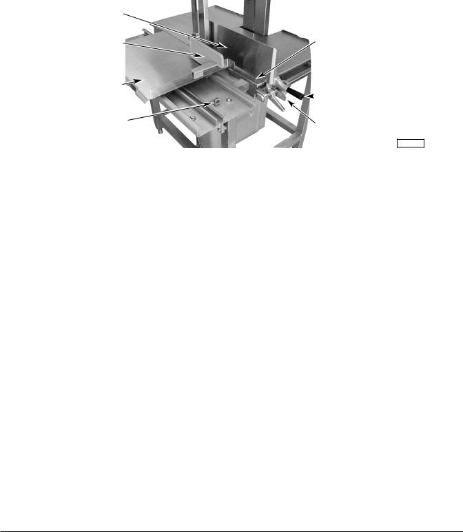
When making several cuts of the same thickness (or when using the pusher plate), set the gauge plate as desired (Fig. 14) by pushing the lock lever and sliding the gauge plate to the thickness you want. A reference scale on the table indicates the thickness of cut. If the gauge plate is not needed, you may release the lock lever and move the gauge plate to the rear; or raise the gauge plate to a vertical position to keep it out of the way.
GAUGE PLATE
|
PUSHER PLATE |
|
|
|
REFERENCE SCALE |
|
|
|
|
|
|
|
|
|
|
|
CARRIAGE |
|
|
|
|
||
|
|
|
|
|
|
|
|
|
|
|
|
|
|
GAUGE PLATE HANDLE |
|
|
|
|
|
|
|
|
|
|
|
|
|
|
|||
|
|
|
|
|
|
|
|
RIGHT CARRIAGE STOP |
|
|
GAUGE PLATE LOCK LEVER |
|
|||
|
|
|
|
|
|
|
|
PL-41396-1
Fig. 14
PUSHER PLATE
The pusher plate is used to hold meat against the gauge plate when slicing short ends. A slot in the pusher plate and a stop on the right "flanged-end" of the carriage is provided for proper positioning of the pusher plate (Fig. 14). Hold the pusher plate handle with your right hand and always maintain a safe distance from the blade. When not in use, keep the pusher plate under the carriage support (Fig. 2).
– 10 –
6801 Meat Saw Technical Manual Page 16 of 51
Loading...