


5212F

I
N
S
T
R
U
C
T
I
O
N
S
MODEL 5212 & 5212F MEAT SAWS
MODEL
5212 ML-31665
5212F ML-31666
EXECUTIVE OFFICES
701 RIDGE AVENUE
TROY, OHIO 45374-0001
FORM 19465 (11-95)
Installation, Operation, and Care of
MODEL 5212 & 5212F MEAT SAWS
SAVE THESE INSTRUCTIONS
GENERAL
The 5212 Meat Saw is rugged, durable, and easy to clean. The carriage (Fig.1) has stainless steel ball
bearings providing easy travel and dependability. The shaped front edge of the carriage is comfortable
to the operator's body even when leaned on during movement. The carriage lock is standard. Instead
of the rolling carriage, model 5212F has a stationary cutting table often used for poultry cutting.
Table, carriage, pulleys, guides, and wiper assemblies can be quickly removed without tools for ease
of cleaning. Moving parts are enclosed but accessible. The blade is guarded above and below the
cutting zone. The pusher plate is provided to eliminate the need of handling items close to the blade;
it can ride on the right "flanged-end" of the carriage so you keep your hands away from the cutting edge
of the blade.
The 5212 and 5212F Meat Saws have a 2 HP motor controlled by a push-pull switch knob located on
the front of the saw (Fig. 1). For electrical specifications above 250 volts, a transformer provides a 115
volt control circuit voltage (optional on lower voltages). Thermal overload protection is an option.
One long-life blade is furnished with each saw as standard equipment. This blade cannot be
resharpened; replacement blades are available through your local Hobart Service Office.
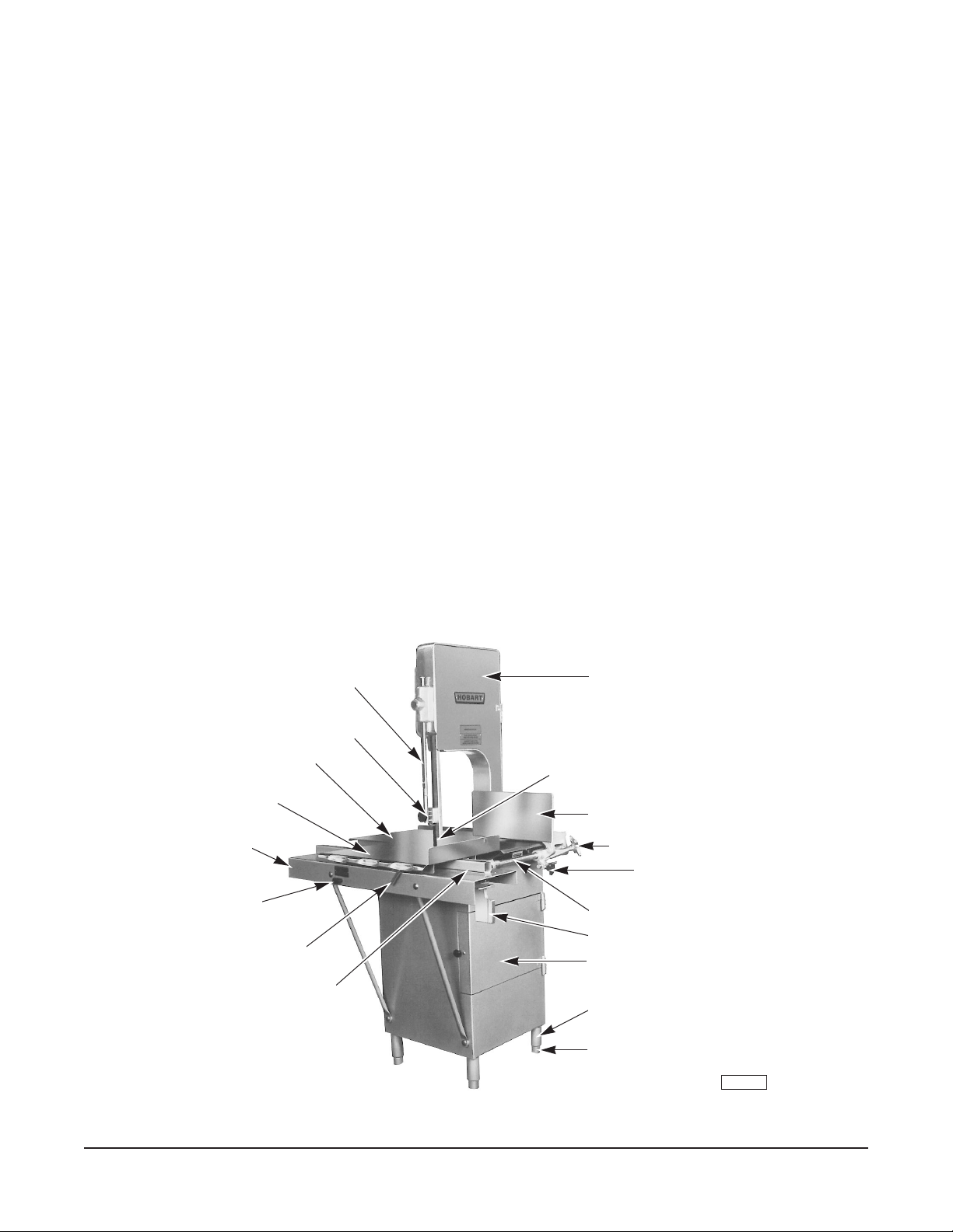
Slide Rod for Upper Guide and Guard
Upper Guide and Guard
Table
Carriage
Carriage Support
Switch Knob
Carriage Lock
Carriage Guide
Head Door
Saw Blade
Gauge Plate
Gauge Plate Adjusting Knob
Gauging Pin Hand Knob
Gauge Plate Rack
Pusher Plate
Base Door
Legs
Fig. 1
– 2 –
Feet
PL-40801-1

INSTALLATION
UNPACKING AND ASSEMBLY
Immediately after unpacking the meat saw, check for possible shipping damage. If the meat saw is
found to be damaged, save the packaging material and contact the carrier within 15 days of delivery.
Prior to installation, test the electrical service to make sure it agrees with the specifications on the
machine data plate located on the base.
Packed in the scrap pan in the base compartment are the pusher plate, feet, and set screws. Place
the pusher plate in its storage location under the carriage support (Fig. 1). Remove the four shipping
bolts from the underside of the skid. Apply Lubriplate 630AA grease (supplied) to the threaded studs
of the four feet; assemble the feet to the legs (Fig. 1). Tilt to one side and install two feet, then tilt the
other way and install the two remaining feet.
LEVELING
Place the saw in its operating location. Using a spirit level, level the meat saw front-to-back and sideto-side by turning the feet in or out. Lock feet in place using set screws furnished.
WARNING: DISCONNECT ELECTRICAL POWER AND PLACE A TAG AT THE DISCONNECT
SWITCH INDICATING THAT YOU ARE WORKING ON THE CIRCUIT.
SAW BLADE
The saw blade must be installed so the teeth point to
the right and down (Fig. 2).
UPPER GUIDE AND GUARD ASSEMBLY
When the saw is off, the hand knob (Fig. 2) can be
used to raise or lower the upper guide and guard
assembly so the cutting zone is only as high as
necessary for the piece being cut. The hand knob is
not loosened during raising or lowering — it should
remain tightly secure.
UPPER PULLEY WIPER
The upper pulley wiper (Fig. 4) is attached to the head
by a threaded stud and knob; it wipes the upper pulley
and blade during use.
HEAD DOOR
The head door (Fig. 1) should be installed on the two
hinge pins and closed during saw use. To remove the
head door for cleaning, open the door and lift straight
up off the hinge pins.
Upper
Back-Up
Block
Upper
Guide
Upper
Blade
Guard
Hand
Knob
PL-40777-1
Fig. 2
– 3 –
 Loading...