Hobart 4346 User Manual

|
I N |
|
|
S |
|
|
TR |
|
|
UC |
|
|
TI |
O |
|
|
N |
|
|
S |
MODEL 4346 MIXER-GRINDER |
|
|
MODEL |
|
|
4346 ML-104658 |
R.H. Standard Hopper (Without Side Feed Opening) |
|
ML-104659 L.H. Standard Hopper (Without Side Feed Opening) |
||
ML-104662 |
R.H. Optional Hopper (With Side Feed Opening) |
|
ML-104663 |
L.H. Optional Hopper (With Side Feed Opening) |
|
WORLD HEADQUARTERS
701 RIDGE AVENUE
TROY, OHIO 45374-0001
FORM 33738 (10-96)

Installation, Operation, and Care of
MODEL 4346 MIXER-GRINDER
SAVE THESE INSTRUCTIONS
GENERAL
The Model 4346 Mixer-Grinder is equipped with a 71/2 HP motor which rotates the mixing arm at 29 RPM and the worm at 222 RPM. The 4346 is designed to use a #32 (42/46) size knife and plate (knives and plates are available at extra cost but not included with grinder). Do not use a plate with hole size smaller than 3/32".
The hopper can hold up to 215 pounds for first grind, depending on type of product; up to 240 pounds for second grind. The machine can grind at a rate of 55 to 60 pounds of fresh boneless beef per minute, first or second cut through a 1/8" plate. Frozen meat must be tempered to 24°F or higher before grinding and can be in flake or stick form. Pork can be ground first cut through a 3/4" breaker plate; and second cut through a 3/16" plate at 60 to 65 pounds per minute.
Optional equipment, available at extra cost, includes the following:
1)Flexible power supply cord and plug. Either a receptacle or a pendant type connector is available. The receptacle requires a type FD electrical box (not supplied).
2)Legs with casters (4 lengths are available). NOTE: Machines with casters are equipped with flexible power supply cord and plug. Either a receptacle or a pendant type connector is available. The receptacle requires a type FD electrical box (not supplied).
3)Legs without casters (4 lengths are available).
4)Pneumatic foot switch (accessory).
5)A side feed inlet can be ordered (and factory installed) for either the rightor left-hand side of the hopper to allow product from a companion first cut grinder to feed directly into the hopper. A plug assembly is available for use when the side inlet hole is not in use.
6)#32 size knives and plates.
NOTE: With the proper adapter ring, the mixer-grinder can be connected to other grinders having either a #32 (42/46), #52, or #56 chopper end, assuming the height of the side feed inlet can be met.
INSTALLATION
Immediately after unpacking the mixer-grinder, check for possible shipping damage. If the machine is found to be damaged, save the packaging material and contact the carrier within 15 days of delivery.
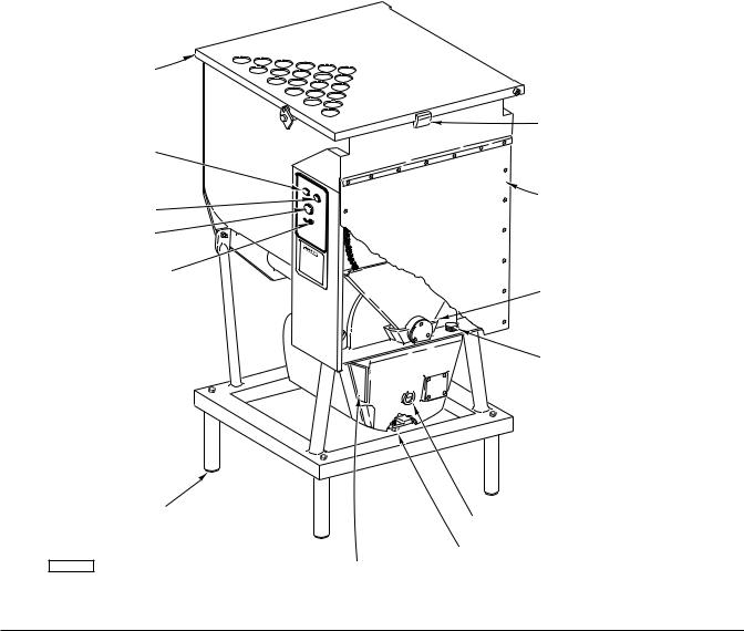
Prior to installation, test the electrical service to make sure it agrees with the specifications on the machine data plate (Fig. 3).
PNEUMATIC FOOT SWITCH
Remove the cap from the barbed fitting adjacent to the electrical supply junction compartment (Fig. 1) and connect the tube from the pneumatic foot switch onto the barbed fitting using the clamp provided. A pliers will be needed to squeeze the clamp open during installation. Avoid kinking the tube.
© HOBART CORPORATION, 1996 |
– 2 – |

LEGS OR CASTERS
With the mixer-grinder securely elevated using the base frame for support, bolt the leg or caster assemblies through the corner holes using 5/8" bolts and lockwashers, provided.
LEVELING
Adjust the feet (or caster legs) so the mixer-grinder is level, both front-to-back and side-to-side.
CHECK GEAR CASE LUBRICANT
Oil is installed in the gear case at the factory. Make sure oil is at the proper level by checking the oil level sight gauge (Fig. 1). If it is necessary to add oil, unscrew the retaining screws and remove the rear panel (Fig. 1). Remove the oil fill plug (Fig. 1) and add Mobil DTE HM oil until the oil level is brought to the center of the oil level sight gauge.
CHECK CHAIN LUBRICANT RESERVOIR
Oil is added to the chain reservoir at the factory and sealed at the bottom of the splash shield with a silicone rubber sealant for shipping purposes. With the rear panel removed, remove the sealant from around the chain reservoir (Fig. 1) and inspect the oil level. Replenish as necessary with MPO-30 Multi-Purpose Oil.
HOPPER GUARD
HOPPER GUARD INTERLOCK
MIX SWITCH
REAR PANEL
MIX-GRIND SWITCH STOP SWITCH
FOOT SWITCH ON-OFF
SEALANT ON CHAIN RESERVOIR
OIL FILL PLUG
LEVELING FOOT |
OIL LEVEL SIGHT GAUGE |
|
|
|
DRAIN PLUG |
PL-52462 |
ELECTRICAL SUPPLY JUNCTION COMPARTMENT |
|
Fig. 1 |
– 3 –
 Loading...