


Solid State Color TV
32GX01B |
36GX01B |
32UX01S |
36UX01S |
|
|
OPERATING GUIDE |
|
|
|
IMPORTANT SAFEGUARDS |
2-4 |
|
FIRST TIME USE |
5-19 |
|
|
|
THE REMOTE CONTROL |
20-31 |
I D |
F A V |
SET UP CUSTOM VIDEO AUDIO THEATER
EASY GRAPHIC GUIDE |
|
ON-SCREEN DISPLAY |
32-52 |
USEFUL INFORMATION INDEX 53-60
As an ENERGY STAR¤ Partner, Hitachi, Ltd. has deternimed that this product meets the ENERGY STAR¤ guidelines for energy efficiency.
IMPORTANT
Follow all warnings and instructions marked on this Color Television.
WARNING |
RISK OF ELECTRIC SHOCK |
DO NOT OPEN |
CAUTION: TO REDUCE THE RISK OF ELECTRIC SHOCK, |
DO NOT REMOVE COVER (OR BACK). |
NO USER SERVICEABLE PARTS INSIDE. |
REFER SERVICING TO QUALIFIED SERVICE PERSONNEL. |
The lightning flash with arrowhead symbol, within an equilateral triangle, is intended to alert the user to the presence of uninsulated dangerous voltage within the product s enclosure that may be of a sufficient magnitude to constitute a risk of electric shock to persons.
The exclamation point within an equilateral triangle, is intended to alert the user to the presence of important operating and maintenance (servicing) instructions in the literature accompanying the appliance.
WARNING:
TO PREVENT FIRE OR SHOCK HAZARD, DO NOT EXPOSE
THIS COLOR TELEVISION TO RAIN OR MOISTURE.
NOTE: ¥ There are no user serviceable parts inside the Color Television.
¥Model and serial numbers are indicated on back side of the Color Television.
¥This Color Television is not intended for use in a computer room.
CAUTION: Adjust only those controls that are covered in the instructions, as improper changes or modifications not expressly approved by HITACHI could void the user s warranty.
CAUTION: TO PREVENT ELECTRIC SHOCK, MATCH WIDE BLADE OF PLUG TO WIDE SLOT, FULLY INSERT.
MODIFICATIONS: The FCC requires the user to be notified that any changes or modifications made to this device that are not expressly approved by Hitachi America, Ltd. Home Electronics Division may void the user s warranty.
POWER SOURCE
This Color Television is designed to operate on 120 Volts 60Hz, AC current. Insert power cord into a 120 Volt 60Hz outlet.
TO PREVENT ELECTRIC SHOCK, DO NOT USE THE COLOR TELEVISION S (POLARIZED) PLUG WITH AN EXTENSION CORD, RECEPTACLE, OR OTHER OUTLET UNLESS THE BLADES AND GROUND TERMINAL CAN BE FULLY INSERTED TO PREVENT BLADE EXPOSURE.
NEVER CONNECT THE COLOR TELEVISION TO 50HZ, DIRECT CURRENT, OR ANYTHING OTHER THAN THE SPECIFIED VOLTAGE.
NOTE: |
|
|
|
|
|
This Color Television receiver will display television closed captioning, ( |
CC |
or |
|
), in accordance |
|
|
with paragraph 15.119 of the FCC rules. |
|
|
||
|
|
|
|
|
|
CAUTION: Never remove the back cover of the Color Television as this can expose you to very high voltages and other hazards. If the television does not operate properly, unplug the television and call your authorized dealer or service shop.
2
IMPORTANT
IMPORTANT SAFEGUARDS
CAUTION: |
· |
Read all of these instructions. |
SAFETY POINTS YOU SHOULD KNOW ABOUT |
|
· |
Save these instructions for later use. |
YOUR HITACHI COLOR TELEVISION |
|
· |
Follow all warnings and instructions marked |
|
|
|
on the television. |
|
Our reputation has been built on the quality, performance, and ease of service of HITACHI televisions.
Safety is also foremost in our minds in the design of these units. To help you operate these products properly, this section illustrates safety tips which will be of benefit to you. Please read it carefully and apply the knowledge you obtain from it to the proper operation of your HITACHI television.
Please fill out your warranty card and mail it to HITACHI. This will enable HITACHI to notify you promptly in the improbable event that a safety problem should be discovered in your product model.
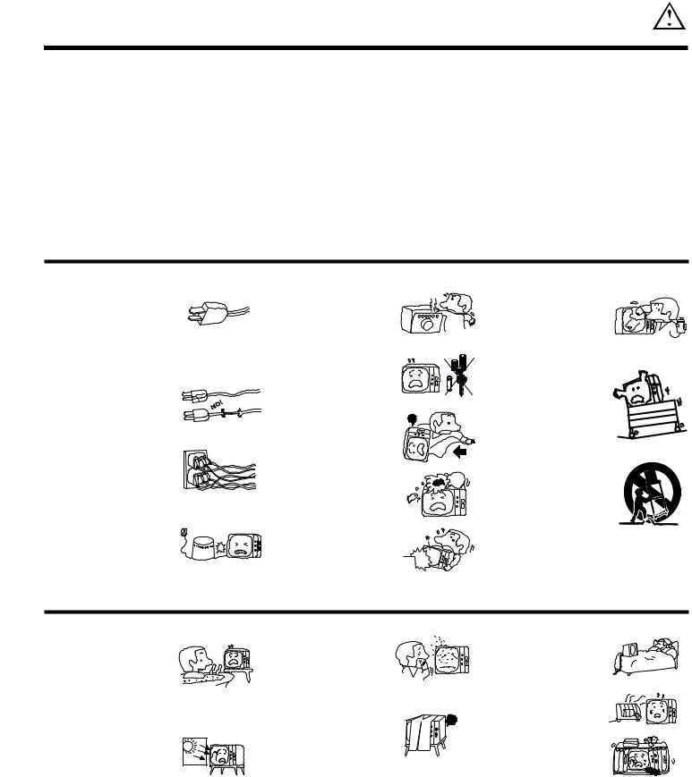
FOR YOUR PERSONAL SAFETY
1.This television set is equipped with a polarized alternating-current line plug (a plug having one blade wider than the other.) This plug will fit into the power outlet only one way. This is a safety feature. If you are unable to insert the plug fully into the outlet, try reversing the plug. If the plug should still fail to fit, contact your electrician to replace your obsolete outlet. Do not defeat the safety purpose of the polarized plug.
2.When the power cord or plug is damaged or frayed, unplug the television from the wall outlet and refer servicing to qualified service personnel.
3.Do not overload wall outlets and extension cords as this can result in fire or electric shock.
4.Do not allow anything to rest on or roll over the power cord, and do not place the television where the power cord is subject to traffic or abuse. This may result in a shock or fire hazard.
5.Do not attempt to service the television yourself as opening or removing covers may expose you to dangerous voltage or other hazards. Refer all servicing to qualified service personnel.
6.Never push objects of any kind into the television s cabinet slots as they may touch dangerous voltage points or short out parts that could result in a fire or electric shock. Never spill liquid of any kind on the television.
7.If the television has been dropped or the cabinet has been damaged, unplug the television from the wall outlet and refer servicing to qualified service personnel.
8.If liquid has been spilled into the television set, unplug it from the wall outlet and refer service to qualified service personnel.
9.Do not subject your television to impact of any kind. Be careful not to damage the picture tube surface.
10.Unplug the television from the wall outlet before cleaning. Use a damp cloth for cleaning. Do not use liquid or aerosol cleaners.
|
11-1. Do not place the television on an |
|
|
unstable cart, stand, or table. The |
|
|
television may fall, |
causing |
|
serious injury to a child or an |
|
|
adult, and serious damage to the |
|
|
appliance. Use only with a cart or |
|
|
stand recommended |
by the |
|
manufacturer, or sold with the |
|
|
television. Wall or shelf mounting |
|
|
should follow the manufacturer s |
|
|
instructions, and should use a |
|
|
mounting kit approved by the |
|
|
manufacturer. |
|
11-2. An appliance and cart combination should be moved with care. Quick stops, excessive force, and uneven surfaces may cause the appliance and cart combination to overturn.
PROTECTION AND LOCATION OF YOUR TELEVISION
12. |
Do not use the television near |
|
14. Avoid dusty |
places. Accumulated |
|||||
|
water, for example, near a bathtub, |
|
dust inside the chassis may cause |
||||||
|
washbowl, kitchen sink, or laundry |
|
failure of the television when high |
||||||
|
tub, in a wet basement, or near a |
|
humidity persists. |
|
|||||
|
swimming pool, etc. |
|
|
|
|
|
|
||
¥ |
Never expose the television to |
|
15. The television has slots or openings |
||||||
|
in the cabinet for ventilation |
||||||||
|
rain or water. If the set has been |
|
purposes |
which provide reliable |
|||||
|
exposed to rain or water, unplug |
|
operation |
of |
the receiver |
and |
|||
|
television from wall outlet and |
|
protect |
the |
television |
from |
|||
|
refer |
to |
qualified |
service |
|
overheating. These openings must |
|||
|
personnel. |
|
|
|
not be blocked or covered. |
|
|||
13. |
Choose a place where light |
|
¥ Never cover the slots or openings |
||||||
|
(artificial or sunlight) does not |
|
with cloth or other material. |
|
|||||
|
shine directly on the screen. |
|
|
|
|
|
|||
¥ Never block the bottom ventilation slots of the television by placing it on a bed, sofa, rug, etc.
|
|
|
|
¥ |
Never place the television near or |
|
over a radiator or heat register. |
¥ |
Never place the television in a built-in |
|
enclosure unless proper ventilation |
|
is provided. |
3
IMPORTANT
PROTECTION AND LOCATION OF YOUR TELEVISION
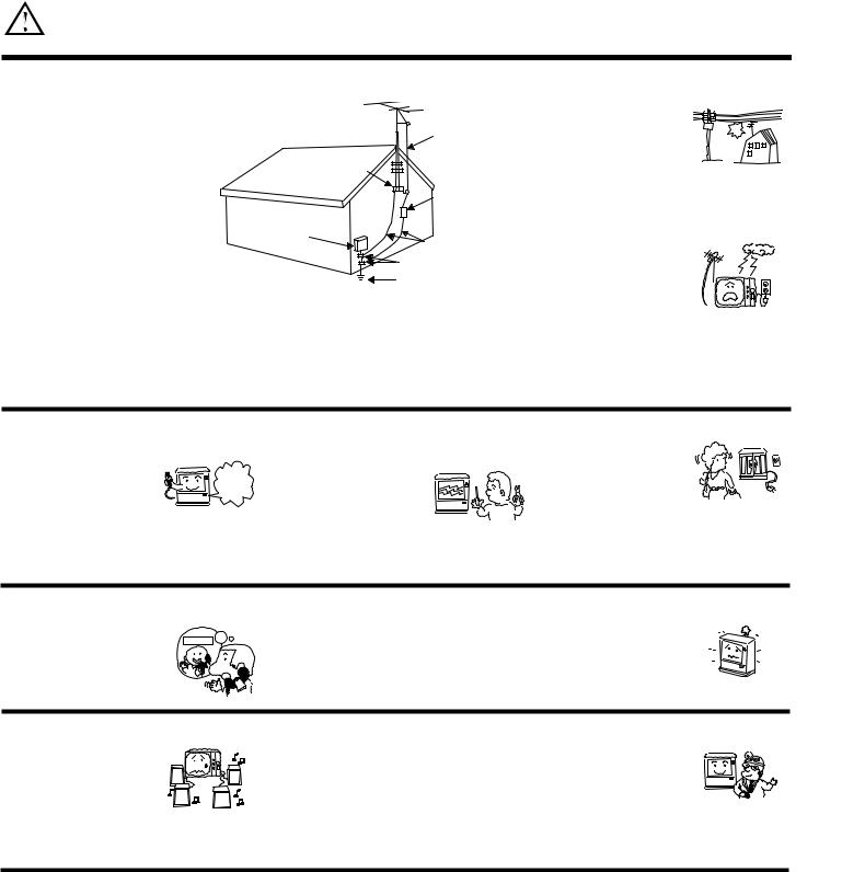
16-1. If an outside antenna is connected to the television, be sure the antenna system is grounded so as to provide some protection against voltage surges and built-up static charges. Section 810 of the National Electrical Code, NFPA No. 70-1975, provides information with respect to proper grounding of the mast and supporting structure, grounding of the lead-in wire to an antenna discharge unit, size of grounding conductors, location of antenna discharge unit connection to grounding electrode, and requirements for the grounding electrode.
16-2. Note to CATV system installer:
(Only for television with CATV reception). This reminder is provided to call the CATV system installer s attention to Article 82040 of the NEC that provides guidelines for proper grounding and, in particular, specifies that the cable ground shall be connected to the grounding system of the building, as close to the point of cable entry as practical.
EXAMPLE OF ANTENNA GROUNDING AS PER NATIONAL ELECTRICAL CODE INSTRUCTIONS.
17.An outside antenna system should not be located in the vicinity of overhead power lines or other electrical lights or power circuits, or where it can fall into such power lines or circuits. When installing an outside antenna system, extreme care should be taken to keep from touching such power lines or circuits as contact with them might be fatal.
18.For added protection for the television during a lightning storm, or when it is unused for long periods of time, unplug it from the wall outlet and disconnect antenna. This will prevent damage due to lightning and power-line surges.
OPERATION OF YOUR TELEVISION
19.This television should be operated only from the type of power source indicated on the marking label. If you are not sure of the type of power supply at your home, consult your dealer or local power company. For televisions designed to operate from battery power, refer to the operating instructions.
20.If the television does not operate normally by following the operating instructions, unplug the television
from the wall outlet and refer
|
servicing to |
qualified |
service |
|
personnel. |
Adjust only |
those |
|
controls that are covered in the instructions as improper adjustment of other controls may result in damage and will often require extensive work by a qualified service technician to restore the television to normal operation.
21.If your television is to remain unused for a period of time, (such as when going on a holiday), turn
the television OFF and unplug it from the wall outlet.
IF THE TELEVISION DOES NOT OPERATE PROPERLY
22. If you |
are unable to restore |
|
23. Whenever the television is |
||
normal |
operation by |
following |
|
damaged or fails, or if there is a |
|
the detailed procedure |
in |
your |
|
distinct change in performance |
|
operating instructions, |
do |
not |
|
that indicates a need for service, |
|
attempt any further adjustments. |
|
unplug the television and have it |
|||
Unplug the television and call |
|
checked by a qualified service |
|||
your dealer or service technician. |
|
technician. |
|||
24.It is normal for some televisions to make occasional snapping or popping sounds, particularly when being turned on or off. If the snapping or popping is continuous or frequent, unplug the set and consult your dealer or service technician.
FOR SERVICING AND MODIFICATION
25.Do not use attachments not recommended by the television manufacturer as they may cause hazards.
26.If replacement parts are required, be sure the service technician has used replacement parts specified by the manufacturer that have the same characteristics as the original part. Unauthorized substitutions may result in fire, electric shock, or other hazards.
27. Upon completion of any service or |
|
repairs to the television, ask the |
|
service technician to perform |
|
routine safety checks to determine |
|
that the television is in safe |
|
operating condition. |
|
PICTURE CAUTIONS
Picture Burn Prevention
¥Continuous on-screen displays such as video games, stock market quotations, computer generated graphics, and other fixed (non-moving) patterns can cause permanent damage to television receivers. Such PATTERN BURNS constitute misuse and are NOT COVERED by your HITACHI Factory Warranty.
¥When using Picture-in-Picture function, the sub-picture should not be left permanently in one corner of the screen or a PATTERN BURN may develop over a long period of time.
Public Viewing of Copyrighted Material
Public viewing of programs broadcast by TV stations and cable companies, as well as programs from other sources, may require prior authorization from the broadcaster or owner of the video program material.
4
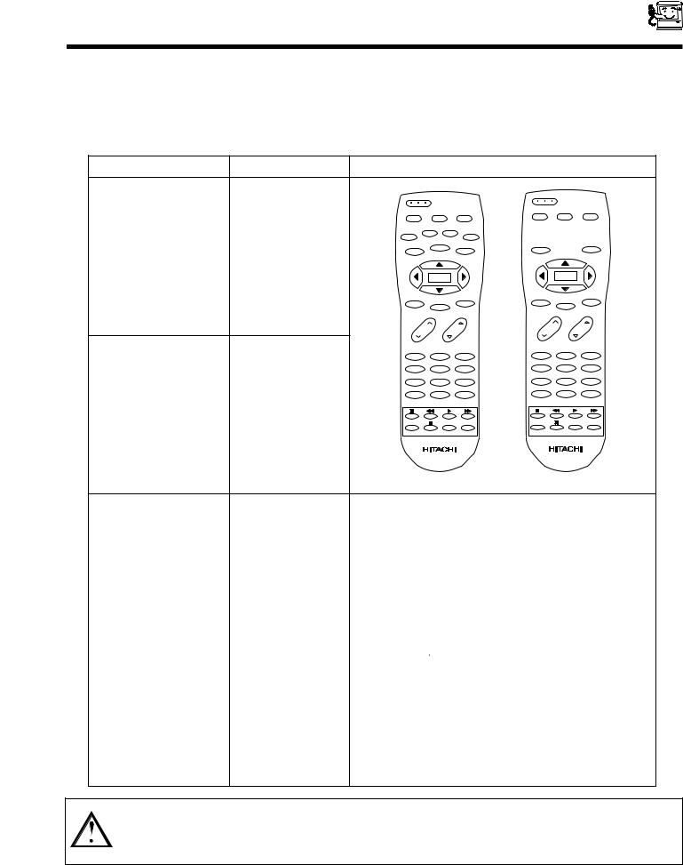
ACCESSORIES
Check that you have the following accessories before disposing of the packing material.
1.Remote Control Unit.
2.Two AA size, 1.5V batteries (For Remote Control Unit).
For information regarding how to obtain these accessories, please call TOLL FREE 1-800-448-2244 for your nearest HITACHI Authorized Parts Distributor in the continental United States. For Alaska please contact your nearest HITACHI regional office.
PARTS NAME |
PART NO. |
|
|
|
ILLUSTRATION |
|
|
|
|
|
|
POWER |
|
|
POWER |
|
|
|
|
|
|
|
|
|
||
|
|
TV |
CBL/SAT |
DVD/VCR |
TV |
CBL/SAT |
DVD/VCR |
|
|
|
|
|
|
||||
36UX01S |
|
PIP |
SWAP |
MOVE |
|
|
|
|
32UX01S |
|
|
|
FREEZE |
|
|
|
|
HL01421 |
HELP |
PIP CH |
TV/VCR |
HELP |
|
TV/VCR |
||
CLU-431UG |
|
|
|
|
|
|
|
|
|
|
|
|
|
|
|
|
|
REMOTE CONTROL |
|
|
MENU |
|
|
MENU |
|
|
|
|
MUTE |
EXIT |
LAST CH |
MUTE |
EXIT |
LAST CH |
|
|
|
|
|
|
|
|||
|
|
VOL |
CH |
VOL CH |
||||
|
|
1 |
|
2 |
3 |
1 |
2 |
3 |
|
|
4 |
|
5 |
6 |
4 |
5 |
6 |
36GX01B |
|
7 |
|
8 |
9 |
7 |
8 |
9 |
|
INPUT |
|
0 |
SLEEP |
INPUT |
0 |
SLEEP |
|
32GX01B |
HL01422 |
|
|
|
|
|
|
|
CLU-381UG |
REC |
|
C.S. |
RECALL |
REC |
C.S. |
RECALL |
|
|
|
|||||||
REMOTE CONTROL |
|
|
|
|
|
|
|
|
|
|
|
CLU-431UG |
|
|
CLU-381UG |
|
|
|
|
CUSTOM HITACHI |
|
||||||||||
32V TELEVISION STAND |
|
TELEVISION STAND |
|
||||||||||
H530022 |
|
||||||||||||
SP316B |
|
||||||||||||
(Not included, order separately) |
|
Excellent for VCR and video- |
|
||||||||||
|
|
tape storage. Special features |
|
||||||||||
|
|
include curved smoked glass |
|
||||||||||
|
|
doors and an adjustable shelf. |
|
||||||||||
32V TELEVISION STAND |
|
Available in Black. |
|
||||||||||
H530023 |
|
||||||||||||
SP317B |
|
||||||||||||
(upgrade) |
|
|
|
|
|
|
|
|
|
|
|||
(Not included, order separately) |
|
|
|
|
|
|
|
|
|
|
|
|
|
|
|
|
|
|
|
|
|
|
|
|
|
|
|
36V TELEVISION STAND |
|
|
|
|
|
|
|
|
|
|
|
|
|
SP351B |
H530024 |
|
|
|
|
|
|
|
|
|
|||
(Not included, order separately) |
|
|
|
|
|
|
|
|
|
|
|
|
|
|
|
|
|
|
|
|
|
|
|
|
|
|
|
CAUTION: Color television stand model SP316B or SP317B is designed for use only with a 32 inch or smaller color television set. Television stand model SP351B is designesd for use with a 36 inch or smaller television set. Use of a smaller stand, a non Hitachi recommended stand or a generic stand may result in instability, causing possible injury.
5
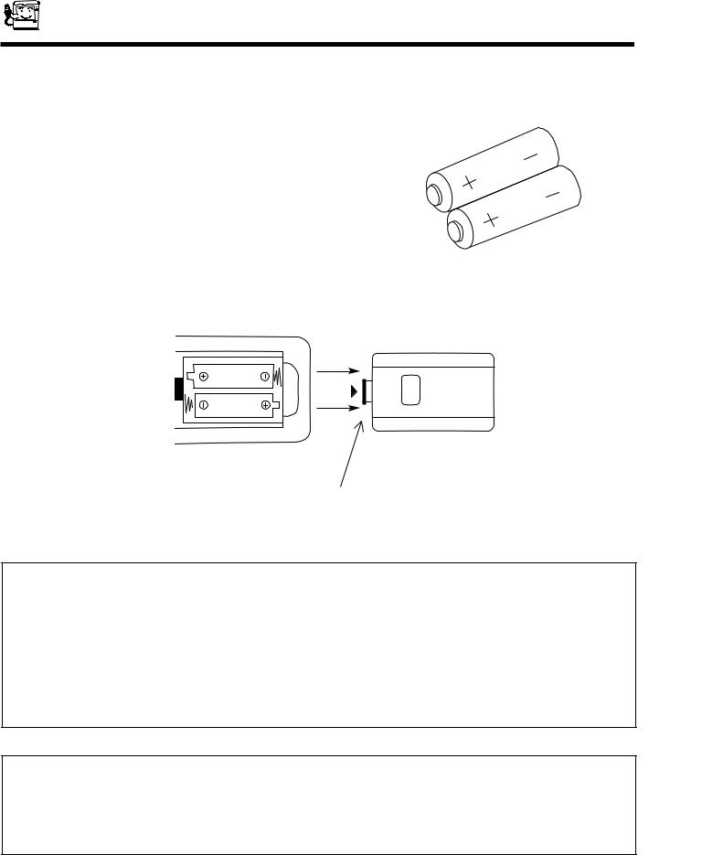
REMOTE CONTROL BATTERY INSTALLATION
AND REPLACEMENT
1.Open the battery cover of the remote control by pushing the notched part of the cover with your fingers.
2.Insert two new AA size batteries for the remote control. When replacing old batteries, push
them towards the springs and lift them out.
3.Match the batteries to the (+) and (-) marks in the battery compartment.
4.Replace the cover.
BOTTOM VIEW
Push in and lift up on tab to
Lift up on tab to remove back cover.
remove back cover.
CAUTION:
1.If your television set is to remain unused for a long period of time, for instance when you go on vacation, unplug the television from the wall outlet.
2.Do not subject the remote control to shocks such as dropping it on the floor, etc. Precision parts may be damaged.
3.Do not allow the remote control to become wet and avoid placing it in areas of high humidity. Do not leave it on or near a heater. Excess heat or moisture may cause the unit to cease operation.
4.If the batteries become exhausted, remote control operation may become erratic or stop altogether. Replace the old batteries with new AA type.
NOTES:
1.The CHANNEL NO., VOLUME and OFF TIMER indicator are not displayed simultaneously.
2.To operate your TV, point the remote control at the remote sensor of the TV.
6
HOW TO SET UP YOUR NEW
HITACHI COLOR TV
ANTENNA
Unless your color TV is connected to a cable TV system or to a centralized antenna system, a good outdoor color TV antenna is recommended for best performance. However, if you are located in an exceptionally good signal area that is free from interference and multiple image ghosts, an indoor antenna may be sufficient.
LOCATION
Select an area where sunlight or bright indoor illumination will not fall directly on the picture screen. Also, be sure that the location selected allows a free flow of air to and from the back cover of the set.
To avoid cabinet warping, cabinet color changes, and increased chance of set failure, do not place the color TV where temperatures can become excessively hot, for example, in direct sunlight or near a heating appliance, etc.
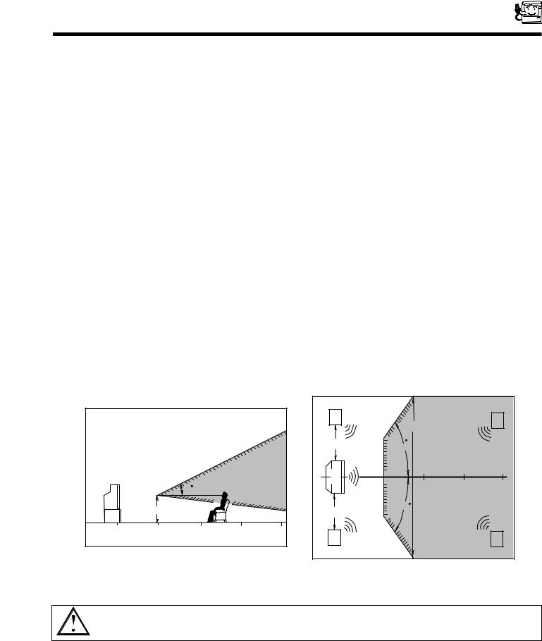
VIEWING
To view the color television screen at its best, test various locations in the room. The drawings below show several suggestions.
The best picture is seen by sitting directly in front of the color TV and about 6 to 9 feet from the screen. During daylight hours, reflections from outside light may appear on the screen. If so, drapes or screens can be used to reduce the reflection or the color TV can be located in a different section of the room.
If the color TV s audio output will be connected to a Hi-Fi system s external speakers, the best audio performance will be obtained by placing the speakers equidistant from each side of the receiver cabinet and as close as possible to the height of the picture screen center. For best stereo separation, place the external speakers at least four feet from the side of the color television, place the surround speakers to the side or behind the viewing area. Differences in room sizes and acoustical environments will require some experimentation with speaker placement for best performance.
|
|
|
|
|
|
|
|
|
|
||
|
|
|
|
|
|
|
|
|
|
|
|
|
|
|
|
|
|
|
|
|
|
|
|
|
|
|
|
|
|
CAUTION: The magnetic field of external speakers may cause the picture to distort if the speakers are placed too close to the color television. Move the speakers away from the color TV until there is no picture distortion.
7
HOOK-UP CABLES AND CONNECTORS
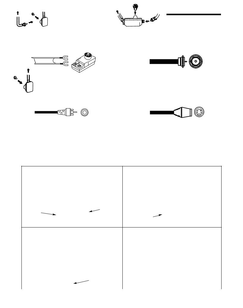
Most video/audio connections between components can be made with shielded video and audio cables that have phono connectors. For best performance, video cables should use 75-Ohm coaxial shielded wire. Cables can be purchased from most stores that sell audio/video products. Below are illustrations and names of common connectors. Before purchasing any cables, be sure of the output and input connector types required by the various components and the length of each cable.
300-Ohm Twin Lead Connector
This outdoor antenna cable must be connected to an antenna adapter (300-Ohm to 75-Ohm).
Phono Connector
Used on all standard video and audio cables which connect to inputs and outputs located on the television s rear jack panel and front control panel.
’’F’’ Type 75-Ohm Coaxial Antenna Connector
For connecting RF signals (antenna or cable TV) to the antenna jack on the television.
S-Video (Super Video) Connector
This connector is used on camcorders, VCRs, and laserdisc players with an S-Video feature in place of the standard video cable to produce a high quality picture.
Antenna Connections
These sets are equipped with one VHF/UHF antenna terminal. The VHF/UHF terminal can be used for normal TV, cable TV (CATV), a TV game, etc.
1. VHF (75-Ohm) antenna/CATV (Cable TV) |
3. When both VHF and UHF antennas are connected |
|||||
|
When using a 75-Ohm coaxial cable system, connect |
Attach an optional ANTENNA MIXER to the TV |
||||
|
the outdoor antenna or CATV coaxial cable to the ANT |
antenna terminal and connect the cables to the |
||||
|
A (75-Ohm) terminal. If you have a second antenna or |
ANTENNA MIXER. |
|
|||
|
cable TV system, connect the coaxial cable to the ANT |
|
VHF/UHF |
|||
|
B terminal. |
|
|
|
(Rear of TV set) |
|
|
|
|
|
|
||
|
|
To outdoor or CATV cable |
To UHF Antenna |
To outdoor |
||
|
|
|
VHF/UHF |
|
VHF Antenna |
|
|
|
|
|
(disconnect) |
|
|
|
75 Ohm |
|
|
|
|
|
|
|
|
VHF Adaptor |
|
|
|
|
Coaxial Cable |
|
|
|
|
|
|
|
|
|
|
|
|
|
|
|
|
|
ANTENNA |
|
|
|
|
|
|
|
|
|
|
|
|
|
MIXER |
|
2. VHF (300-Ohm) antenna/UHF antenna |
Notes: |
|||
When using a 300-Ohm twin lead from an outdoor |
1. |
If an outdoor antenna/CATV is used, disconnect the |
||
antenna disconnect the (VHF or UHF) indoor antenna |
|
indoor antenna. Ghosting and poor reception may |
||
leads from screws of the (VHF or UHF) adaptor and |
|
result if both the indoor and outdoor antennas/CATV |
||
connect outdoor (VHF or UHF) antenna leads to these |
|
are connected at the same time. |
||
screws of a (VHF of UHF) adaptor. |
|
|
||
|
To outdoor VHF |
2. |
Consult your dealer or service store for the |
|
|
or UHF Antenna |
|||
|
|
|
|
ANTENNA MIXER and (VHF or UHF) adaptor. |
|
(connect) |
|
|
|
|
VHF Adaptor |
|
|
|
|
|
|
3. The special converter (decoder) will be supplied by |
|
|
|
|
||
|
|
|
|
the cable company. |
|
|
|
|
|
|
|
|
8 |
|
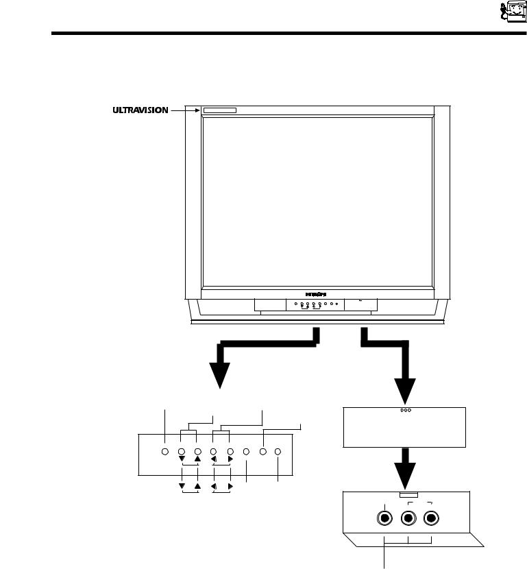
FRONT PANEL CONTROLS
32UX01S and |
|
36UX01S |
|
models only. |
|
POWER CH - CH + VOL - VOL + MENU INPUT |
PUSH |
CURSOR |
|
|
|
|
|
|
OPEN DOOR |
|
Power Button |
Channel Buttons Volume Buttons |
|
||||
PUSH |
||||||
|
|
|
|
MENU |
|
|
POWER CH - |
CH + VOL - |
VOL + INPUT |
|
|
|
|
|
|
EXIT |
MENU |
|
|
|
|
CURSOR |
|
|
|
|
|
|
CURSOR |
|
|
|
|
|
INPUT/ Infrared
EXIT Sensor
VIDEO
L/MONO R
Video 3 Input
A detailed explanation of the circled numbers is on page 10.
See page 22 and 24 for MENU, CURSOR, and EXIT button operations.
9

FRONT PANEL CONTROLS
POWER Button
Press this button to turn the TV on or off.
CHANNEL Selector
Press these buttons until the desired channel appears in the top right corner of the TV screen.
VOLUME Level
Press these buttons for your desired sound level. The volume level will be displayed on the TV screen.
INPUT/EXIT Button
Press this button to select the current antenna or VIDEO source. Your selection is shown in the top right corner of the screen. This button also serves as the EXIT button when in MENU mode.
NOTE: Your HITACHI TV will appear to be turned OFF if there is no video input when VIDEO Source is selected. Press the INPUT button until the normal broadcast picture appears. (See page 23) If the picture does not appear, the power is OFF.
MENU Button
This button allows you to enter the MENU, making it possible to set TV features to your preference with out using the remote.
REMOTE CONTROL INFRARED Sensor
Point your remote control at this area when selecting channels, adjusting volume, etc.
FRONT INPUT JACKS
Use these audio/video jacks for a quick hook-up to a comcorder or VCR to instantly view your favorite show or new recording. Press the INPUT button until VIDEO:3 appears in the top right corner of the TV screen. If you have mono sound, insert the audio cable into the left channel jack.
10
FRONT PANEL JACKS AND CONNECTIONS
The front panel jacks are provided as a convenience to allow you to easily connect a camcorder or VCR as shown in the following examples:
INPUT 3 |
|
INPUT 3 |
|
VIDEO L/MONO |
R |
VIDEO L/MONO |
R |
AUDIO |
|
AUDIO |
|
INPUT 3
VIDEO L/MONO R
 AUDIO
AUDIO 
NOTE: Completely insert connection cord plugs when connecting to front panel jacks. If you do not, the picture that is played back may be abnormal.
11
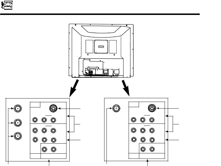
REAR PANEL JACKS
REAR PANEL OF TELEVISION
32/36UX01S |
|
|
|
|
ANT A |
|
|
|
|
INPUT 1 |
|
|
|
|
|
S-VIDEO |
|
||
|
|
|
||
VIDEO |
R |
L / (MONO) |
S-VIDEO |
|
INPUT |
||||
TO CONVERTER |
|
AUDIO |
||
|
|
|
||
VIDEO |
R |
L / (MONO) |
||
ANT B |
|
AUDIO |
INPUT |
|
|
|
|
TERMINALS |
|
Y |
P B |
PR |
|
|
|
|
COMPO- |
||
|
|
NENT |
||
|
|
VIDEO |
||
|
R |
L |
Y-PB-PR |
|
|
|
|
INPUTS |
|
INPUT 2 AUDIO TO HI-FI |
|
|||
|
|
|
||
|
|
|||
VHF/UHF
ANTENNA TERMINALS AUDIO TO HI-FI OUTPUT TERMINALS
|
32/36GX01B |
|
||
VHF/UHF |
|
|
|
|
INPUT 1 |
|
|
|
|
|
S-VIDEO |
|
||
|
|
|
||
VIDEO |
R |
L / (MONO) |
S-VIDEO |
|
INPUT |
||||
|
|
|
||
|
|
AUDIO |
|
|
VIDEO |
R |
L / (MONO) |
||
|
|
AUDIO |
INPUT |
|
|
|
|
TERMINALS |
|
Y |
P B |
PR |
|
|
|
|
COMPO- |
||
|
|
NENT |
||
|
|
VIDEO |
||
|
R |
L |
Y-PB-PR |
|
|
|
|
INPUTS |
|
INPUT 2 AUDIO TO HI-FI |
|
|||
|
|
|
||
|
|
|||
VHF/UHF
ANTENNA TERMINAL AUDIO TO HI-FI OUTPUT TERMINALS
Antenna Inputs
32GX01B and 36GX01B models
The VHF/UHF terminal can be used for Normal TV, Cable TV (CATV), video games, etc.
32UX01S and 36UX01S models
The remote control allows you to switch between two separate 75-Ohm RF antenna inputs, ANT A and ANT B. ANT A input can be displayed as a main picture or sub-picture. ANT B can only be displayed as a main picture. (ANT B cannot be displayed as a sub-picture.) The antenna output labeled TO CONVERTER allows the ANT A connection to pass directly to a different source such as a cable box.
Audio/Video Inputs 1, 2
The INPUT button will step through each video source and antenna source input each time it is pressed. Use the audio and video inputs to connect external devices, such as VCRs, camcorders, laserdisc players, etc. (If you have mono sound, insert the audio cable into the left channel jack.)
Y-PBPR Input
This input provides Y-PBPR jacks for connecting equipment with this capability, such as a DVD Player. This input can receive 480i signal only.
Audio to HI-FI
These jacks provide variable audio output to a separate stereo amplifier. With this connection, the audio to the stereo can be controlled by the television s main volume. Use these jacks for the SURROUND Left and Right channels. (See page 19)
S-Video
Inputs 1 provide S-Video (Super Video) jacks for connecting equipment with S-Video output capability.
12
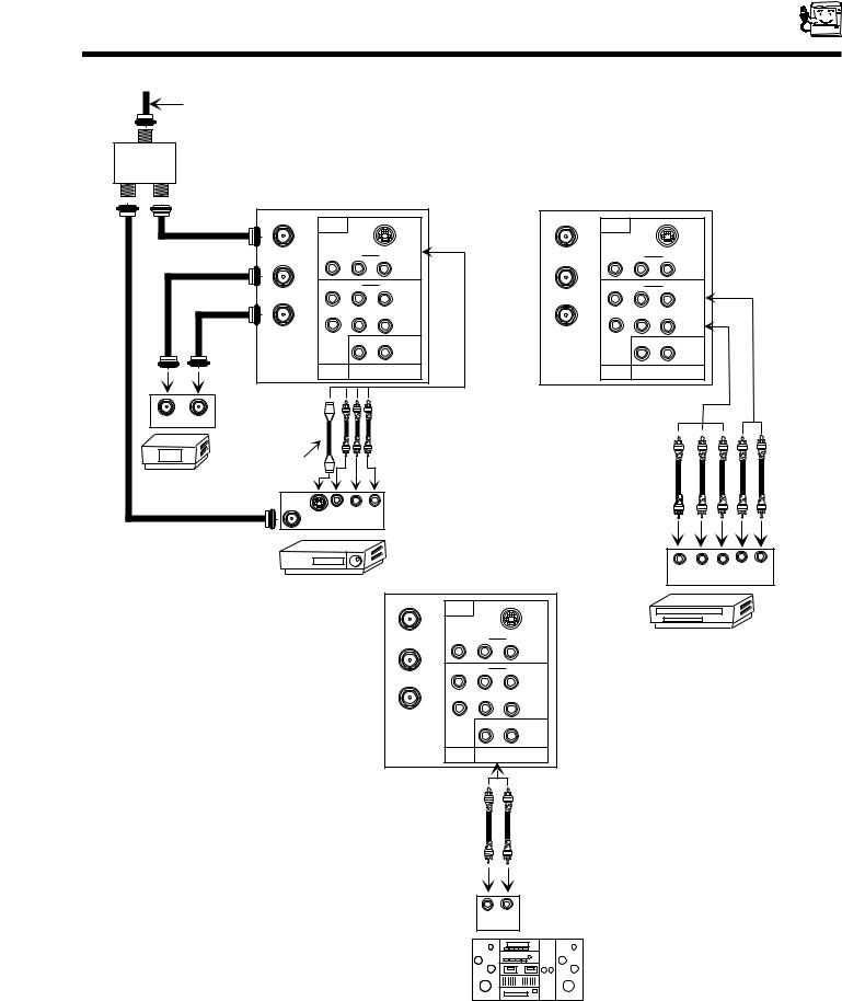
REAR PANEL CONNECTIONS (32UX01S and 36UX01S)
Outside antenna or cable TV coaxial cable
 2-Way signal splitter
|
ANT A |
|
|
ANT A |
|
|
|
INPUT 1 |
|
|
INPUT 1 |
|
|
|
|
S-VIDEO |
|
|
S-VIDEO |
|
|
VIDEO |
R |
L / (MONO) |
VIDEO |
R |
L / (MONO) |
|
TO CONVERTER |
|
AUDIO |
TO CONVERTER |
|
AUDIO |
|
|
|
|
|
||
|
VIDEO |
R |
L / (MONO) |
VIDEO |
R |
L / (MONO) |
|
ANT B |
|
AUDIO |
ANT B |
|
AUDIO |
|
Y |
P B |
PR |
Y |
P B |
PR |
|
|
|
COMPO- |
|
|
COMPO- |
|
|
|
NENT |
|
|
NENT |
|
|
|
VIDEO |
|
|
VIDEO |
|
|
R |
L |
|
R |
L |
|
INPUT 2 |
AUDIO TO HI-FI |
INPUT 2 |
AUDIO TO HI-FI |
||
INPUT |
OUTPUT |
|
|
|
|
|
|
Optional, see tips |
|
|
|
|
|
|
on page 15 |
|
|
|
|
|
Cable TV Box |
|
|
|
|
|
|
|
ANT |
|
|
|
|
|
|
IN |
|
|
|
|
|
|
S-VHS V |
L |
R |
|
|
|
|
OUTPUT |
|
|
|
|
|
VCR #1
L R
Y PB PR OUTPUT
ANT A |
|
|
INPUT 1 |
|
|
|
S-VIDEO |
|
VIDEO |
R |
L / (MONO) |
TO CONVERTER |
|
AUDIO |
|
|
|
VIDEO |
R |
L / (MONO) |
ANT B |
|
AUDIO |
Y |
P B |
P R |
|
|
COMPO- |
|
|
NENT |
|
|
VIDEO |
|
R |
L |
DVD Player, Laserdisc player, etc.
INPUT 2 AUDIO TO HI-FI
L R
INPUT
Stereo System Amplifier
Typical full feature setup. Follow connections that pertain to your personal entertainment system.
13
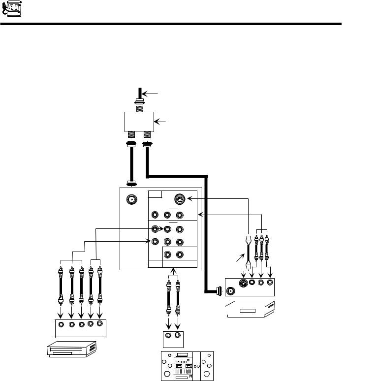
REAR PANEL CONNECTIONS (32GX01B AND 36GX01B)
Outside antenna or cable TV coaxial cable
2-Way signal splitter
L R
Y PB PR OUTPUT
DVD Player, Laserdisc player, etc.
VHF/UHF |
|
|
|
|
|
|
INPUT 1 |
|
|
|
|
|
|
|
S-VIDEO |
|
|
|
|
|
VIDEO |
R |
L / (MONO) |
|
|
|
|
|
|
AUDIO |
|
|
|
|
VIDEO |
R |
L / (MONO) |
|
|
|
|
|
|
AUDIO |
|
|
|
|
Y |
P B |
PR |
|
|
|
|
|
|
COMPO- |
|
|
|
|
|
|
NENT |
|
|
|
|
|
|
VIDEO |
|
|
|
|
|
R |
L |
|
|
|
|
INPUT 2 |
AUDIO TO HI-FI |
Optional, see tips |
|
|
|
|
|
|
|
on page 15 |
|
|
|
|
|
|
ANT |
|
|
|
|
|
|
IN |
V |
L |
R |
|
|
|
S-VHS |
|||
|
|
|
|
OUTPUT |
|
|
VCR #1 

L R
INPUT
Stereo System Amplifier
Typical full feature setup. Follow connections that pertain to your personal entertainment system.
14
TIPS ON REAR PANEL CONNECTIONS
The S-Video connections are provided for high performance laserdisc players, VCRs etc. that have this feature. Use these connections in place of the standard video connection if your device has this feature.
COMPONENT: Y-PBPR connections are provided for high performance components, such as DVD players. Use these connections in place of the standard video connection if your device has this feature.
When using the Y-PBPR input jacks, connect your components audio output to the TV s Input 2 Left and Right Audio input jacks.
If your device has only one audio output (mono sound), connect it to the left audio jack on the television.
Refer to the operating guide of your other electronic equipment for additional information on connecting your hook-up cables.
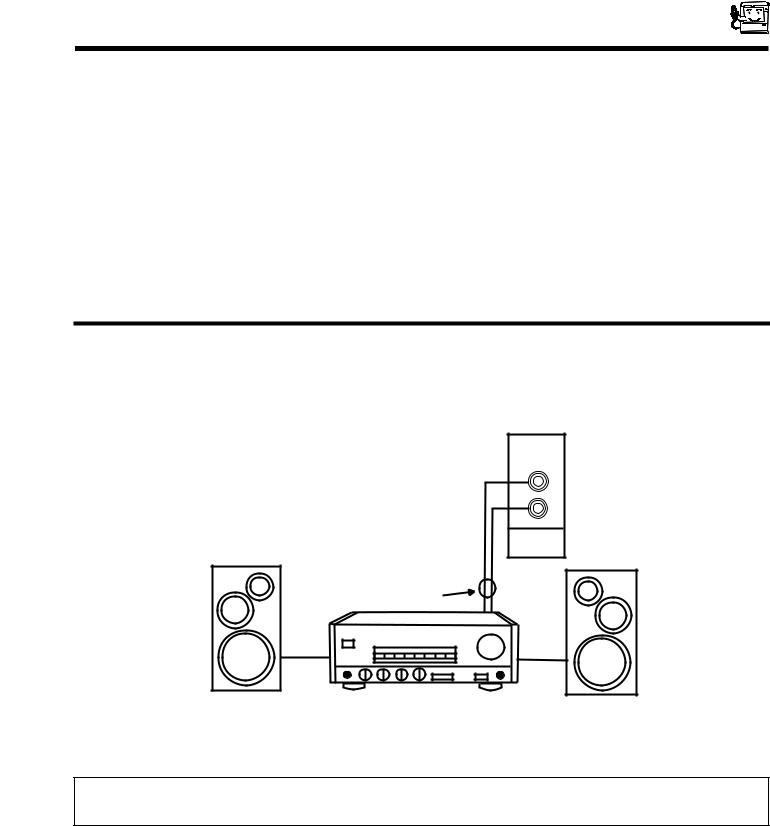
EXTERNAL CONNECTIONS
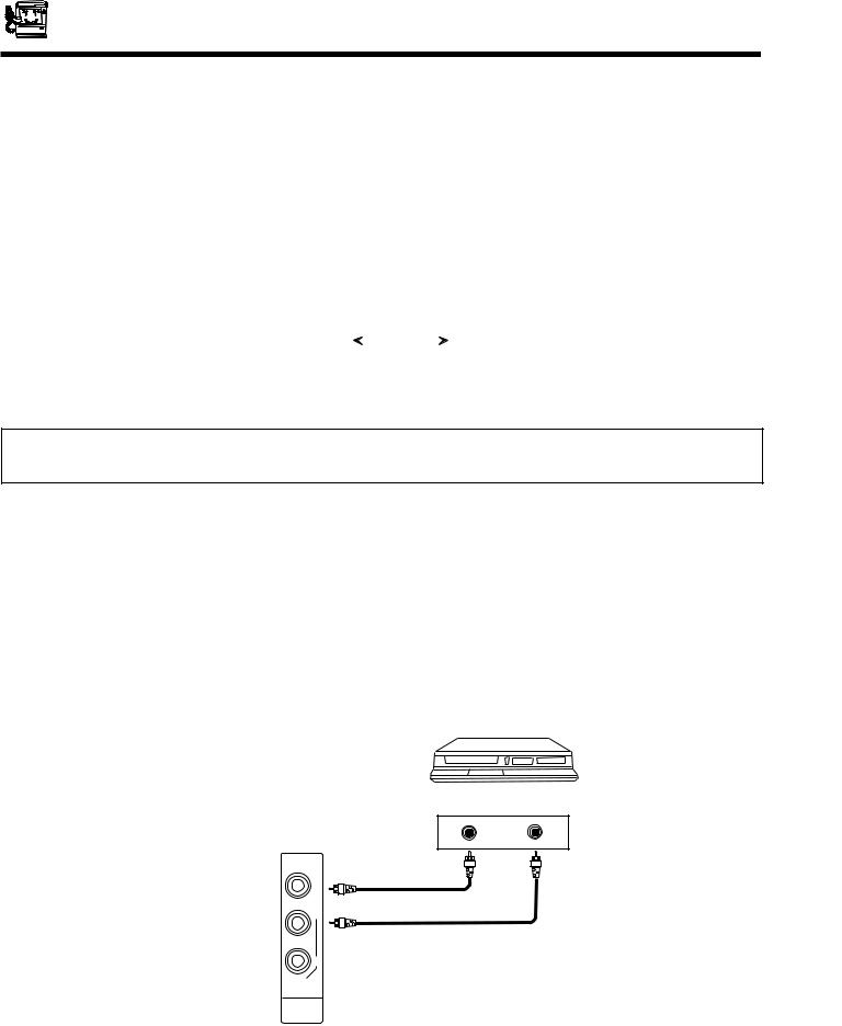
CONNECTING EXTERNAL AUDIO AMPLIFIER
To control the audio level of an external audio amplifier with the remote control, connect the system as shown below.
|
|
|
|
|
|
|
|
|
|
|
NOTE: To prevent damage to the speaker and distorted sound, set the volume control of the audio amplifier lower and adjust the sound using the remote control of the TV set.
15
CONNECTING EXTERNAL VIDEO SOURCES
The exact arrangement you use to connect the VCR, camcorder, laserdisc player to your TV set is dependent on the model and features of each component. Check the owner s manual of each component for the location of video and audio inputs and outputs.
The following connection diagrams are offered as suggestions. However, you may need to modify them to accommodate your particular assortment of components and features. For best performance, video and audio cables should be made from coaxial shielded wire.
Before Operating External Video Source
The input mode is changed every time the INPUT button is pressed as shown below. Connect an external source to the INPUT terminal, then press the INPUT button as necessary to view the input source. (See page 23.)
|
|
|
|
|
|
|
|
|
|
|
|
NOTE: When the TV is set to VIDEO and a video signal is not received from the VIDEO INPUT JACK on the jack panel of the TV (i.e., VCR/laserdisc player, etc. is not connected or the video device is OFF), the screen will be gray-blue.
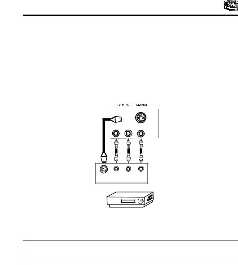
CONNECTING A MONAURAL AUDIO VCR OR LASERDISC PLAYER
1.Connect the cable from the VIDEO OUT of the VCR or the laserdisc player to the INPUT (VIDEO) jack on the TV set below.
2.Connect the cable from the AUDIO OUT of the VCR or the laserdisc player to the INPUT (MONO)/L(AUDIO) jack.
3.Press the INPUT button to view the program from the VCR or the laserdisc player. The VIDEO mode disappears automatically after approximately eight seconds.
4.Press the INPUT button to return to the previous channel.
V CR
TV INPUT
TERMINAL
VIDEO OUT AUDIO OUT
VIDEO
(MONO)
L
R
AUDIO
INPUT
16
CONNECTING EXTERNAL VIDEO SOURCES
CONNECTING A STEREO VCR OR STEREO LASERDISC PLAYER
1.Connect the cable from the VIDEO OUT of the VCR of the laserdisc player to the INPUT (VIDEO) jack on the TV set below.
2.Connect the cable from the AUDIO OUT R of the VCR or the laserdisc player to the INPUT(AUDIO/R) jack.
3.Connect the cable from the AUDIO OUT L of the VCR or the laserdisc player to the INPUT(AUDIO/L) jack.
4.Press the INPUT button to view the program from the VCR or laserdisc player. The mode VIDEO disappears automatically after approximately eight seconds.
5.Press the INPUT button to return to the previous source.
INPUT 1
S-VIDEO
VIDEO |
R |
|
L / (MONO) |
|
AUDIO
S-VHS |
V |
R |
L |
OUTPUT
BACK OF VCR
HITACHI MODEL or similar model
NOTE: Completely insert the connection cord plugs when connecting to rear panel jacks. The picture that is played back will be abnormal if the connection is loose.
If you have an S-VHS VCR, use the S-INPUT cable in place of the standard video cable.
17

CONNECTING EXTERNAL VIDEO SOURCES
CONNECTING A STEREO LASERDISC PLAYER OR DVD PLAYER TO INPUT 2.
1.Connect the cable from the Y OUT of the Laserdisc or the DVD player to the INPUT 2 (Y) jack as shown below.
2.Connect the cable from the PB OUT of the Laserdisc or the DVD player to the INPUT 2 (PB) jack, as shown below.
3.Connect the cable from the PR OUT of the Laserdisc or the DVD player to the INPUT 2 (PR) jack, as shown below.
4.Connect the cable from the AUDIO OUT R of the Laserdisc or DVD player to the INPUT 2 (AUDIO/R) jack.
5.Connect the cable from the AUDIO OUT L of the Laserdisc or DVD player to the INPUT 2 (AUDIO/L) jack.
6. Press the INPUT button until Y-PBPR appears, to view the program from the Laserdisc or DVD player. The mode Y-PBPR disappears automatically after approximately eight seconds.
7. Press the INPUT button to return to the previous source.
32/36UX01S |
|
|
ANT A |
|
|
INPUT 1 |
|
|
|
S-VIDEO |
|
VIDEO |
R |
L / (MONO) |
TO CONVERTER |
|
AUDIO |
|
|
|
VIDEO |
R |
L / (MONO) |
ANT B |
|
AUDIO |
Y |
P B |
P R |
|
|
COMPO- |
|
|
NENT |
|
|
VIDEO |
|
R |
L |
INPUT 2 AUDIO TO HI-FI |
||
32/36GX01B |
|
|
VHF/UHF |
|
|
INPUT 1 |
|
|
|
S-VIDEO |
|
VIDEO |
R |
L / (MONO) |
|
|
AUDIO |
VIDEO |
R |
L / (MONO) |
|
|
AUDIO |
Y |
P B |
PR |
|
|
COMPO- |
|
|
NENT |
|
|
VIDEO |
|
R |
L |
INPUT 2 AUDIO TO HI-FI |
||
YPB PR L R OUTPUT
Y PB PR L R
OUTPUT
BACK OF DVD PLAYER |
BACK OF DVD PLAYER |
NOTE: Completely insert the cable connection when connecting to rear panel jacks. The picture that is played back will be abnormal if the connection is loose.
If you have a COMPONENT DVD or LASERDISC, use the COMPONENT connections in place of the standard or S-Video connection.
Y-PBPR can receive 480i signal only.
See Page 14 for TIPS ON REAR PANEL CONNECTIONS.
18
 Loading...