


SERIES D
INSTRUCTIONS-PARTS
LIST
307–830
This
manual contains important
warnings and information.
READ AND KEEP FOR REFERENCE.
INSTRUCTIONS
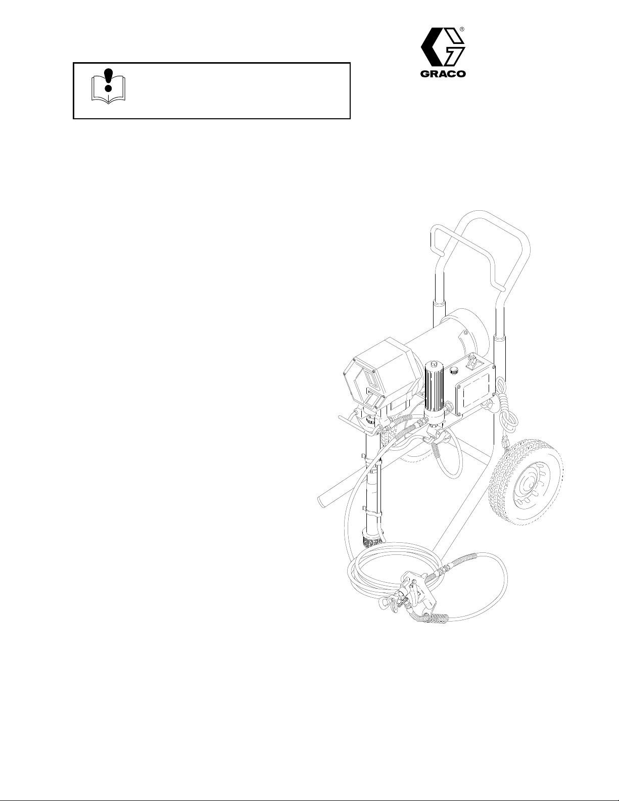
EM590
2750 psi (190 bar, 19 MPa) Maximum Working Pressure
Model
Basic
Model
Same
3 ft (0.9 m) whip hose and spray gun with RAC IV
DripLess T
220–856, Series D
sprayer on Upright cart without hose or gun
231–590, Series A
as 220–856 and includes 50 ft (15.1 m) hose,
ip Guard and 517 size SwitchT
Airless Paint Sprayer
ip
First
choice when
quality counts.
Supersedes Rev
Rev. F
. E
GRACO INC. P.O. BOX 1441
http://www.graco.com
COPYRIGHT
Graco
Inc. is registered to I.S. EN ISO 9001
MINNEAPOLIS, MN
1987, GRACO INC.
01744C
55440–1441
Table
of Contents
Warnings 2.
Setup 5
Startup
Maintenance
Flushing 9
Application
Troubleshooting 11
Motor
Displacement
Connecting
. . . . . . . . . . . . . . . . . . . . . . . . . . . . . . . . . . . . .
. . . . . . . . . . . . . . . . . . . . . . . . . . . . . . . . . . . . . . . . .
7. . . . . . . . . . . . . . . . . . . . . . . . . . . . . . . . . . . . . . .
8. . . . . . . . . . . . . . . . . . . . . . . . . . . . . . . . . .
. . . . . . . . . . . . . . . . . . . . . . . . . . . . . . . . . . . . . .
Methods
Brush Replacement
Pump
Rod and Bearing Housing
. . . . . . . . . . . . . . . . . . . . . . . . . .
. . . . . . . . . . . . . . . . . . . . . . . . . . . . . . .
. . . . . . . . . . . . . . . . . . . . . . . . . .
. . . . . . . . . . . . . . . . . . . . .
. . . . . . . . . .
10.
13.
14.
15.
Symbols
Warning Symbol
WARNING
This
symbol alerts you to the possibility of serious
injury or death if you do not follow the instructions.
WARNING
Drive
Housing
Motor 17
. . . . . . . . . . . . . . . . . . . . . . . . . . . . . . . . . . . . . . . .
Pressure
Pressure
Parts
Parts
Technical
Graco
Accessories 27
Graco Warranty 28.
Control
Control Adjustment
– Pressure Control
– Upright Sprayer
Data
Phone Number
. . . . . . . . . . . . . . . . . . . . . . . . . . . . . . .
. . . . . . . . . . . . . . . . . . . . . . . . . . . . .
. . . . . . . . . . . . . . . . . .
. . . . . . . . . . . . . . . . . . . . . .
. . . . . . . . . . . . . . . . . . . . . . .
. . . . . . . . . . . . . . . . . . . . . . . . . . . . . . .
. . . . . . . . . . . . . . . . . . . . . . . . .
. . . . . . . . . . . . . . . . . . . . . . . . . . . . . . . . . .
. . . . . . . . . . . . . . . . . . . . . . . . . . . . . .
16.
19.
21.
23.
25.
27.
27.
Caution Symbol
CAUTION
This
symbol alerts you to the possibility of damage to
or destruction of equipment if you do not follow the
instructions.
FIRE AND EXPLOSION HAZARD
Improper
result in a fire or explosion and serious injury
grounding, poor ventilation, open flames or sparks can cause a hazardous condition and
.
If there is any static sparking or you feel an electric shock while using this equipment,
ing immediately. Do not use the equipment until you identify and correct the problem.
Provide fresh air ventilation to avoid the buildup of flammable fumes from solvents or the fluid
being sprayed.
Keep the spray area free of debris, including solvent, rags, and gasoline.
Electrically disconnect all equipment in the spray area.
Extinguish all open flames or pilot lights in the spray area.
Do not smoke in the spray area.
Do not turn on or of
Do not operate a gasoline engine in the spray area.
Use only with a grounded outlet that matches the grounded plug of this equipment.
f any light switch in the spray area while operating or if fumes are present.
stop spray-
WARNING
INJECTION HAZARD
Spray
from the gun, leaks or ruptured components can inject fluid into your body and cause extremely
serious injury, including the need for amputation. Fluid splashed in the eyes or on the skin can also
cause serious injury
Fluid injected into the skin is a serious injury
injury
. Get immediate medical attention.
Do not point the gun at anyone or at any part of the body
Do not put your hand or fingers over the spray tip.
Do not stop or deflect leaks with your hand, body
Do not “blow back” fluid; this is not an air spray system.
Always have the tip guard and the trigger guard on the gun when spraying.
Check the gun dif
Be sure the gun trigger safety operates before spraying.
Lock the gun trigger safety when you stop spraying.
.
fuser operation weekly
. The injury may look like just a cut, but it is a serious
.
, glove or rag.
. Refer to the gun manual.
Follow the
checking or servicing the equipment.
T
ighten all fluid connections before operating the equipment.
Check the hoses, tubes, and couplings daily
repair high pressure couplings; you must replace the entire hose.
Fluid hoses must have spring guards on both ends, to help protect them from rupture caused by
kinks or bends near the couplings.
Pressure Relief Procedure
on page 1
1 if the spray tip clogs and before cleaning,
. Replace worn or damaged parts immediately
TOXIC FLUID HAZARD
Hazardous
inhaled, or swallowed.
Know the specific hazards of the fluid you are using.
Store hazardous fluid in an approved container
state and national guidelines.
Always wear protective eyewear
solvent manufacturer
fluid or toxic fumes can cause serious injury or death if splashed in the eyes or on the skin,
. Dispose of hazardous fluid according to all local,
, gloves, clothing and respirator as recommended by the fluid and
.
MOVING PARTS HAZARD
. Do not
Moving
parts can pinch or amputate your fingers.
Keep clear of all moving parts when starting or operating the pump.
Before servicing the equipment, follow the
equipment from starting unexpectedly
Pressure Relief Procedure
.
on page 1
1 to prevent the
WARNING
EQUIPMENT MISUSE HAZARD
INSTRUCTIONS
Equipment
This equipment is for professional use only
Read all instruction manuals, tags, and labels before operating the equipment.
Use the equipment only for its intended purpose. If you are not sure, call your distributor
Do not alter or modify this equipment. Use only genuine Graco parts.
Check equipment daily
Do not exceed the maximum working pressure of the lowest rated system component. Refer to the
T
Use fluids and solvents which are compatible with the equipment wetted parts. Refer to the
nical Data
Do not use 1,1,1–trichloroethane, methylene chloride, other halogenated hydrocarbon solvents or
misuse can cause the equipment to rupture or malfunction and result in serious injury
.
echnical Data
. Repair or replace worn or damaged parts immediately
on page 27 for the maximum working pressure of this equipment.
.
section of all equipment manuals. Read the fluid and solvent manufacturer’s warnings.
.
fluids containing such solvents in pressurized aluminum equipment. Such use could result in a
chemical reaction, with the possibility of explosion.
Do not use hoses to pull equipment.
Route hoses away from traffic areas, sharp edges, moving parts, and hot surfaces. Do not expose
Graco hoses to temperatures above 82C (180F) or below –40C (–40
F).
.
Tech-
Do not lift pressurized equipment.
Comply with all applicable local, state, and national fire, electrical, and safety regulations.
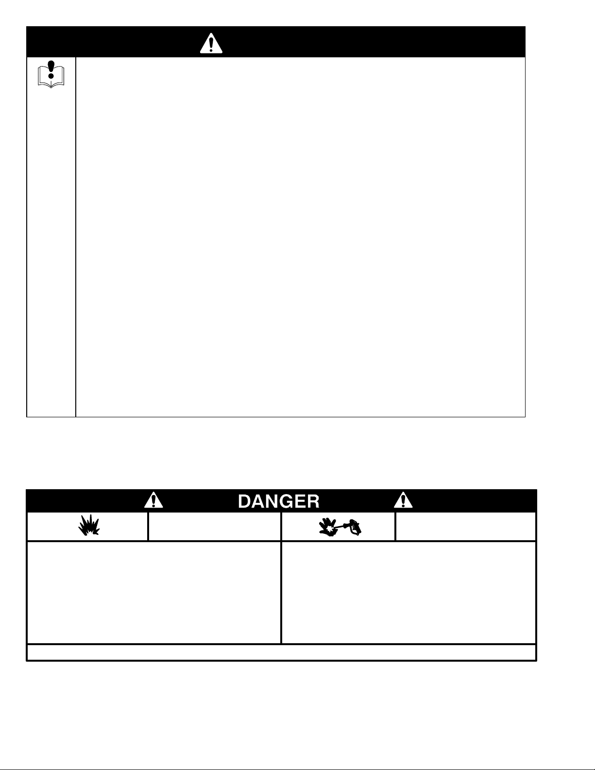
NOTE: This
is an example of the DANGER label on
your sprayer
. This label is available in other
languages, free of charge. See page 27 to order
FIRE
AND
EXPLOSION HAZARD
Spray
painting, flushing or cleaning equipment with flammable liquids in
confined
Use outdoors or in extremely well ventilated areas. Ground equipment,
hoses,
A
cloths,
arcs
switches on and of
Failure to follow this warning can result in death or serious injury
areas can result in fire or explosion.
containers and objects being sprayed.
void all ignition sources such as static electricity from plastic drop
open flames
from connecting or disconnecting power cords or turning light
such as pilot lights, hot objects such as cigarettes,
f.
.
READ AND UNDERSTAND ALL LABELS AND INSTRUCTION MANUALS BEFORE USE
.
SKIN INJECTION
HAZARD
Liquids
can be injected into the body by high pressure airless spray or
leaks
– especially hose leaks.
Keep body clear of the nozzle. Never stop leaks with any part of the
body
. Drain all pressure before removing parts.A
ing of gun by always setting safety latch when not spraying.
Never spray without a tip guard.
In case of accidental skin injection, seek immediate
“Surgical T
Failure to follow this warning can result in amputation or serious injury
reatment”.
void accidental trigger
-
.
4 307-830
Setup
WARNING
T
o reduce the risk of serious bodily injury caused
by static sparking, fluid injection or over–pressuri
zation and rupture of the hose or gun, all hoses
must be electrically conductive, the gun must have
a tip guard, and each part must be rated for at least
2750 psi (190 bar
, 19 MPa)
Working Pressure.
CAUTION
T
o avoid damaging the pressure control, which may
result in poor equipment performance and compo
nent damage:
1.
Always use grounded, flexible spray hose (85) at
least 50 ft (15 m) long.
2.
Never use a wire braid hose as it is too rigid to
act as a pulsation dampener
3.
Never install any shutof
(15) and the main hose. See Fig. 1.
.
f device between the filter
WARNING
1. Connect the hoses and gun to the sprayer.
a 1/4 in. ID, 50 ft (15 m) long (minimum) main
hose (85). For more flexible gun movement, install
-
-
a 3/16 in. ID, 3 ft (0.9 m) hose (86) between the
main hose and the gun (87). Don’t use thread
sealant, and don’t install the spray tip yet!
2. Fill the packing nut/wet-cup (221)
Throat Seal Liquid (TSL), supplied.
3.
Check the electrical service.
a.
Electrical requirements: 120 V
15A (minimum).
b.
Use a grounded electrical outlet located at
least 20 ft (6 m) from the spray area.
c.
Do not remove the grounding prong of the
power supply cord, and do not use an
ungrounded adapter
d.
Extension cord specifications: 15A, 3 wires,
grounding type. Note that long lengths reduce
sprayer performance. A maximum extension
cord length of 200 ft (60 m) is recommended.
.
1/3 full with
AC, 60 Hz,
Use
FIRE AND EXPLOSION HAZARD
Proper electrical grounding is essential
to reduce the risk of fire or explosion
which can result in serious bodily injury
and property damage. See the warning
section
ARD
grounding instructions.
FIRE OR EXPLOSION HAZ
on page 2 for more detailed
-
4. Flush the pump
pump parts after factory testing. See
page 9.
5.
Prepare the paint.
the paint thoroughly
nylon mesh bag to remove particles that could clog
the filter
, if used, or the spray tip.
to remove the oil left in to protect
Flushing
Remove any paint skin. Stir
. Strain the paint through a fine
on
307-830 5
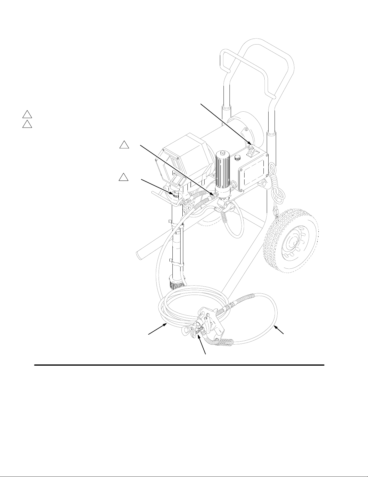
Keep
1/3 full with TSL at all times
Never install any shutof
f device here
Setup
114
15b
221
Fig.
1
6 307-830
85
87
86
01744C
Use
this procedure to help you start and operate the
sprayer properly and safely
.
Startup
5. Check all fluid connections for leaks
the
tightening connections.
Pressure Relief Procedure
. Follow
on page 1
1 before
WARNING
INJECTION HAZARD
T
o reduce the risk of serious bodily
injury
, follow the
dure W
ing or repairing any part of the spray system.
NOTE:
See page 9.
NOTE:
1. Turn the pressure adjusting knob (A) fully
2. Put the intake tube (3) in the fluid container.
3.
Flush the sprayer if this is a first-time startup.
See Fig. 3 except where noted.
counterclockwise to minimum pressure.
Plug in the sprayer
arning
Pressure Relief Proce
on page 1
.
1 before check
6. Install the spray tip and tip guard.
trigger safety latch. Install the spray tip according
to the instructions supplied with it.
-
-
7. Adjust the spray pattern.
Increase the pressure slowly just until spray
a.
from the gun is completely atomized. Use the
lowest pressure needed to get the desired
results. This reduces overspray and fogging,
decreases tip wear and extends sprayer life.
b.
If more coverage is needed, use a larger tip
rather than increasing the pressure.
c. T
est the spray pattern. Adjust the spray tip
pattern according to the instructions supplied
with the gun or tip.
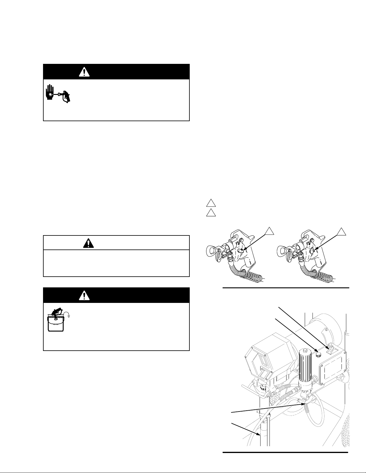
Trigger
safety latch shown engaged (SAFE)
T
rigger safety latch shown disengaged (OFF SAFE)
Engage the
CAUTION
Do not run the pump without fluid in it for more than
30 seconds to avoid damage to the displacement
pump packings.
WARNING
FIRE AND EXPLOSION HAZARD
T
o reduce the risk of static sparking and
splashing when flushing, always remove
the spray tip from the gun and hold a
metal part of the gun firmly to the side of grounded
metal pail.
4.
Prime the pump.
a. Open
b. Disengage
the
pressure drain valve (44). T
sprayer switch (105a). Slowly turn the pressure
adjusting knob (A) clockwise until the sprayer
starts.
When fluid comes from the
the trigger safety latch. See Fig. 2.
Holding a metal part of the gun firmly against a
grounded metal pail, trigger the gun until all air
is forced out of the system and the paint flows
freely from the gun.
urn on the
valve close it.
Fig. 2
105a
A
44
3
c.
Release the trigger and engage the trigger
safety latch.
Fig.
3
01745C
Maintenance
WARNING
INJECTION HAZARD
T
o reduce the risk of serious bodily
injury
, follow the
dure W
ing or repairing any part of the spray system.
arning
Pressure Relief Proce
on page 1
1 before check
Cleaning a Clogged Tip
WARNING
To
reduce the risk of serious bodily injury from from
fluid injection:
NEVER operate the spray gun with the tip guard
removed.
DO NOT hold your hand, body
the spray tip when cleaning or checking for a clog.
Always point the gun toward the ground or into a
pail.
, or a rag in front of
5. For very short shutoff periods,
tube in the paint, relieve pressure, and clean the
spray tip.
-
-
6. Flush the sprayer at the end of each work day
and fill it with mineral spirits to help prevent pump
corrosion and freezing. See page 9.
leave the suction
CAUTION
T
o prevent pump corrosion, and to reduce the
chance of fluid freezing in the pump or pressure
control in cold weather
type of paint in the sprayer when it is not in use.
Freezing can seriously damage the sprayer or result
in a loss of pressure or stalling.
7. Coil the hose and hang it on the hose rack
when storing it, even for overnight, to help protect
the hose from kinking, abrasion, coupling damage,
etc.
, never leave water or any
DO NOT try to “blow back” paint; this is NOT an air
spray sprayer
1.
Clean the front of the tip frequently
Pressure Relief Procedure
2.
Follow the cleaning instructions given in your
separate gun or spray tip instruction manual.
.
. Follow the
, page 1
1, first.
Shutdown and Care
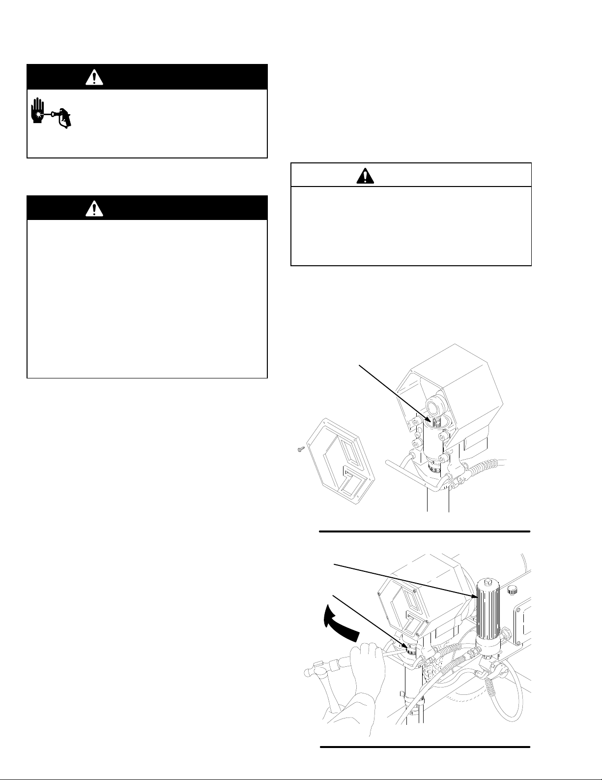
1. Keep the packing nut/wet-cup (221) 1/3 full of
TSL
(Throat Seal Liquid, supplied) at all times to
help prevent fluid buildup on the piston rod and
premature wear of packings. Follow the
Relief Procedure
2. Keep the packing nut/wet-cup just tight
enough to stop leakage.
ing causes binding and excessive packing wear
Follow the
Then use a round punch or brass rod and light
hammer to adjust the nut.
Pressure Relief Procedure
, page 1
1, before adding TSL.
See Fig. 5. Overtighten
Pressure
, page 1
1.
A
Fig. 4
15
-
.
221
7460A
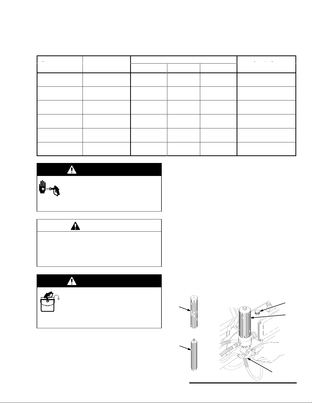
3. Clean the fluid filter (15) often
the sprayer is stored. Follow the
Procedure
4. Lubricate the bearing housing (A)
100 hours of operation
Relief Procedure
cover
non-detergent oil. See Fig. 4.
, page 1
. Fill the bearing housing cavity with SAE 10
1, before cleaning the filter
. Follow the
, page 11. Remove the front
, and whenever
Pressure Relief
after every
Pressure
.
Fig. 5
01748C
Flushing
y
ypy
NOTE:
Several flushes may be required to clean the system and prepare it for the next fluid or storage. Use this
chart to determine the required flushes and use the procedure below for flushing.
*Use this category for flushing a brand new sprayer and flushing after storage.
System
fluid in it:
*Oil-based solvent
or paint
Oil-based solvent or
paint
Oil-based solvent or
paint
W
based paint
W
based paint
W
based paint
has this
ater or water-
ater or water-
ater or water-
Next fluid to be
sprayed:
Oil-based paint –
new color
W
ater-based paint
Prepare for storage
W
ater–based
paint – new color
Oil-based paint
Prepare for storage
Flushing order
Flush 1 Flush 2 Flush 3
Mineral spirits
Mineral spirits
Mineral spirits
W
arm soapy
water
W
arm soapy
water
W
arm soapy
water
none none
W
arm soapy
water
none none
Clean water
Clean water
Clean water
4.
Remove the spray tip from the gun.
Clean water
none
Mineral spirits
Mineral spirits
WARNING
5.
INJECTION
T
o reduce the risk of serious bodily
injury
, follow the
dure W
HAZARD
arning
Pressure Relief Proce
on page 1
1 before check
ing or repairing any part of the spray system.
CAUTION
-
-
Put the suction tube into a grounded metal pail
with 1/2 gallon of compatible solvent.
6.
Start the sprayer
the sprayer as you start to flush, trigger the gun
into another container until the next fluid appears,
then trigger the gun back into the fluid you are
pumping. Circulate the flushing fluid a couple of
minutes to thoroughly clean the system.
Before you spray or store
sprayer:
Prime with oil
Prime with water
Relieve pressure
Leave drain valve open
Prime with water
Prime with oil
Relieve pressure
Leave drain valve open
. See page 7. T
o save the fluid in
NEVER allow water or water–base material to freeze
in the pressure control. Doing so prevents the
sprayer from being started and causes serious
damage to the pressure control. Pump the water out
with mineral spirits.
WARNING
FIRE AND EXPLOSION HAZARD
T
o reduce the risk of static sparking and
splashing when flushing, always remove
the spray tip from the gun and hold a
metal part of the gun firmly to the side of grounded
metal pail.
1.
Relieve pressure. Engage the trigger safety latch.
2.
Remove the filter bowl (B) and screen (C). Rein
stall the bowl and support (D) only
screen separately
urn the pressure adjusting knob (A) fully counter
3. T
.
clockwise to the minimum pressure.
. Clean the
7.
Raise the suction tube and trigger the gun to force
solvent from the hose. Do not run the pump dry for
more than 30 seconds to avoid damaging the
pump packings! Relieve pressure.
8.
Remove the suction tube and clean separately
9.
Install the filter screen. Hand tighten the bowl.
.
A
C
B
D
-
-
Fig. 6
44
01749A
307-830 9
 Loading...