


Model
Modèle
Modelo
M 12VC • M 12SC KM 12VC • KM 12SC
Router
Toupie
Fresadora
3/8
1/4
3/8
1/2
M12VC
SAFETY INSTRUCTIONS AND INSTRUCTION MANUAL
 WARNING
IMPROPER OR UNSAFE use of this power tool can result in death or serious bodily injury!
This manual contains important information about product safety. Please read and understand this manual BEFORE operating the power tool. Please keep this manual available for other users and owners before they use the power tool. This manual should be stored in safe place.
INSTRUCTIONS DE SECURITE ET MODE D’EMPLOI
 AVERTISSEMENT
Une utilisation INCORRECTE OU DANGEREUSE de cet outil motorisé peut entraîner la mort ou de sérieuses blessures corporelles !
Ce mode d’emploi contient d’importantes informations à propos de la sécurité de ce produit. Prière de lire et de comprendre ce mode d’emploi AVANT d’utiliser l’outil motorisé. Garder ce mode d’emploi à la disponibilité des autres utilisateurs et propriétaires avant qu’ils utilisent l’outil motorisé. Ce mode d’emploi doit être conservé dans un endroit sûr.
INSTRUCCIONES DE SEGURIDAD Y MANUAL DE INSTRUCCIONES
 ADVERTENCIA
¡La utilización INAPROPIADA O PELIGROSA de esta herramienta eléctrica puede resultar en lesiones de gravedad o la muerte!
Este manual contiene información importante sobre la seguridad del producto. Lea y comprenda este manual ANTES de utilizar la herramienta eléctrica. Guarde este manual para que puedan leerlo otras personas antes de utilizar la herramienta eléctrica. Este manual debe ser guardado en un lugar seguro.
|
|
|
CONTENTS |
|
|
|||||
English |
|
|
|
Page |
||||||
|
|
|
Page |
ASSEMBLY AND OPERATION |
||||||
|
|
|
|
|||||||
|
|
|
|
|||||||
IMPORTANT SAFETY INFORMATION ................ |
|
3 |
9 |
|||||||
MEANINGS OF SIGNAL WORDS ........................ |
|
3 |
APPLICATIONS ..................................................... |
9 |
||||||
|
|
|
|
|
PRIOR TO OPERATION ......................................... |
9 |
||||
SAFETY ...................................................................... |
|
4 |
INSTALLING AND REMOVING BITS ................. |
10 |
||||||
GENERAL SAFETY RULES ................................... |
|
4 |
INSTALLING THE MOTOR HOUSING ............... |
11 |
||||||
SPECIFIC SAFETY RULES AND SYMBOLS ......... |
|
5 |
HOW TO USE THE ROOTER ............................... |
11 |
||||||
USE OF EXTENSION CORD ................................. |
|
7 |
MAINTENANCE AND INSPECTION |
15 |
||||||
|
|
|
|
|
||||||
FUNCTIONAL DESCRIPTION .................................... |
|
8 |
ACCESSORIES ......................................................... |
17 |
||||||
NAME OF PARTS .................................................. |
|
8 |
STANDARD ACCESSORIES ............................... |
17 |
||||||
SPECIFICATIONS .................................................. |
|
8 |
OPTIONAL ACCESSORIES ................................. |
18 |
||||||
|
|
|
|
|
PARTS LIST .............................................................. |
53 |
||||
|
|
|
|
|
|
|||||
|
|
|
|
|
|
|
|
|
|
|
|
|
TABLE DES MATIERES |
|
|
||||||
Français |
|
|
Page |
|||||||
|
|
|
Page |
ASSEMBLAGE ET FONCTIONNEMENT |
||||||
|
|
|
|
|||||||
|
|
|
|
|||||||
INFORMATIONS IMPORTANTES |
|
|
26 |
|||||||
DE SÉCURITÉ ............................................... |
|
19 |
APPLICATIONS ................................................... |
26 |
||||||
SIGNIFICATION DES MOTS |
|
|
AVANT L’UTILISATION ...................................... |
26 |
||||||
D’AVERTISSEMENT .................................... |
|
19 |
INSTALLATION ET RETRAIT DE LA MECHE ..... 27 |
|||||||
SECURITE |
|
20 |
INSTALLATION DU CARTER MOTEUR ............. |
28 |
||||||
|
UTILISATION DE LA TOUPIE |
28 |
||||||||
REGLES GENERALE DE SECURITE |
|
20 |
||||||||
|
|
|
|
|
|
|||||
REGLES DE SECURITE SPECIFIQUES |
|
22 |
ENTRETIEN ET INSPECTION .................................. |
32 |
||||||
ET SYMBOLES ............................................. |
|
ACCESSOIRES |
34 |
|||||||
UTILISATION D’UN CORDON DE RALLONGE |
... 24 |
|||||||||
DESCRIPTION FONCTIONNELLE |
|
25 |
ACCESSOIRES STANDARD ............................... |
34 |
||||||
|
ACCESSOIRES SUR OPTION |
35 |
||||||||
NOM DES PARTIES |
|
25 |
||||||||
|
|
|
|
|
|
|||||
SPECIFICATIONS ................................................ |
|
25 |
LISTE DES PIÈCES |
53 |
||||||
|
|
|
|
|
||||||
|
|
|
|
|
|
|
|
|||
|
|
|
|
|
|
|
|
|||
|
|
|
|
ÍNDICE |
|
|
|
|
||
Español |
|
|
|
|
|
|
||||
|
|
|
|
|
|
|
|
|||
Página |
|
|
|
|
Página |
|||||
INFORMACIÓN IMPORTANTE |
MONTAJE Y OPERACIÓN |
|||||||||
|
|
43 |
||||||||
SOBRE SEGURIDAD .................................... |
|
36 |
APLICACIONES ................................................... |
43 |
||||||
SIGNIFICADO DE LAS PALABRAS |
|
|
ANTES DE LA OPERACIÓN ................................ |
43 |
||||||
DE SEÑALIZACIÓN ...................................... |
|
36 |
INSTALACIÓN Y EXTRACCIÓN DE |
|
||||||
SEGURIDAD |
|
37 |
|
LAS BROCAS ............................................... |
44 |
|||||
|
INSTALACIÓN DE LA CARCASA |
|
||||||||
NORMAS GENERALES DE SEGURIDAD |
|
37 |
|
|||||||
|
|
DEL MOTOR |
45 |
|||||||
NORMAS Y SÍMBOLOS |
|
|
|
|||||||
|
|
CÓMO USAR LA FRESADORA |
45 |
|||||||
ESPECÍFICOS DE SEGURIDAD |
|
39 |
||||||||
|
|
|
|
|
|
|||||
UTILIZACIÓN DE UN CABLE PROLONGADOR ... |
41 |
MANTENIMIENTO E INSPECCIÓN |
49 |
|||||||
|
|
|
|
|
||||||
DESCRIPCIÓN FUNCIONAL .................................... |
|
42 |
ACCESORIOS |
51 |
||||||
NOMENCLATURA |
|
42 |
||||||||
|
ACCESORIOS ESTÁNDAR |
51 |
||||||||
SPECIFICATIONS |
|
42 |
||||||||
|
ACCESORIOS OPCIONALES |
52 |
||||||||
|
|
|
|
|
||||||
|
|
|
|
|
LISTA DE PIEZAS .................................................... |
53 |
||||
|
|
|
|
|
|
|
|
|
|
|

English
IMPORTANT SAFETY INFORMATION
Read and understand all of the safety precautions, warnings and operating instructions in the Instruction Manual before operating or maintaining this power tool.
Most accidents that result from power tool operation and maintenance are caused by the failure to observe basic safety rules or precautions. An accident can often be avoided by recognizing a potentially hazardous situation before it occurs, and by observing appropriate safety procedures.
Basic safety precautions are outlined in the “SAFETY” section of this Instruction Manual and in the sections which contain the operation and maintenance instructions.
Hazards that must be avoided to prevent bodily injury or machine damage are identified by WARNINGS on the power tool and in this Instruction Manual.
NEVER use this power tool in a manner that has not been specifically recommended by HITACHI.
MEANINGS OF SIGNAL WORDS
WARNING indicates a potentially hazardous situations which, if ignored, could result in death or serious injury.
CAUTION indicates a potentially hazardous situations which, if not avoided, may result in minor or moderate injury, or may cause machine damage.
NOTE emphasizes essential information.
3

English
SAFETY
GENERAL SAFETY RULES
 WARNING: Read and understand all instructions.
Failure to follow all instructions listed below, may result in electric shock, fire and/or serious personal injury.
SAVE THESE INSTRUCTIONS
1.Work Area
(1)Keep your work area clean and well lit. Cluttered benches and dark areas invite accidents.
(2)Do not operate power tools in explosive atmospheres, such as in the presence of flammable liquids, gases, or dust. Power tools create sparks which may ignite the dust of fumes.
(3)Keep bystanders children, and visitors away while operating a power tool.
Distractions can cause you to lose control.
2.Electrical Safety
(1)Grounded tools must be plugged into an outlet properly installed and grounded in accordance with all codes and ordinances. Never remove the grounding prong or modify the plug in any way. Do not use any adaptor plugs. Check with a qualified electrician if you are in doubt as to whether the outlet is properly grounded. If the tools should electrically malfunction or break down, grounding provides a low resistance path to carry electricity away from the user.
(2)Avoid body contact with grounded surfaces such as pipes, radiators, ranges and refrigerators. There is an increased risk of electric shock if your body is grounded.
(3)Do not expose power tools to rain or wet conditions. Water entering a power tool will increase the risk of electric shock.
(4)Do not abuse the cord. Never use the cord to carry the tools or pull the plug from a receptacle. Keep cord away from heat, oil, sharp edges or moving parts. Replace damaged cords immediately. Damaged cords increase the risk of electric shock.
(5)When operating a power tool outside, use an outdoor extension cord marked “W- A” or “W”. These cords are rated for outdoor use and reduce the risk of electric shock.
3.Personal Safety
(1)Stay alert, watch what you are doing and use common sense when operating a power tool. Do not use tool while tires or under the influence of drugs, alcohol, or medication. A moment of inattention while operating power tools may result in serious personal injury.
(2)Dress properly. Do not wear loose clothing or jewelry. Contain long hair. Keep your hair, clothing and gloves away from moving parts. Loose clothes, jewelry, or long hair can be caught in moving parts.
(3)Avoid accidental starting. Be sure switch is off before plugging in. Carrying tools with your finger on the switch or plugging in tools that have the switch on invites
accidents.
4

English
(4)Remove adjusting keys or wrenches before turning the tool on. A wrench or a key that is left attached to a rotating part of the tool may result in personal injury.
(5)Do not overreach. Keep proper footing and balance at all times. Proper footing and balance enables better control of the tool in unexpected situations.
(6)Use safety equipment. Always wear eye protection. Dust mask, non-skid safety shoes, hard hat, or hearing protection must be used for appropriate conditions.
4.Tool Use and Care
(1)Use clamps or other practical way to secure and support the workpiece to a stable platform. Holding the work by hand or against your body is unstable and may lead to loss of control.
(2)Do not force tool. Use the correct tool for your application. The correct tool will do the job better and safer at the rate for which it is designed.
(3)Do not use tool if switch does not turn it on or off. Any tool that cannot be controlled with the switch is dangerous and must be repaired.
(4)Disconnect the plug form the power source before making any adjustments, changing accessories, or storing the tool. Such preventive safety measures reduce the risk of starting the tool accidentally.
(5)Store idle tools out of reach of children and other untrained persons. Tools are dangerous in the hands of untrained users.
(6)Maintain tools with care. Keep cutting tools sharp and clean. Properly maintained tools, with sharp cutting edges are less likely to bind and are easier to control.
(7)Check for misalignment or binding of moving parts, breakage of parts, and any other condition that may affect the tool's operation. If damaged, have the tool serviced before using. Many accidents are caused by poorly maintained tools.
(8)Use only accessories that are recommended by the manufacturer for your model.
Accessories that may be suitable for one tool, may become hazardous when used with another tool.
5.Service
(1)Tool service must be performed only by qualified repair personnel. Service or maintenance performed by unqualified personnel could result in a risk of injury.
(2)When servicing a tool, use only identical replacement parts. Follow instructions in the Maintenance section of this manual. Use of unauthorized parts or failure to follow Maintenance Instruction may create a risk of electric shock or injury.
SPECIFIC SAFETY RULES AND SYMBOLS
1.Hold tools by insulated gripping surfaces when performing an operation where the cutting tool may contact hidden wiring or its own cord.
Contact with a “live” wire will make exposed metal parts of the tool “live” and shock the operator.
2.ALWAYS wear ear protectors when using the tool for extended periods.
Prolonged exposure to high intensity noise can cause hearing loss.
5

English
3.Handle the bits very carefully.
4.Check the bit carefully for cracks or damage before operation. Replace cracked or damaged bit immediately.
5.Avoid cutting nails. Inspect for and remove all nails from the workpiece before operation.
6.Hold the tool firmly with both hands.
7.Keep hands away from rotating parts.
8.Make sure the bit is not contacting the workpiece before the switch is turned on.
9.Before using the tool on an actual workpiece, let it run for a while. Watch for vibration or wobbling that could indicate improperly installed bit.
10.Be careful of the bit rotating direction and the feed direction.
11.Do not leave the tool running. Operate the tool only when hand-held.
12.Always switch off and wait for the bit to come to a complete stop before removing the tool from workpiece.
13.Do not touch the bit immediately after operation: it may be extremely hot and could burn your skin.
14.Always lead the power supply cord away from the tool towards the rear.
15.Never run the motor unit when it is not inserted in one of the router bases.
The motor is not designed to be handheld.
16.After changing the bits or making any adjustments, make sure the collet nut and any other adjustment devices are securely tightened.
Loose adjustment device can unexpectedly shift, causing loss of control, loose rotating components will be violently thrown.
17.Definitions for symbols used on this tool V ............ volts
Hz .......... hertz
A ............ |
amperes |
|
no .......... |
no load speed |
|
---/min ... |
revolutions per minute |
|
|
|
alternating or direct current |
|
........... |
|
 WARNING:
Some dust created by power sanding, sawing, grinding, drilling, and other construction activities contains chemicals known to cause cancer, birth defects or other reproductive harm. Some examples of these chemicals are:
lead from lead-based paint.
crystalline silica from bricks and cement and other masonry products.
arsenic and chromium from chemically-treated lumber.
Your risk from these exposures varies, depending on how often you do this type of work. To reduce your exposure to these chemicals: work in a well ventilated area, and work with approved safety equipment, such as those dust masks that are specially designed to filter out microscopic particles.
6

English
USE OF EXTENSION CORD
Make sure your extension cord is in good condition. When using an extension cord, be sure to use one heavy enough to carry the current your product will draw.
An undersized cord will cause a drop in line voltage resulting in loss of power and overheating. Table shows the correct size to use depending on cord length and nameplate ampere rating. If in doubt, use the next heavier gage. The smaller the gage number, the heavier the cord.
MINIMUM GAGE FOR CORD SETS
Total Length of Cord in Feet (Meter)
|
|
|
0 – 25 |
26 – 50 |
51 – 100 |
101 |
– 150 |
|
|
|
(0 – 7.6) |
(7.9 – 15.2) |
(15.5 – 30.5) |
(30.8 |
– 45.7) |
|
|
|
|
|
|
|
|
Ampere Rating |
|
|
AWG |
|
|
||
More |
Not More |
|
|
|
|
|
|
Than |
Than |
|
|
|
|
|
|
|
|
|
|
|
|
|
|
0 |
– 6 |
18 |
16 |
16 |
|
14 |
|
6 – 10 |
18 |
16 |
14 |
|
12 |
||
10 |
– 12 |
16 |
16 |
14 |
|
12 |
|
12 |
– 16 |
14 |
12 |
Not Recommended |
|||
|
|
|
|
|
|
|
|
 WARNING: Avoid electrical shock hazard. Never use this tool with a damaged or frayed electrical cord or extension cord.
Inspect all electrical cords regularly. Never use in or near water or in any environment where electric shock is possible.
SAVE THESE INSTRUCTIONS
AND
MAKE THEM AVAILABLE TO
OTHER USERS
AND
OWNERS OF THIS TOOL!
7
English
FUNCTIONAL DESCRIPTION
NOTE:
The information contained in this Instruction Manual is designed to assist you in the safe operation and maintenance of the power tool.
NEVER operate, or attempt any maintenance on the tool unless you have first read and understood all safety instructions contained in this manual.
Some illustrations in this Instruction Manual may show details or attachments that differ from those on your own power tool.
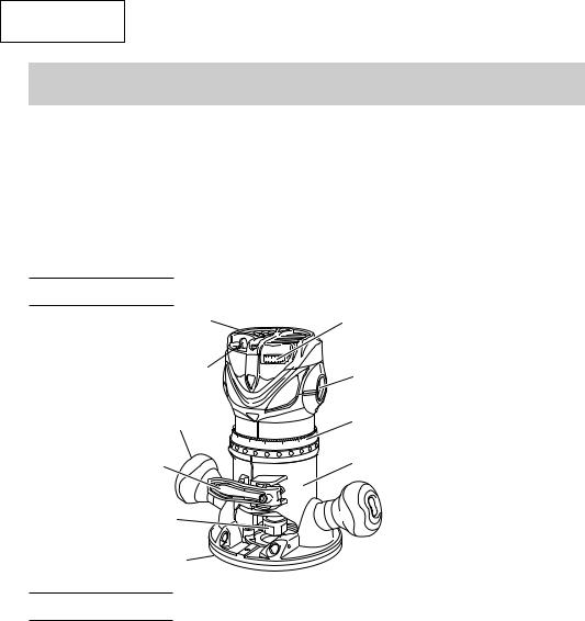
NAME OF PARTS
Motor Housing
Switch 
Handle
7/8 |
3/4 |
5/8 |
|
||
|
|
Lever
Collet Chuck
Sub Base
SPECIFICATIONS
1/2
Dial
Brush Cap
Scale Ring
3/8 |
1/4 |
|
Base
Fig. 1
Model |
M12VC |
|
M12SC |
Motor |
Single Phase, Series Commutator Motor |
||
Power source |
Single Phase 120V AC 60 Hz |
||
Collet chuck capacity |
1/2” (12.7 mm), 1/4” (6.35 mm) |
||
Current |
11 A |
|
|
No-load speed |
8000/min – 24000/min |
|
24000/min |
Weight (with cord) |
7.3 lbs (3.3 kg) |
|
|
|
|
|
|
8
English
ASSEMBLY AND OPERATION
APPLICATIONS
Woodworking jobs centered on grooving and beveling.
For example, grooving beveling, cutting, copying, engraving, shape cutting, combinations and others.
PRIOR TO OPERATION
1.Power source
Ensure that the power source to be utilized conforms to the power source requirements specified on the product nameplate.
2.Power switch
Ensure that the switch is in the OFF position. If the plug is connected to a receptacle while the switch is in the ON position, the power tool will start operating immediately and can cause serious injury.
3.Extension cord
When the work area is far away from the power source, use an extension cord of sufficient thickness and rated capacity. The extension cord should be kept as short as practicable.
 WARNING:
Damaged cord must be replaced or repaired.
4.Check the receptacle
If the receptacle only loosely accepts the plug, the receptacle must be repaired. Contact a licensed electrician to make appropriate repairs.
If such a fautly receptacle is used, it may cause overheating, resulting in a serious hazard.
5.Confirming condition of the environment
Confirm that the work site is placed under appropriate conditions conforming to prescribed precautions.
9
English
INSTALLING AND REMOVING BITS
 WARNING: Be sure to switch power OFF and disconnect the plug from the receptacle to avoid serious trouble.
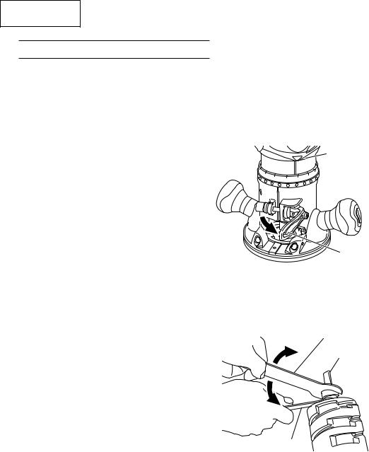
1. Installing bits
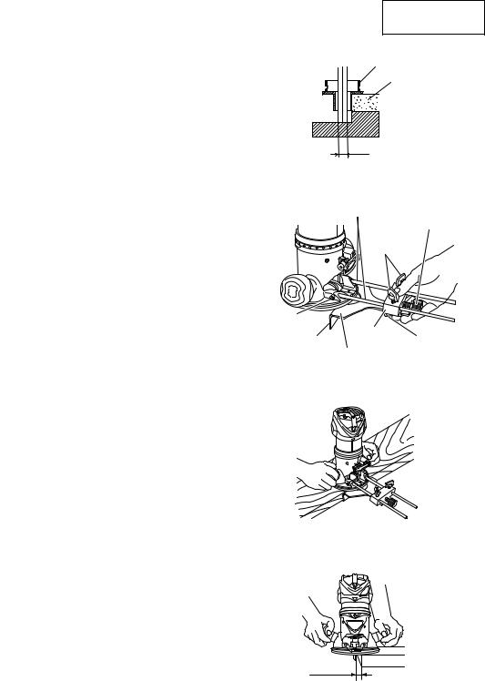
(1)Remove the motor housing from base as follows.
(a)Open the lever. (Fig. 2)
(b)While holding the base, turn the motor housing counterclockwise.
(c)Turn it until the pin in the base is disengaged from the groove in the motor housing. Lift the motor housing free from the base.
(2)Clean and insert shank of bit into the collet chunk until shank bottoms, then back it out approximately 1/16” (approx. 2 mm).
(3)With the bit inserted and 16 mm wrench holding the armature shaft, use the 23 mm wrench to firmly tighten the collet chuck in a clockwise direction (viewed from under the router). (Fig. 3)
(4)When using the 1/4” diameter shank bit, replace the equipped collet chuck with the one for 1/4” diameter shank bit which is provided as the standard accessory.
 CAUTION:
Ensure that the collet chuck is firmly tightened after inserting a bit. Failure to do so will result in damage to the collet chuck.
2.Removing bits
When removing the bits, do so by following the steps for installing bits in reverse order.
Motor
Housing
 Base
Base
Lever
Fig. 2
23mm Loosen Wrench
Bit
Collet
 Chuck
Chuck
Tighten
16mm Wrench
Fig. 3
10
English
INSTALLING THE MOTOR HOUSING
 WARNING: Be sure to switch power OFF and disconnect the plug from the
|
receptacle to avoid serious trouble. |
|
||
1. |
Installing the motor housing |
Motor |
|
|
Housing |
|
|||
(1) |
Open the lever. |
Pin |
Groove |
|
(2) |
While holding the base, insert the motor |
|||
|
||||
|
housing into the base aligning the pin with |
Knob Nut |
|
|
|
the groove in the base. |
|
|
|
(3) |
Confirm that the pin and the groove are |
|
|
|
|
aligning. Rotate the motor housing |
|
Lever |
|
|
clockwise into the base. |
Base |
|
|
(4) |
Close the lock lever. |
|
||
CAUTION: |
Fig. 4 |
|
You should be able to clamp the locking lever without excessive force. Excessive force may damage the base. You should not be able to move the motor in the base when the lever is clamped. To adjust the lever’s clamping force, open the locking lever and turn the knob nut in small increments. Turning the knob nut clockwise tightens the lever, while turning the knob nut counterclockwise loosens the lever.
HOW TO USE THE ROUTER
 WARNING: Be sure to switch power OFF and disconnect the plug from the receptacle to avoid serious trouble.
1. Adjusting depth of cut
(1)Place the tool on a flat wood surface.
(2)Open the lever and turn the motor housing until the bit just touches the flat surface. (Fig. 5)
(3)Clamp the lever down until the point where a click can be felt. (Fig. 6)
NOTE:
The motor housing can be temporarily secured by clamping the lever (the motor housing does not slide down by its own weight).
If the motor housing slides down, make adjustments by tightening the knob nut. Turning the knob nut clockwise tightens the lever, while turning the knob nut counterclockwise loosens the lever.
Index Line
Motor
Housing  Graduation
 Scale Ring
Base |
Lever |
|
|
|
Fig. 5 |
Knob Nut |
|
Lever
Fig. 6
11
English
(4)While holding up the base slightly, turn the motor housing clockwise until the index line on the motor housing reaches the desired depth indicated on the scale ring. (Fig. 5)
(5)Close the lever firmly.
2.Adjusting the rotation speed (Model M12VC only)
The M12VC have an electronic control system that allows stepless rpm changes. As shown in Fig. 7 dial position “1” is for minimum speed and position “6” for maximum speed.
3.Centering the template guide adapter
 WARNING: Be sure to switch power OFF and disconnect the
plug from the receptacle to avoid serious trouble.
(1)Loosen the 2 template guide adapter screws, so that the template guide adapter can be moved. (Fig. 8)
(2)Insert the centering gauge through the hole in the template guide adapter and into the collet chuck. (Fig. 9)
(3)Tighten the collet chuck by hand.
(4)Tighten the lever. (This aligns the center of the template guide adapter.)
(5)Tighten the template guide adapter screws, and pull out the centering gauge.
4. Guiding the router
(1)Template guide (M12VC, M12SC: Optional accessory)
Use the template guide when employing a template for producing a large quantitiy of identically shaped products. (Fig. 10)
As shown in Fig. 11, to install insert template guide in center hole in template guide adapter and secure in place with the lock nut.
A template is a profiling mold made of plywood or thin lumber. When making a template, pay particular attention to the matters cescribed blow and illustrated in Fig. 12.
Dial
6 5
Fig. 7
Screw
Template
Guide Adapter
Fig. 8
Template
Centering Guide Adapter
Gauge
Screw
Collet
Chuck
Lever
Fig. 9
Template
Fig. 10
Lock Nut
Template |
Template |
Guide |
Guide Adapter |
|
Fig. 11 |
12
English
When using the router along the interior plane of the template, the dimensions of the finished product will be less than the dimensions of the template by an amount equal to dimension “A”, the difference between the radius of the template guide and the radius of the bit. The reverse is frue when using the router along the exterior of the template.
Secure the template to the workpiece. Feed the router in the manner that the template guide moves along the template as shown in Fig. 12.
(2) Straight guide (optional accessory)
Use straight guide for chamfering and groove cutting along the materials side.
1 Insert the guide bar into the hole in the bar holder, then lightly tighten the 2 wing bolts
(A) on top of the bar holder.
2 Insert the guide bar into the hole in the base, then firmly tighten the 2 hex socket bolts (standard accessories).
3Make minute adjustments of the dimensions between the bit and the guide surface with the feed screw, then firmly tighten the 2 wing bolts (A) on top of the bar holder and the wing bolt (B) that secures the straight
guide. (Fig.13)
4As shown in Fig. 14, securely attach the bottom of the base to processed surface of the materials. Feed the router while keeping the guide plane on the surface of the
materials.
5. Cutting
Template Guide
Template
A
Fig. 12
Guide Bar
Feed Screw
Wing
Bolt (A)
Hex |
|
|
|
Socket |
Bar |
|
|
Bolt |
Wing |
||
Holder |
|||
Guide |
Bolt (B) |
||
Straight |
|||
Plane |
|||
|
|||
|
Guide |
|
|
|
Fig. 13 |
|
WARNING: |
Fig. 14 |
Wear eye protection when operating this tool.
Keep your hands, face and other body parts away from the bits and any other rotating
parts, while operating the tool.
(1) The bit must be kept clear of the materials
which are to be cut, when the power is being turned on. (Fig. 15)
(2) Then turn the tool on and wait until the bit
attains full speed.
Separate
Fig. 15
13

English
(3)The bit rotates clockwise (arrow direction indicated on the base). To obtain maximum conformance with the feed directions shown in Fig. 16.
NOTE:
Router feed Router feed
workpiece Rotation of bit
Fig. 16
Moving the tool forward fast may cause a poor quality of cut, or damage to the bit or motor. Moving the tool forward too slowly may burn and mar the cut.
The proper feed rate will depend on the bit size, the kind of workpiece and depth of cut. Before beginning the cut on the actual workpiece, it is advisable to make a sample cut on a piece of scrap lumber. This will show exactly how the cut will look as well as enable you to check dimensions.
Abnormalities and overloads will trigger the overload protector, and stop operation. Remove the load immediately, and turn the power off, then on. The rotation speed should return to normal.
Do not use a power generator as the power source. It may cause the rotation speed to fluctuate.
When using the straight guide, be sure to install it on the right side in the feed direction. This will help to keep it flush with the side of the workpiece.
14
English
MAINTENANCE AND INSPECTION
 WARNING: Be sure to switch power OFF and disconnect the plug from the receptacle during maintenance and inspection.
1.Inspecting the screws
Regularly inspect all screws and ensure that they are fully tightened. Should any of the screws be loosened, retighten them immediately.
 WARNING: Using this router with loosened screws is extremely dangerous.
2. Inspecting the carbon brushes (Fig. 17) |
|
|
The motor employs carbon brushes which |
|
|
are consumable parts. Replace the carbon |
43 |
|
brush with a new one when it becomes worn |
||
|
||
to its wear limit. Always keep carbon |
No. of carbon |
|
brushes clean and ensure that they slide |
|
|
freely within the brush holders. |
|
|
|
Fig. 17 |
 CAUTION: Using this router with a carbon brush which is worn in excess of the wear limit will damage the motor.
NOTE: Use HITACHI carbon brush No. 43 indicated in Fig. 17.
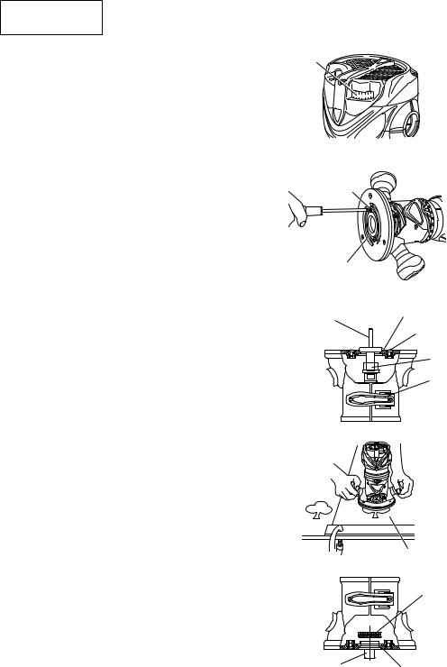
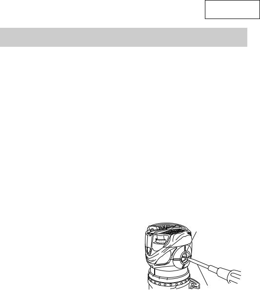
3. Replacing carbon brushes
Remove the brush caps with a slotted |
Brush Cap |
screwdriver. The carbon brushes can then |
|
be easily removed. (Fig. 18) |
|
4. Service and repairs
All quality power tools will eventually require servicing or replacement of parts because of wear from normal use. To assure that only authorized replacement parts will be used, all service and repairs must be performed by a HITACHI AUTHORIZED SERVICE CENTER, ONLY.
5. Service parts list
Slotted-head
Screwdriver
Fig. 18
 CAUTION: Repair, modification and inspection of Hitachi Power Tools must be carried out by a Hitachi Authorized Service Center.
This Parts List will be helpful if presented with the tool to the Hitachi Authorized Service Center when requesting repair or other maintenance. In the operation and maintenance of power tools, the safety regulations and standards prescribed in each country must be observed.
15

English
6.Service parts list
A:Item No.
B:Code No.
C:No. Used
D:Remarks
 CAUTION: Repair, modification and inspection of Hitachi Power Tools must be carried out by an Hitachi Authorized Service Center.
This Parts List will be helpful if presented with the tool to the Hitachi Authorized Service Center when requesting repair or other maintenance. In the operation and maintenance of power tools, the safety regulations and standards prescribed in each country must be observed.
MODIFICATIONS:
Hitachi Power Tools are constantly being improved and modified to incorporate the latest technological advancements.
Accordingly, some parts (i.e. code numbers and/or design) may be changed without prior notice.
16
English
ACCESSORIES
 WARNING: ALWAYS use Only authorized HITACHI replacement parts and accessories. NEVER use replacement parts or accessories which are not intended for use with this tool. Contact HITACHI if you are not sure whether it is safe to use a particular replacement part or accessory with your tool. The use of any other attachment or accessory can be dangerous and could cause injury or mechanical damage.
NOTE:
Accessories are subject to change without any obligation on the part of the HITACHI.
STANDARD ACCESSORIES
1. Model M12VC, M12SC
(1)1/4” Collet Chuck (Code No. 323-293)
(2)Template Guide Adapter (attaches to the router) (Code No. 323-272)
(3)Centering Gauge (Code No. 323-296)
(4)16 mm Wrench (Code No. 323-294)
(5)23 mm Wrench (Code No. 323-295)
2. Model KM12VC, KM12SC
(1)1/4” Collet Chuck (Code No. 323-293)
(2)Template Guide Adapter (attaches to the router) (Code No. 323-272)
(3)Centering Gauge (Code No. 323-296)
(4)16 mm Wrench (Code No. 323-294)
(5)23 mm Wrench (Code No. 323-295)
(6)Large Hole Sub Base (Code No. 323-297)
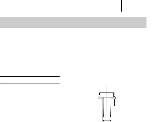
(7)Template Guide (Fig. 19)
(8)Lock Nut (Code No. 323-305)
(9)Chip Cover (Code No. 323-292) (10)Case (Code No. 323-358)
C
A
B
Code |
A |
B |
C |
|
No. |
||||
|
|
|
||
|
|
|
|
|
323-298 |
1/4” |
5/16” |
5/32” |
|
(6.5 mm) |
(8 mm) |
(4 mm) |
||
|
||||
|
|
|
|
|
323-299 |
9/32” |
3/8” |
5/16” |
|
(7 mm) |
(9.5 mm) |
(8 mm) |
||
|
||||
|
|
|
|
|
323-300 |
11/32” |
7/16” |
5/32” |
|
(8.7 mm) |
(11.1 mm) |
(4 mm) |
||
|
||||
|
|
|
|
|
323-301 |
13/32” |
1/2” |
5/16” |
|
(10.3 mm) |
(12.7 mm) |
(8 mm) |
||
|
|
|
|
|
323-302 |
17/32” |
5/8” |
9/16” |
|
(13.5 mm) |
(16 mm) |
(14.3 mm) |
||
|
|
|
|
|
323-303 |
21/32” |
3/4” |
9/16” |
|
(16.6 mm) |
(19.1 mm) |
(14.3 mm) |
||
|
|
|
|
|
323-304 |
5/8” |
51/64” |
9/16” |
|
(16 mm) |
(20.2 mm) |
(14.3 mm) |
||
|
||||
|
|
|
|
Fig. 19
17
English
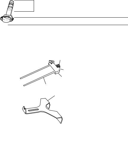
OPTIONAL ACCESSORIES …………… sold separately
(1)Straight Guide Set (Code No. 323-342) 1Bar Holder (Code No. 323-343) 2Feed Screw (Code No. 956-793) 3Wing Bolt (Code No. 301-806) 4Guide Bar (Code No. 323-345) 5Straight Guide (Code No. 323-344)
2

 3
3
1
4
5
(2) Dust Collector Set (Code No. 323-346)
NOTE:
Specifications are subject to change without any obligation on the part of the HITACHI.
18

Français
INFORMATIONS IMPORTANTES DE SÉCURITÉ
Lire et comprendre toutes les précautions de sécurité, les avertissements et les instructions de fonctionnement dans ce mode d’emploi avant d’utiliser ou d’entretenir cet outil motorisé.
La plupart des accidents causés lors de l’utilisation ou de l’entretien de l’outil motorisé proviennent d’un non respect des règles ou précautions de base de sécurité. Un accident peut la plupart du temps être évité si l’on reconnaît une situation de danger potentiel avant qu’elle ne se produise, et en observant les procédures de sécurité appropriées.
Les précautions de base de sécurité sont mises en évidence dans la section “SECURITE” de ce mode d’emploi et dans les sections qui contiennent les instructions de fonctionnement et d’entretien.
Les dangers qui doivent être évités pour prévenir des blessures corporelles ou un endommagement de la machine sont identifiés par AVERTISSEMENTS sur l’outil motorisé et dans ce mode d’emploi.
NE JAMAIS utiliser cet outil motorisé d’une manière qui n’est pas spécifiquement recommandée par HITACHI.
SIGNIFICATION DES MOTS D’AVERTISSEMENT
AVERTISSEMENT indique des situations potentiellement dangereuses qui, si elles sont ignorées, pourraient entraîner la mort ou de sérieuses blessures.
PRECAUTION indique des situations dangereuses potentilles qui, si elles ne sont pas évitées, peuvent entraîner de mineures et légères blessures ou endommager la machine.
REMARQUE met en relief des informations essentielles.
19

Français
SECURITE
REGLES GENERALE DE SECURITE
 AVERTISSEMENT: Lire et coxmprendre toutes les instructions.
Un non respect de toutes les instructions ci-dessous peut entraîner une électrocution, un incendie et/ou de sérieuses blessures personnelles.
CONSERVER CES INSTRUCTIONS
1.Zone de travail
(1)Garder la zone de travail propre et bien éclairée. Les établis mal rangés et les zones sombres invitent aux accidents.
(2)Ne pas utiliser les outils motorisés dans une atmosphère explosive, telle qu’en présence de liquides inflammables, de gaz ou de poussières. Les outils motorisés créent des étincelles qui risquent d’enflammer la poussière ou les vapeurs.
(3)Tenir les spectateurs, les enfants et les visiteurs éloignés, lors de l’utilisation de l’outil motorisé. Une distraction peut faire perdre le contrôle de la machine.
2.Sécurité électrique
(1)Brancher les outils mis à la terre dans une prise correctement installée et mise à la terre conformément aux codes et ordonnances. Ne jamais retirer la lame de terre ni modifier la fiche de quelque façon que ce soit. Ne pas utiliser d’adaptateurs de fiche. Si l’on n’est pas sûr que la prise soit correctement mise à la terre, consulter un électricien qualifié. Si les outils présentent un mauvais fonctionnement électrique ou tombent en panne, la mise à la terre offre un chemin de faible résistance qui permet d’éloigner l’électricité de l’utilisateur.
(2)Eviter tout contact corporel avec les surfaces mises à la terre telles que les canalisations, les radiateurs, les réchauds et les réfrigérateurs. Il y a un risque accru d’électrocution si son corps est mis à la terre.
(3)Ne pas exposer les outils motorisés à la pluie ou à l’humidité. De l’eau pénétrant à l’intérieur de l’outil motorisé augmente le risque d’électrocution.
(4)Ne pas maltraiter le cordon d’alimentation. Ne jamais utiliser le cordon pour porter les outils ou tirer sur la fiche du réceptacle. Garder le cordon à l’écart de la chaleur, de l’huile, des arêtes coupantes ou des pièces en mouvement. Remplacer les cordons endommagés immédiatement. Des cordons endommagés augmentent le risque d’électrocution.
(5)Lors de l’utilisation d’un outil motorisé, utiliser un cordon de rallonge extérieur marqué “W-A” ou “W”. Ces cordons sont prévus pour une utilisation extérieure et réduisent les risques d’électrocution.
3.Sécurité personnelle
(1)Rester sur ses gardes, regarder ce que l’on fait et utiliser son sens commun lors de l’utilisation d’un outil motorisé. Ne pas utiliser un outil en état de fatigue ou sous l’influence de drogues, d’alcool ou de médicaments. Un moment d’inattention lors de l’utilisation de l’outil motorisé peut entraîner de sérieuses blessures personnelles.
20
Français
(2)S’habiller correctement. Ne pas porter des vêtements larges ou des bijoux. Attacher les cheveux longs. Tenir ses cheveux, vêtements et ses gants éloignés des parties mobiles. Les vêtements larges, les bijoux et les cheveux longs peuvent se prendre dans les parties mobiles.
(3)Eviter tout démarrage accidentel. S’assurer que le l’interrupteur d’alimentation est sur la position d’arrêt avant de brancher la machine. Transporter l’appareil avec les doigts sur l’interrupteur d’alimentation ou brancher un outil avec l’interrupteur sur la position marche invite aux accidents.
(4)Retirer les clefs d’ajustement ou les commutateurs avant de mettre l’outil sous tension. Une clef qui est laissée attachée à une partie tournante de l’outil peut provoquer une blessure personnelle.
(5)Ne pas trop présumer de ses forces. Garder en permanence une position et un
équilibre correct. Une position et un équilibre correct permettent un meilleur contrôle de l’outil dans des situations inattendues.
(6)Utiliser un équipement de sécurité. Toujours porter une protection pour les yeux.
Utiliser un masque à poussière, des chaussures de sécurité antidérapantes, un casque dur et une protection pour les oreilles dans les conditions appropriées.
4.Utilisation de l’outil et entretien
(1)Utiliser un étau ou toutes autres façons de fixer et maintenir la pièce à usiner sur une plate-forme stable. Tenir la pièce avec la main ou contre son corps est instable et peut conduire à une perte de contrôle de l’outil.
(2)Ne pas forcer sur l’outil. Utiliser l’outil correct pour l’application souhaitée. L’outil correct réalisera un meilleur et plus sûr travail dans le domaine pour lequel il a été conçu.
(3)Ne pas utiliser un outil s’il ne se met pas sous ou hors tension avec un interrupteur.
Un outil qui ne peut pas être commandé avec un interrupteur est dangereux et doit être réparé.
(4)Déconnecter la fiche de la source d’alimentation avant de réaliser tout ajustement, changement d’accessoires ou pour ranger l’outil. De telles mesures de sécurité réduisent le risque que l’outil ne démarre accidentellement.
(5)Ranger les outils inutilisés hors de la portée des enfants et des autres personnes inexpérimentées. Les outils sont dangereux dans les mains de personnes inexpérimentées.
(6)Entretenir les outils avec soin. Maintenir les outils de coupe affûtés et propres.
Des outils correctement entretenus, avec des tranchants bien affûtés, sont moins susceptibles de se coincer et sont plus faciles à contrôler.
(7)Vérifier les défauts d’alignement ou grippage des parties mobiles, les ruptures des pièces et toutes les autres conditions qui peuvent affecter le fonctionnement des outils. En cas de dommage, faire réparer l’outil avant de l’utiliser. Beaucoup d’accidents sont causés par des outils mal entretenus.
(8)Utiliser uniquement les accessoires recommandés par le fabricant pur le modèle utilisé. Des accessoires qui peuvent convenir à un outil, peuvent devenir dangereux lorsqu’ils sont utilisés avec un autre outil.
5.Réparation
(1)La réparation de l’outil ne doit être réalisée uniquement par un réparateur qualifié.
Une réparation ou un entretien réalisé par un personnel non qualifié peut entraîner des risques de blessures.
21
 Loading...