


HITACHI INVERTER
J300 SERIES
INSTRUCTION MANUAL
Three phase input 200/400V class
J300 U : USA version
After reading this manual, keep it at hand for future reference.
NB506XC
Hitachi, Ltd.
Tokyo Japan
Phone: 800.894.0412 - Fax: 888.723.4773 - Web: www.clrwtr.com - Email: info@clrwtr.com
SAFETY
For the Best Results with J300 Series inverter, read this manual and all of the warning sign attached to the inverter carefully before installing and operating it, and follow the instructions exactly. Keep this manual handy for your quick reference.
Definitions and Symbols
A safety instruction (message) is given with a hazard alert symbol and a signal word;
WARNING or CAUTION. Each signal word has the following meaning throughout this manual.
|
This symbol means hazardous high voltage. It used to call your attention to |
||
|
items or operations that could be dangerous to your and other persons operat- |
||
|
ing this equipment. |
|
|
|
Read these message and follow these instructions carefully. |
||
|
This is the “Safety Alert Symbol.” This symbol is used to call your attention |
||
|
to items or operations that could be dangerous to your or other persons operat- |
||
|
ing this equipment. Read these messages and follow these instructions |
||
|
carefully. |
|
|
WARNING |
WARNING |
|
|
|
Indicates a potentially hazardous situation which, if not avoided, can result in |
||
|
serious injury or death. |
|
|
CAUTION |
CAUTION |
|
|
|
Indicates a potentially hazardous situation which, if not avoided, can result in |
||
|
minor to moderate injury, or serious damage of product. |
||
|
The matters described under |
|
may, if not avoided, lead to |
|
CAUTION |
||
|
serious results depending on the situation. |
Important matters are described in |
|
|
CAUTION (as well as WARNING), so be sure to observe them. |
||
NOTE |
NOTE: Notes indicate an area or subject of special merit, emphasizing either |
||
|
the product’s capabilities or common errors in operation or maintenance. |
||
HAZARDOUS HIGH VOLTAGE
Motor control equipment and electronic controllers are connected to hazardous line voltages. When servicing drives and electronic controllers, there might be exposed components with cases or protrusions at or above line potential. Extreme care should be taken to protect against shock.
Stand on an insulating pad and make it a habit to use only one hand when checking components. Always work with another person in case an emergency occurs. Disconnect power before checking controllers or performing maintenance. Be sure equipment is properly grounded. Wear safety glasses whenever working on an electronic controllers or rotating electrical equipment.
- i -
Phone: 800.894.0412 - Fax: 888.723.4773 - Web: www.clrwtr.com - Email: info@clrwtr.com
PRECAUTIONS
 WARNING: This equipment should be installed, adjusted and serviced by qualified electrical maintenance personal familiar with the construction and operation of the equipment
and the hazards involved. Failure to observe this precaution could result in bodily injury.
WARNING : The user is responsible for ensuring that all driven machinery, drive train mechanism not supplied by Hitachi, Ltd., and process line material are capable of safe operation at an applied frequency of 150% of the maximum selected frequency range to the AC motor. Failure to do so can result in destruction of equipment and injury to personnel should a single point failure occur.
WARNING : For protection, install a leak breaker type with a high frequency circuit capable of large currents to avoid an unnecessary operation. The ground fault protection circuit is not designed to protect personal injury.
WARNING : HAZARD OF ELECTRICAL SHOCK. DISCONNECT INCOMING POWER BEFORE WORKING ON THIS CONTROL.
AVERTISSEMENT : RISQUE DE CHOC ELECTRIQUE COUPER L'ALIMENTATION AVANT LE DEPANNAGE DE CETTE COMMANDE.
WARNING : SEPARATE MOTOR OVERCURRENT, OVERLOAD AND OVERHEATING PROTECTION IS REQUIRED TO BE PROVIDED IN ACCORDANCE WITH THE SAFETY CODES REQUIRED BY JURISDICTIONAL AUTHORITIES.
AVERTISSEMENT : LE MOTEUR DOIT ETRE MUNI D'UNE PROTECTION DISTINCTE CONTRE LES SURINTENSITES, LA SURCHARGE ET LA SURCHAUFFE,CONFORMEMENT AU CODE CANADIEN DE L'ELECTRICITE< PREMIERE PARTIE.
 CAUTION: These instructions should be read and clearly understood before working on J300 series equipment.
 CAUTION: Proper grounds, disconnecting devices and other safety devices and their location are the responsibility of the user and are not provided by Hitachi, Ltd.
CAUTION: Be sure to connect a motor thermal switch or overload device to the J300 series controller to assure that the inverter will shut down in the event of an overload or an overheated motor.
CAUTION: DANGEROUS VOLTAGE EXISTS UNTIL CHARGE LIGHT IS OFF.
 ATTENTION: PRESENCE DE TENSIONS DANGEREUSES TANT QUE LE VOYANT N'EST PAS ETEINT.
 CAUTION: Rotating shafts and above ground electrical potentials can be hazardous. Therefore, it is strongly recommended that all electrical work conform to the National Electrical Codes and local regulations. Installation, alignment and maintenance should be performed only by qualified personnel. Factory recommended test procedures, included in the instruction manual, should be followed. Always disconnect electrical power before working on the unit.
- ii -
Phone: 800.894.0412 - Fax: 888.723.4773 - Web: www.clrwtr.com - Email: info@clrwtr.com

NOTE : POLLUTION DEGREE 2
The inverter must be used in environment of the degree 2.
Typical constructions that reduce the possibility of conductive pollution are;
1)The use of an un-ventilated enclosure
2)The use of a filtered ventilated enclosure when the ventilation is fan forced that is, ventilation is accomplished by one or more blowers within the enclosure that provide a positive intake and exhaust.
NOTE : ENCLOSURE SIZE FOR 75 kW TO 110 kW
The inverter, 75kW to 110kW must be installed into an enclosure with dimmensions no less than 183cm (72 in) by 183cm (72 in) by 60cm (24 in).
NOTE : ENCLOSURE SIZE FOR 132 kW AND BIGGER
The inverters, 132kW and bigger, are complied as recognizedcomponents.
Therse devices are intended for use in an overall ecclosure with an internal ambient of
40 degree C for variable torque rating or 50 degree C for constant torque rating maximum. End product temperature testing should be conducted to verify sufficient forced air ventilation is provided to maintain this ambient in room ambient of 10-40 degree C.
Based upon component level testing , end product temperature testing may be conducted at any convenient room ambient in the rangeof 20-40 dwgree C, unless the room ambient in the intended application exceeds 40degree C, in which case testing should be conducted at the elevated ambient.
Enclosure internal ambient temperature should be measured above the drive on to the upper left or right side. Temperature measurments on the drive itself should not be necessary.
NOTE : SET OF MOTOR CAPACITY AND POLES (A1, A2)
When data does not match a capacity of connected motor , it may cause unstaible motor operation. Set proper motor capacity (kW) and motor poles even under V/F control mode.
- iii -
Phone: 800.894.0412 - Fax: 888.723.4773 - Web: www.clrwtr.com - Email: info@clrwtr.com
Revision History Table
No. |
Revision Contents |
The Date |
Operation |
|
of Issue |
Manual No. |
|||
|
|
|||
|
|
|
|
|
1 |
Page iii : Pollution degree |
Aug. 1997 |
NB506XA |
|
|
Page 2-1 : Description of inverter model |
|
|
|
|
Page4-2 : Change of note |
|
|
|
|
Page 5-8, 5-9 : Addition of 750 to 1100H |
|
|
|
|
Page 5-10 : Terminal description |
|
|
|
|
Page 11-1,11-2,11-3 : addition of 750 to 1100H |
|
|
|
2 |
Page iii : Enclosure size |
Feb. 1998 |
NB506XB |
|
|
Page 4-1 : Enclosure size, page 7-5; note 3, |
|
|
|
|
Page 7-11: F8 boost value in VP1 to 3 |
|
|
|
|
Page 7-15: A0 note for boost value |
|
|
|
|
Page 12-13: additio of note 1 |
|
|
|
|
Page A25-A31: addition of line for set value |
|
|
|
|
Page A-33: deletion of A-93 on clause |
|
|
|
3 |
Page iii: note for 132 kW to 220 kW is added |
Feb. 1999 |
NB506XC |
|
|
Page 2-1: added 132 to 220kW |
|
|
|
|
Page 4-1; note for 132 kW to 220 kW is added |
|
|
|
|
page 4-2: note,note1 corrected 110kW->260kW |
|
|
|
|
page 5-8: added 1320 to 2200H in table |
|
|
|
|
Page 5-10: terminal layout corrected |
|
|
|
|
Page7-5: corrected monitor d3 39 to 99 |
|
|
|
|
Page7-18: A10, addition of 1320 to 2200H |
|
|
|
|
Page 11-1,2,3: added 1320 to 2200H |
|
|
|
|
|
|
|
- iv -
Phone: 800.894.0412 - Fax: 888.723.4773 - Web: www.clrwtr.com - Email: info@clrwtr.com
TABLE OF CONTENTS
|
|
Page |
1. |
SAFETY PRECAUTIONS .......................................................................................... |
1-1 |
2. |
INSPECTION UPON UNPACKING ........................................................................ |
2-1 |
3. |
APPEARANCE AND NAMES OF PARTS ............................................................. |
3-1 |
4. |
INSTALLATION .......................................................................................................... |
4-1 |
5. |
WIRING ......................................................................................................................... |
5-1 |
6. |
OPERATION ................................................................................................................. |
6-1 |
7. |
OPERATION OF THE DIGITAL OPERATOR ...................................................... |
7-1 |
8. |
PROTECTION FUNCTIONS ..................................................................................... |
8-1 |
9. |
TROUBLESHOOTING ............................................................................................... |
9-1 |
10. |
MAINTENANCE AND INSPECTION ..................................................................... |
10-1 |
11. |
STANDARD SPECIFICATIONS .............................................................................. |
11-1 |
12. |
FUNCTIONS WHEN USING THE OPTIONAL REMOTE OPERATOR .......... |
12-1 |
13. |
SERVICE ....................................................................................................................... |
13-1 |
APPENDIX 1 ....................................................................................................................... |
A-1 |
|
APPENDIX 2 ....................................................................................................................... |
A-15 |
|
APPENDIX 3 ....................................................................................................................... |
A-19 |
|
APPENDIX 4 ....................................................................................................................... |
A-20 |
|
APPENDIX 5 ....................................................................................................................... |
A-21 |
|
APPENDIX 6 ....................................................................................................................... |
A-24 |
|
APPENDIX 7 ....................................................................................................................... |
A-25 |
|
APPENDIX 8 ....................................................................................................................... |
A-32 |
|
- v -
Phone: 800.894.0412 - Fax: 888.723.4773 - Web: www.clrwtr.com - Email: info@clrwtr.com

1. SAFETY PRECAUTIONS
1.Installation
 CAUTION
* |
Be sure to install the unit on flame resistant material such as metal. ............ |
p. 4-1 |
|
Otherwise, there is a danger of fire. |
|
* |
Be sure not to place anything inflammable in the vicinity. ........... |
p. 4-1 |
|
Otherwise, there is a danger of fire. |
|
*Be sure not to let the foreign matter enter such as cut wire refuse, spatter ........... p. 4-1 from welding, iron refuse, wire, dust, etc.
Otherwise, there is a danger of fire.
* Be sure to install it in a place which can bear the weight according to ........... |
p. 4-1 |
the specifications in the text (4. Installation). |
|
Otherwise, it may fall and there is a danger of injury. |
|
* Be sure to install the unit on a perpendicular wall which is not subject ........... |
p. 4-1 |
to vibration. |
|
Otherwise, it may fall and there is a danger of injury. |
|
* Be sure not to install and operate an inverter which is damaged or parts ........... |
p. 4-1 |
of which are missing. |
|
Otherwise, there is a danger of injury. |
|
* Be sure to install it in a room which is not exposed to direct sunlight ........... |
p. 4-1 |
and is well ventilated. Avoid environments which tend to be high in |
|
temperature, high in humidity or to have dew condensation, as well as |
|
places with dust, corrosive gas, explosive gas, inflammable gas, |
|
grinding-fluid mist, salt damage, etc. |
|
Otherwise, there is a danger of fire. |
|
* Be sure that the wall surface is a nonflammable material, such as steel ........... |
p. 4-2 |
plate. |
|
2. |
Wiring |
|
|
|
|
|
|
|
WARNING |
|
|
|
|
|
|
|
* Be sure to ground the unit. |
............ |
p. 5-1 |
|
Otherwise, there is a danger of electric shock and/or fire. |
|
|
|
* Wiring work shall be carried out by electrical experts. |
............ |
p. 5-1 |
|
Otherwise, there is a danger of electric shock and/or fire. |
|
|
|
* Implement wiring after checking that the power supply is off. |
............ |
p. 5-1 |
|
It might incur electric shock and/or fire. |
|
|
|
* After installing the main body, carry out wiring. |
............ |
p. 5-1 |
|
Otherwise, there is a danger of electric shock and/or injury. |
|
|
|
* Wait until DC bus voltage is discharged after power supply is turned |
............ p. 5-10 |
|
|
off. |
|
|
|
Otherwise, there is a danger of electric shock. |
|
|
|
|
|
|
|
1-1 |
|
|
Phone: 800.894.0412 - Fax: 888.723.4773 - Web: www.clrwtr.com - Email: info@clrwtr.com

 CAUTION
*Make sure that the input voltage is:
Three phase 200 to 220 V/50 Hz, 200 to 230 V/60 Hz Three phase 380 to 415 V/50 Hz, 400 to 460 V/60 Hz
*Be sure not to input a single phase to a 3 phase type. Otherwise, there is a danger of fire.
*Be sure not to connect AC power supply to the output terminals [U (T1), V (T2), W (T3)].
Otherwise, there is a danger of injury and/or fire.
|
|
INPUT |
OUTPUT |
||||
Note) |
|
|
|
|
|
|
|
(L1) |
(L2) |
(L3) |
(T1) |
(T2) (T3) |
|||
R |
S |
T |
U |
V W |
|||
|
|
|
|
|
|
|
|
Power supply
............ p. 5-2
............ p. 5-2
............ p. 5-2
* Fasten the screws with the specified fastening torque. Check so that ............ |
p. 5-2 |
there is no loosening of screws. Otherwise, there is a danger of fire.
* Be sure to install an earth leakage breaker.
The ground fault protection is designed to detect current flowing to the ground upon power on. This function is to protect the inverter, not people. Install the earth leakage breaker to protect against the ground fault on wires between the inverter and the motor. (Use a breaker that is very sensitive to high frequency current so as not to cause malfunction.)
*Be sure to set the fuse(s) (the same phase as the main power supply) in the operation circuit.
Otherwise, there is a danger of fire.
*As for motor leads, earth leakage breakers and electromagnetic contactors, be sure to use the equivalent ones with the specified capacity (rated).
Otherwise, there is a danger of fire.
*Connection to wiring terminal must be reliabily fixed with two means of support.
............ p. 5-2
............ p. 5-2
............ p. 5-2
............ p. 5-2
1-2
Phone: 800.894.0412 - Fax: 888.723.4773 - Web: www.clrwtr.com - Email: info@clrwtr.com
 CAUTION
External or remote over load protection required, if multiple motors to ............ |
p. 5-4 |
be connected. |
|
For models J300-450LFU and -550LFU only , connect to branch circuit protected at maximum 300% of output current rating.
Suitable for use on a circuit capable of delivering not more than 10,000 rms symmetrical amperes,*** volts maximum,
(where *** = input voltage)
Alarm connection may contain harzordous live voltage even when |
............ p. 5-11 |
inverter is disconnected. In case of removing front cover for maintenance or inspection, confirm that incoming power for alarm connection is surely disconnected.
 CAUTION
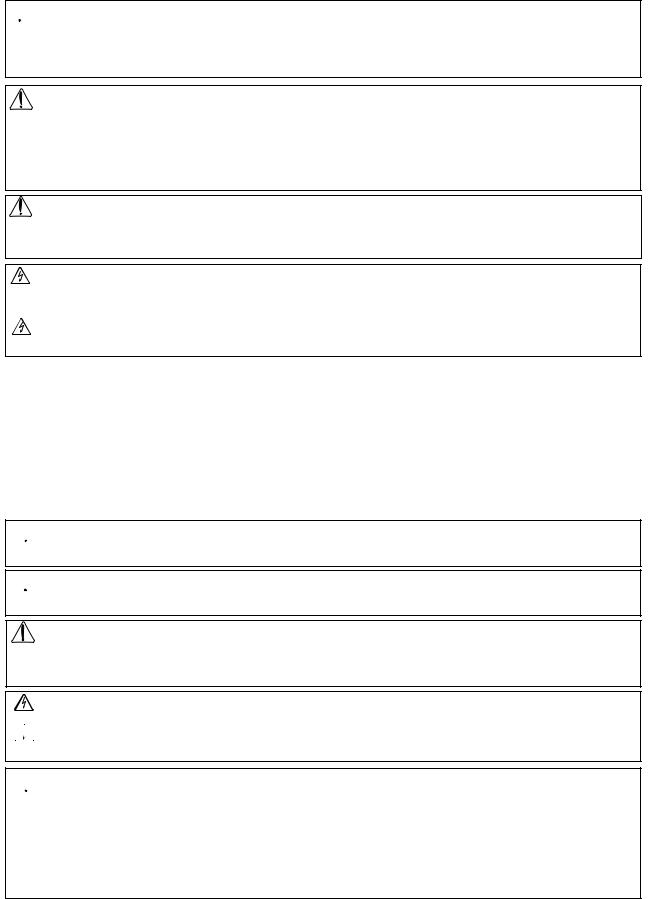
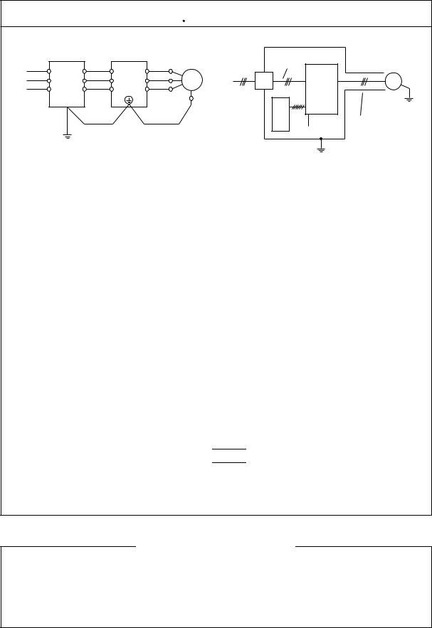
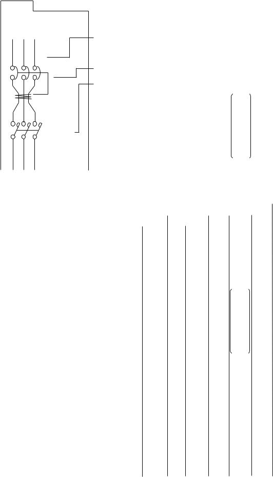
Input phase failure protection
(1)J300-U version inverter are provided with the phase failure protection on the power supply.
(2)When a buzzer, lamp, noise filter or transformer is connected between the input power terminals (L1, L2, L3) and input power fuses, input phase failure cannot be protected.
(L1) |
(L2) |
(L3) |
R |
S |
T |
|
L |
(Bad example) |
|
|
Noise filter
Fuse 

L |
(Good example) |
|
|
Power supply |
|
1-3
Phone: 800.894.0412 - Fax: 888.723.4773 - Web: www.clrwtr.com - Email: info@clrwtr.com

3.Control and operation
 WARNING
*Be sure to turn on the input power supply after mounting the surface cover. While being energized, be sure not to remove the cover. Otherwise, there is a danger of electric shock.
*Be sure not to operate the switches with wet hands. Otherwise, there is a danger of electric shock.
*While the inverter is energized, be sure not to touch the inverter terminals even during stoppage.
Otherwise, there is a danger of electric shock.
*If the re-try mode is selected, it may suddenly restart during the trip stop. Be sure not to approach the machine. (Be sure to design the machine so that personnel safety will be secured even if it restarts.) Otherwise, there is a danger of injury.
............ p. 6-1
............ p. 6-1
............ p. 6-1
............ p. 6-1
*Even if the power supply is cut for a short period of time, it may restart operation after the power supply is recovered if the operation command is given. If it may incur danger to personnel, be sure to make a circuit so that it will not restart after power recovery.
Otherwise, there is a danger of injury.
*The Stop Key is effective only when the function is set. Be sure to prepare the Key separately from the emergency stop.
Otherwise, there is a danger of injury.
............ p. 6-1
............ p. 6-1
*After the operation command is given, if the alarm reset is conducted, it ............ p. 6-1 will restart suddenly. Be sure to set the alarm reset after checking the
operation command is off. Otherwise, there is a danger of injury.
* Be sure not to touch the inside of the energized inverter or to put a bar ............ |
p. 6-1 |
into it. |
|
Otherwise, there is a danger of electric shock and/or fire. |
|
* The STOP/RESET key works only when a function is set. Prepare an ............ |
p. 7-1 |
emergency switch separately. The use of the STOP/RESET key as an |
|
emergency switch may cause an injury. |
|
1-4
Phone: 800.894.0412 - Fax: 888.723.4773 - Web: www.clrwtr.com - Email: info@clrwtr.com
 CAUTION
*Radiating fin and discharging resistor will have high temperature. Be sure not to touch them.
Otherwise, there is a danger of getting burned.
*Low to high speed operation of the inverter can be easily set. Be sure to operate it after checking the tolerance of the motor and machine. Otherwise, there is a danger of injury.
............ p. 6-2
............ p. 6-2
*If a motor is operated at a frequency higher than 60Hz, be sure to check ............ p. 6-2 the speeds of the motor and the machine with each manufacturer, and
after getting their consent, operate them. Otherwise, there is a danger of machine breakage.
* Check the following before and during the test run. |
............ p. 6-3 |
Otherwise, there is a danger of machine breakage. |
|
•Was the short-cut bar between +1 and + connected?
•Was the direction of the motor correct?
•Was the inverter tripped during acceleration or deceleration?
•Were the rpm and frequency meter correct?
•Were there any abnormal motor vibrations or noise?
•When overcurrent tripping or overvoltage tripping occurs during the test run, increase the acceleration time or deceleration time.
4.Maintenance, inspection and part replacement
 WARNING
*Be sure to turn off the power supply during maintenance and inspection.
*After the power supply has been turned off, you must always wait 10 minutes so that DC bus capacitors can discharge then start maintenance and inspection after the CHARGE lamp on the printed-circuit board has gone out. (Immediately after the lamp has gone out, there will be a residual voltage of about 50 V DC in the DC bus intermediate circuit.) Perform the work after the CHARGE lamp has stopped flickering.
*Make sure that only qualified persons will perform maintenance, inspection and part replacement. (Before starting the work, remove metallic objects from your person (wristwatch, bracelet, etc.)
(Be sure to use tools protected with insulation.)
Otherwise, there is a danger of electric shock and/or injury.
........... p. 10-1
........... p. 10-1
........... p. 10-1
1-5
Phone: 800.894.0412 - Fax: 888.723.4773 - Web: www.clrwtr.com - Email: info@clrwtr.com

 CAUTION
* When removing connectors, never pull the wires. (Wires for cooling |
........... p. 10-1 |
fan and thermal relay)
Otherwise, there is a danger of fire due to wire breakage and/or injury.
5. Appendix
 WARNING
* When the inverter stops due to a trip with retry mode selected, the |
........... p. A-15 |
|
|
motor restarts suddenly. Stand clear of the machine. Otherwise, you |
|
may be injured. (Design the machine in such a way that persons are |
|
protected against a restart of the machine.) |
|
*If the retry mode is selected, do not approach the inverter unnecessarily. ........... p. A-16 It will be restarted suddenly after it trips/stops. (Design the inverter so
that the safety can be assured even in such a restart.) Otherwise, bodily injury will result.
1-6
Phone: 800.894.0412 - Fax: 888.723.4773 - Web: www.clrwtr.com - Email: info@clrwtr.com
6.Others
 WARNING
*Never modify the unit.
Otherwise, there is a danger of electric shock and/or injury.
 CAUTION
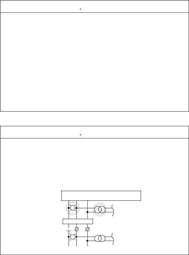
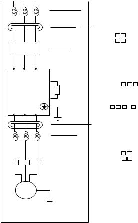
*Withstand voltage tests and insulation resistance tests (megger tests) are executed before the units are shipped, so that there is no need to conduct these tests before operation.
When conducting megger tests as a part of daily inspection, be sure that these tests are only executed between the main circuit and the ground. Do not execute megger tests on the control circuit.
(L1) |
(L2) |
(L3) (RB) |
(+) |
(–) |
(T1) |
(T2) |
(T3) |
R |
S |
T RB |
P |
N |
U |
V |
W |
FM P24 PLC FW • • •
Megohm-meter
Megohm-meter
*Do not attach or remove wiring or connectors (including Digital operator and Remote operator) when power is applied. Also, do not check signals during operation. Otherwise, a trip may occur or a failure may be caused. To stop the operation, be sure to use an operation instruction (FW,REV.) Do not turn power off within three minutes after it is turned on, or vice versa.
*Do not stop operation by switching off the electromagnetic(Mgo) contactors on the primary or secondary sides of the inverter.To stop the operation, be sure to use an operation instruction (FW,REV.) Do not turn power off within three
minutes after it is turned on, or vice versa.
|
Earth |
|
|
|
|
leakage |
|
|
|
|
breaker |
|
|
|
|
|
|
|
|
Power |
|
Mgo (L1) (L2) |
(L3) |
|
|
|
R , S , |
T |
supply
INV
ON,OFF
(Bad example)
|
ON,OFF |
|
|
|
|
(T1) (T2) (T3) |
|
U , V , W |
Motor |
|
|
FW |
|
|
|
PV24
Turn ON and OFF (Good example)
When there has been an instantaneous power failure, and if an operation instruction has been given, then the unit may restart operation after the power failure has ended. If there is a possibility that such an occurrence may harm humans, then install an electromagnetic contactor (Mgo) on the power supply side, so that the circuit does not allow automatic restarting after the power supply recovers. If the optional remote operator is used and the retry function has been selected, this will also cause automatic restarting when an operation instruction has been input, so please be careful.
1-7
Phone: 800.894.0412 - Fax: 888.723.4773 - Web: www.clrwtr.com - Email: info@clrwtr.com

 CAUTION
*Do not insert leading power factor capacitors or surge absorbers between the output terminals of the inverter and the motor.
Earth
leakage Surge absorber breaker
Power |
(L1)(L2)(L3) |
|
(T1)(T2)(T3) |
R, S, T, |
INV |
U, V, W, |
|
supply |
|
|
|
|
|
|
Motor
Leading power factor capacitor
*Be sure to ground the grounding terminal,  .
.
*When inspecting the unit, after turning the power supply off be sure to wait unitl the CHARGE lamp beside the control terminal is off before opening the cover.
(If the lamp is lit or still flickering, then the internal capacitor’s residual voltage is still dangerous.)
*MOTOR TERMINAL SURGE VOLTAGE SUPPRESSION FILTER (FOR THE 400 V CLASS)
In a system using an inverter of the voltage control PWM system, a surge voltage caused by the cable constants such as the cable length (especially when the distance between the motor and inverter is 10 m or more) and cabling method may occur at the motor terminal.
A dedicated filter of the 400 V class for suppressing this surge voltage is available, Please order one.
*PROTECTION AGAINST NOISE INTERFERENCE FROM INVERTER
The inverter uses many semiconductor switching elements such as transistors and IGBTs. Thus, a radio set or measuring instrument located near the inverter is susceptible to noise interference.
To protect the instruments from erroneous operation due to noise interference, they should be installed well apart from the inverter. It is also effective to shield the whole inverter structure.
Addition of an EMI filter on the input side of the inverter also reduces the effect of noise from commercial power line on external devices.
Note that external dispersion of noise from the power line can be minimized by connecting an EMI filter on the primary side of inverter.
1-8
Phone: 800.894.0412 - Fax: 888.723.4773 - Web: www.clrwtr.com - Email: info@clrwtr.com
 CAUTION
EMI filter
|
R1 |
R2 |
Power |
S1 |
S2 |
source |
T1 |
T2 |
Inverter |
|
Motor |
Power |
||
L1(L1) |
U |
(T1) U |
|||
source |
|||||
|
|||||
L2(L2) |
V |
(T2) V |
|
|
|
L3(L3) W |
(T3) W |
|
|
||
|
|
|
Terminal |
EMI |
|
|
|
|
for |
filter |
|
|
|
|
grounding |
|
|
Noise
Inverter
Remote operator |
|
|
Noise |
Motor
Ground the
frame.
Piping
(to be grounded) or shielded wire
Completely ground the shield made of metal screen, enclosed panel, etc. with as short a wire as possible.
*EFFECTS OF DISTRIBUTOR LINES ON INVERTERS
In the cases below involving a general-purpose inverter, a large peak current flows on the power supply side, sometimes destroying the converter module. Where such situations are foreseen, or the paired equipment must be highly reliable, install an AC reactor between the power supply and the inverter.
(A)The unbalance factor of the power supply is 3% or higher.
(B)The power supply capacity is at least 10 times greater than the inverter capacity (and the power supply capacity, 500 kVA or more).
(C)Abrupt power supply changes are expected. Examples:
(1)Several inverters are interconnected with a short bus.
(2)A thyristor converter and an inverter are interconnected with a short bus.
(3)An installed phase advance capacitor opens and closes.
In cases (A), (B) or (C), we recommend installing an AC reactor of 3% (in a voltage drop at rated current) with respect to the supply voltage on the power supply side.
*When occurring an EEPROM error ( 

 ), be sure to confirm the setting value again.
*When setting b contact to the reverse command ([REV] terminal), the inverter state automatically. Do not set to b contact.
GENERAL CAUTION
In all the illustrations in this manual, covers and safety devices are occasionally removed to describe the details. When the product is operated, make sure that the covers and safety devices are placed as they were specified originally and operate it according to the instruction manual.
1-9
Phone: 800.894.0412 - Fax: 888.723.4773 - Web: www.clrwtr.com - Email: info@clrwtr.com

2. INSPECTION UPON UNPACKING
Before installation and wiring, be sure to check the following:
•Make sure that there was no damage during transportation the unit.
•After unpacking the unit, make sure that the package contains one inverter and one operation manual
•Make sure that the product is the one you ordered by checking the specifications label on the front of the cover.
|
|
|
|
|
|
INVERTER |
|
|
|
|
|
|
||
|
HITACHI |
|
055HFU |
|||||||||||
|
J300 |
|
|
|||||||||||
|
|
|
|
INPUT |
|
|
|
|
|
OUTPUT |
|
|||
Input power supply, |
380-415V |
3 Ph |
50 Hz |
max:380-460V |
3 Ph |
|
||||||||
phase, and frequency |
400-460V |
3 Ph |
60 Hz |
Amps (CT) |
|
13 |
A/(VT) |
16 A |
||||||
Production year |
|
|
|
|
|
|
|
|
(CT) |
|
5.5kW(VT) |
7.5kW |
||
DATE |
|
|
|
|
|
|
|
|
|
|||||
1995 |
|
MFG. NO. |
J300U-055H251L |
|
|
|
||||||||
|
|
Hitachi, Ltd. Made in Japan |
|
|
NE15390 |
|||||||||
|
|
|
|
|
||||||||||
Model abbreviation
(The example is for the J300-055HFE2)
Output voltage Rated output current
Maximum applicable motor (4P kW) Production number
and factory control symbol
Contents of Specifications Label
If you discover any problems, contact your sales agent immediately.
Description of Inverter Model
J300 055 H F U
Series name
Version number
U : USA version
Structure type
F: with digital operator (Semi-closed, open type)
Input voltage
L : Three phase 200V class H : Three phase 400V class
Applicable motor capacity (4P.kW)
055: 5.5 kW |
550: |
55 kW |
075: 7.5 kW |
750: |
75 kW |
110: 11 kW |
900: |
90kW |
150: 15 kW |
1100: |
110 kW |
220: 22 kW |
1320: |
132 kW |
300: 30 kW |
1600: |
160kW |
370: 37 kW |
2200: |
220 kW |
450: 45 kW |
|
|
2-1
Phone: 800.894.0412 - Fax: 888.723.4773 - Web: www.clrwtr.com - Email: info@clrwtr.com

3. APPEARANCE AND NAMES OF PARTS
3.1Names of Parts
Blind cover
Front cover
A set screw
Charge lamp (LED)
Control circuit |
Digital |
Main circuit |
|
terminals |
operator |
||
terminals |
|||
|
|
Wiring holes
Cover
Case
3-1
Phone: 800.894.0412 - Fax: 888.723.4773 - Web: www.clrwtr.com - Email: info@clrwtr.com

4. INSTALLATION
 CAUTION
*Be sure to install the unit on flame resistant material such as metal. Otherwise, there is a danger of fire.
*Be sure not to place anything inflammable in the vicinity. Otherwise, there is a danger of fire.
*Be sure not to let the foreign matter enter such as cut wire refuse, spatter from welding, iron refuse, wire, dust, etc.
Otherwise, there is a danger of fire.
*Be sure to install it in a place which can bear the weight according to the specifications in the text (4. Installation).
Otherwise, it may fall and there is a danger of injury.
*Be sure to install the unit on a perpendicular wall which is not subject to vibration. Otherwise, it may fall and there is a danger of injury.
*Be sure not to install and operate an inverter which is damaged or parts of which are missing.
Otherwise, there is a danger of injury.
*Be sure to install it in a room which is not exposed to direct sunlight and is well ventilated. Avoid environments which tend to be high in temperature, high in humidity or to have dew condensation, as well as places with dust, corrosive gas, explosive gas, inflammable gas, grinding-fluid mist, salt damage, etc.
Otherwise, there is a danger of fire.
NOTE : ENCLOSURE SIZE FOR 75 kW to 110kW
The inverters, 75kW to 110kW must be installed into an enclosure with dimmensions no less than 183cm (72 in) by 183cm (72 in) by 60cm (24 in).
NOTE : ENCLOSURE SIZE FOR 132 kW AND BIGGER
The inverters, 132kW and bigger, are complied as recognizedcomponents.
Therse devices are intended for use in an overall ecclosure with an internal ambient of
40 degree C for variable torque rating or 50 degree C for constant torque rating maximum. End product temperature testing should be conducted to verify sufficient forced air ventilation is provided to maintain this ambient in room ambient of 10-40 degree C.
Based upon component level testing , end product temperature testing may be conducted at any convenient room ambient in the rangeof 20-40 dwgree C, unless the room ambient in the intended application exceeds 40degree C, in which case testing should be conducted at the elevated ambient.
Enclosure internal ambient temperature should be measured above the drive on to the upper left or right side. Temperature measurments on the drive itself should not be necessary.
4-1
Phone: 800.894.0412 - Fax: 888.723.4773 - Web: www.clrwtr.com - Email: info@clrwtr.com
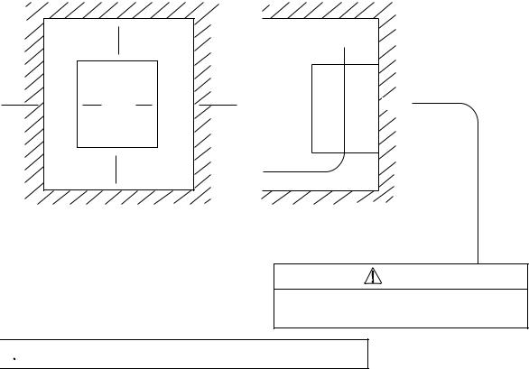
For cooling purposes, be sure that the inverter is installed vertically. In addition, be sure that it is separated from other components and walls. If foreign matter is introduced into the interior of the inverter, this may cause malfunctions, so make sure that no foreign matter can enter it.
5 cm
or more
|
10 cm or more |
|
|
|
(30cm or more) |
|
|
|
|
||
|
|
5 cm |
|
|
|
or |
|
|
|
more |
|
|
|
|
|
|
10 cm or more |
|
|
|
|
(30cm or more) |
|
|
|
|
|
Flow of air
Wall |
|
|
(a) (b)
NOTE: Install the inverter vertically.
Do not install it on the floor or horizontally.
( ) is for 75 to 260kW
CAUTION
Be sure that the wall surface is a nonflammable material, such as steel plate.

 Be sure to check the ambient temperature.
Place of installation |
Load characteristics |
Ambient temperature |
Applicable model |
|
|
|
|
Within the enclosure |
Constant torque |
-10 to 50°C |
All models |
(NOTE 1) |
Variable torque |
-10 to 40°C |
(NOTE 2) |
|
|
|
|
|
|
|
|
|
|
|
|
NOTE 1: The inverter should be installed in a locked enclosure that meets the requirements in IP4X.
The higher the ambient temperature inside the inverter, the shorter its life will be. If a heat generating unit is used near the inverter, try to keep it as far away as possible. Also, when installing the inverter in a box, be sure to carefully consider ventilation and the dimensions.
NOTE 2: Each of inverters 22 kW to 260 kW must be installed in a locked enclosure.
4-2
Phone: 800.894.0412 - Fax: 888.723.4773 - Web: www.clrwtr.com - Email: info@clrwtr.com
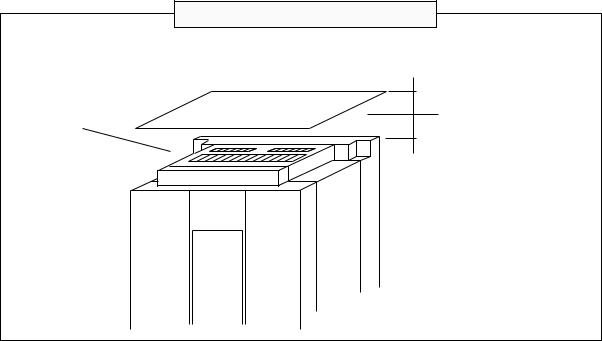
Precaution for installation and wiring
When executing the wiring work or another work, attach a cover on the vent hole (slit) on the top of the inverter to prevent wire chips, weld spatters, iron scraps, or dust from falling into the inverter.
Vent hole
15 cm or more
Cover (a nonflammable plate such as an iron plate)
4-3
Phone: 800.894.0412 - Fax: 888.723.4773 - Web: www.clrwtr.com - Email: info@clrwtr.com
5. WIRING
 WARNING
*Be sure to ground the unit.
Otherwise, there is a danger of electric shock and/or fire.
*Wiring work shall be carried out by electrical experts. Otherwise, there is a danger of electric shock and/or fire.
*Implement wiring after checking that the power supply is off. It might incur electric shock and/or fire.
*After installing the main body, carry out wiring. Otherwise, there is a danger of electric shock and/or injury.
5-1
Phone: 800.894.0412 - Fax: 888.723.4773 - Web: www.clrwtr.com - Email: info@clrwtr.com

 CAUTION
*Make sure that the input voltage is:
Three phase 200 to 220 V/50 Hz, 200 to 230 V/60 Hz
Three phase 380 to 415 V/50 Hz, 400 to 460 V/60 Hz
*Be sure not to input a single phase to a 3 phase type. Otherwise, there is a danger of fire.
*Be sure not to connect AC power supply to the output terminals [U (T1), V (T2), W (T3)].
Otherwise, there is a danger of injury and/or fire.
|
|
INPUT |
OUTPUT |
||||
Note) |
|
|
|
|
|
|
|
(L1) |
(L2) |
(L3) |
(T1) |
(T2) (T3) |
|||
R |
S |
T |
U |
V W |
|||
|
|
|
|
|
|
|
|
Power supply
*Fasten the screws with the specified fastening torque. Check so that there is no loosening of screws.
Otherwise, there is a danger of fire.
Be sure to install an earth leakage breaker.
*The ground fault protection is designed to detect current flowing to the ground upon power on. This function is to protect the inverter,not people. Install the earth leakage breaker to protect against the ground fault on wires between the inverter and the motor. (Use a breaker that is very sensitive to high frequency current so as not to cause malfunction.)
*Be sure to set the fuse(s) (the same phase as the main power supply) in the operation circuit.
Otherwise, there is a danger of fire.
As for motor leads, earth leakage breakers and electromagnetic contactors, be sure to use the equivalent ones with the specified capacity (rated).
Otherwise, there is a danger of fire.
5-2
Phone: 800.894.0412 - Fax: 888.723.4773 - Web: www.clrwtr.com - Email: info@clrwtr.com
The terminal board will be exposed when the front cover or terminal cover (450L/HF, 550L/HF) is removed. Wire the inverter in this state.
5.1Wiring the Power Supply and Motor
G |
R |
S |
T RB P |
N |
U V |
W G |
(PE) |
(L1) |
(L2) |
(L3) (RB) (+) |
(-) |
(T1) (T2) |
(T3) (PE) |
MOTOR
Dynamic
braking
resistor
Braking Units
ELB
Power supply
•The inverter will be damaged if the power supply is connected to the motor terminals U(T1), V(T2) and W(T3), so be sure not to make any mistakes.
•If multiple motors are to be connected, be sure to attach a thermal relay to each motor.
NOTE 1: When changing the power supply of the motor between the inverter and commercial power, be sure to install mechanically interlocked switches Mg1 and Mg2.
|
|
|
|
Mg1 |
|
|
ELB |
|
|
|
|
Power |
R (L1) |
(T1) |
U |
|
|
S (L2) |
Inverter (T2) |
V |
Motor |
||
supply |
T (L3) |
(T3) W |
|||
Mg2 |
|||||
|
Mg0 |
|
|
||
|
|
|
|
||
NOTE 2: Install an earth leakage breaker at the input of the inverter. (Select an earth leakage breaker whose sensitive current level is raised in high frequency range.) When the cable length between the inverter and motor is long (more than 10 m), the thermal relay may malfunction due to higher harmonics. Therefore, install an AC reactor on the output side of the inverter or use a current sensor in place of the thermal relay.
5-3
Phone: 800.894.0412 - Fax: 888.723.4773 - Web: www.clrwtr.com - Email: info@clrwtr.com
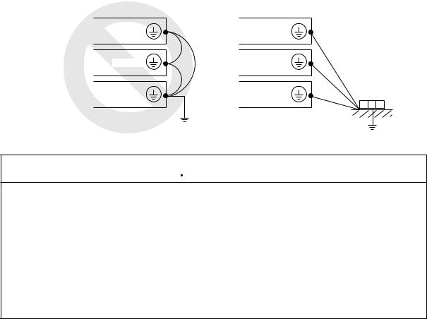
NOTE 3: Be sure that the specified grounding is carried out. Be sure to separate the unit’s grounding pole from those of other heavy electric machinery, and avoid using common grounding poles.
If multiple inverters are used, make sure that the grounding connections do not create a loop.
Improper grounding |
Proper grounding |
|
Inverter |
Inverter |
|
Inverter |
Inverter |
|
|
|
Grounding bolt |
Inverter |
Inverter |
(at the site) |
|
 CAUTION
External or remote over load protection required, if multiple motors to be connected.
For models J300-450LFU and -550LFU only , connect to branch circuit protected at maximum 300% of output current rating.
Suitable for use on a circuit capable of delivering not more than 10,000 rms symmetrical amperes,*** volts maximum,
(where *** = input voltage)
5-4
Phone: 800.894.0412 - Fax: 888.723.4773 - Web: www.clrwtr.com - Email: info@clrwtr.com
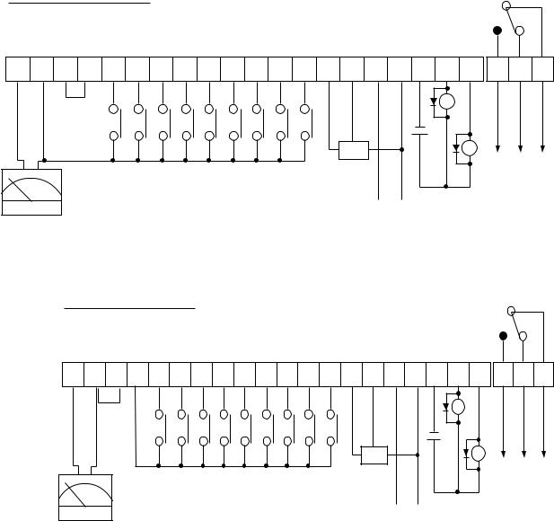
5.2Wiring of Control Circuit Terminals
SINK TYPE wiring
(Factory settings)
FM CM1 PLC P24 FW 8 7 6 5 4 3 2 1 H O OI L CM2 12 11 AL2 AL1 AL0
Input intelligent terminal
Frequency meter
|
RY |
|
RY |
|
Fault alarm |
Frequency setting |
|
(500 |
Ω to 2 kΩ) |
|
For output |
|
Current input |
Intelligent terminal |
|
27 VDC 50 mA |
||
DC 4 to 20 mA |
||
50 mA max |
||
|
SOURCE TYPE wiring
FM CM1 PLC P24 FW 8 7 6 5 4 3 2 1 H O OI L CM2 12 11 AL2 AL1 AL0
Input intelligent terminal
Frequency meter
|
RY |
|
RY |
|
Fault alarm |
Frequency setting |
|
(500 |
Ω to 2 kΩ) |
|
For output |
|
Current input |
Intelligent terminal |
|
27 VDC 50 mA |
||
DC 4 to 20 mA |
||
50 mA max |
||
|
NOTE 1: When an output intelligent terminal is used, be sure to install a surge absorbing diode in parallel with the relay (RY). Otherwise, the surge voltage created when the relay (RY) goes ON or OFF may damage the output intelligent terminal circuit.
NOTE 2: Use a twisted and shielded wire for the signal line, and cut the shielded covering as shown in the diagram below. Make sure that the length of the signal line is 20 meters or less.
5-5
Phone: 800.894.0412 - Fax: 888.723.4773 - Web: www.clrwtr.com - Email: info@clrwtr.com
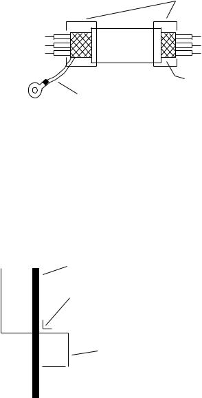
Insulate
No grounding necessary Connect FG (frame ground) of the inverter.
NOTE 3: When the frequency setting signal is turned on and off with a contact, use a relay which will not cause contact malfunctions, even with the extremely weak currents and voltages, such as crossbar twin contacts, etc.
NOTE 4: Use relays which do not have contact defects at 24 V DC, 3 mA for the other terminals.
NOTE 5: Separate the main circuit wiring from the relay control circuit wiring. If they must cross, be sure that they cross at a right angle.
Main circuit power line
(R, S, T, U, V, W, PP, P, RB, N, L1, L2, L3, T1, T2, T3, +, -, etc.)
Right angle
Signal input line
(FM, CM1, PLC, P24, FW, 8, 7, 6, 5, 4, 3, 2, 1, H, O, OI, L, CM2, 12, 11, AL0, AL1, AL2)
Separate by 10 cm or more.
NOTE 6: Do not short between the terminals H and L and between the terminals P24 and CM1 of the control circuit.
NOTE 7: Insulate the common terminal L for frequency analog command input and the common terminal (COMMON) of the peripheral equipment such as the sequencer before starting use.
5-6
Phone: 800.894.0412 - Fax: 888.723.4773 - Web: www.clrwtr.com - Email: info@clrwtr.com
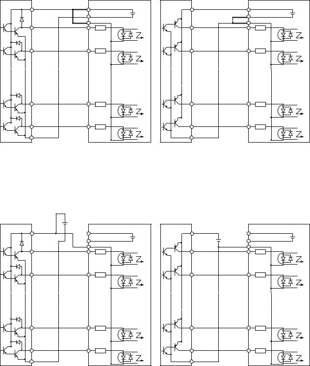
5.3Connection to the Programmable Controller
(1)When the internal interface power source is used
This is an example when the sink type transistor output (open collector output) module of the sequencer is connected
Note: Make sure of the short-circuit bar or wire between the terminals PLC and P24.
|
|
J300 series |
S |
P24 |
+ |
|
CM1 |
|
|
24V DC |
|
|
PLC |
- |
1 |
|
|
|
|
|
|
FW |
|
2 |
8 |
|
8 |
2 |
|
9 |
1 |
|
COM |
|
|
YTR48 type output module |
|
Inverter |
(by Hitachi) |
|
|
This is an example when the source type transistor output (open collector output) module of the sequencer is connected
Note: Make sure of the short-circuit bar or wire between the terminals CM1 and PLC.
|
|
J300 series |
COM |
P24 |
+ |
|
CM1 |
|
|
24V DC |
|
|
PLC |
- |
1 |
|
|
|
|
|
|
FW |
|
2 |
8 |
|
8 |
2 |
|
9 |
1 |
|
S |
|
|
YTS48 type output module |
|
Inverter |
(by Hitachi) |
|
|
(2) When the external interface power source is used
This is an example when the sink type transistor output (open collector output) module of the sequencer is connected
Note: Remove the short-circuit bar or wire between the terminals CM1 and PLC or P24 and PLC.
This is an example when the source type transistor output (open collector output) module of the sequencer is connected
Note: Remove the short-circuit bar or wire between the terminals CM1 and PLC or P24 and PLC.
|
+ |
|
J300 series |
|
24V DC |
|
|
S |
- |
P24 |
+ |
|
|||
|
|
CM1 |
|
|
|
24V DC |
|
|
|
PLC |
- |
1 |
|
|
|
|
|
|
|
|
|
FW |
|
2 |
|
8 |
|
8 |
|
2 |
|
9 |
|
1 |
|
|
COM |
|
|
YTR48 type output module |
|
Inverter |
|
(by Hitachi) |
|
|
|
|
|
J300 series |
|
COM |
P24 |
+ |
|
+ |
CM1 |
||
24V DC |
|||
24V DC |
|||
- |
|||
- |
PLC |
||
1 |
|
|
|
|
FW |
|
|
2 |
8 |
|
|
8 |
2 |
|
|
9 |
1 |
|
|
S |
|
|
|
YTS48 type output module |
|
Inverter |
|
(by Hitachi) |
|
|
Note: Be sure to turn the inverter on after the controller and external power source are turned on. (Otherwise, the data in the inverter may be changed.)
5-7
Phone: 800.894.0412 - Fax: 888.723.4773 - Web: www.clrwtr.com - Email: info@clrwtr.com
5.4Wiring Equipment, Options (EMI filter, etc.)
Standard equipment
Power supply
ELB
Magnetic
contactor |
|
|
(200V class)
|
|
|
Wiring (AWG or Kcmil) |
|
|
Applicable equipment |
||||
|
|
|
|
|
|
|
|
|
|
|
Inverter |
Constant torqe |
Variable torqe |
Power |
|
Signal |
Signal |
Earth leakage |
Electro- |
||
|
|
|
|
lines |
|
lines |
lines |
breaker (ELB) |
magnetic |
|
model |
Motor |
Power |
Motor |
Power |
External |
FM,CM1,PCL |
P24,AL0,AL1 |
|
contactor |
|
|
output |
lines |
output |
lines |
resistor |
|
FW,8,7,6,5,4,3 |
AL2 |
|
|
|
(kW) |
R,S,T,U,V |
(kW) |
R,S,T,U,V |
RB1,2,3, |
|
2,1,H,O,OL,L, |
|
|
|
|
W,P,N |
W,P,N |
P,RB |
|
CM2,12,11 |
|
|
|
||
|
|
|
|
|
|
|
|
|||
J300-055LF |
5.5 |
AWG 8 |
7.5 |
AWG 8 |
10 |
|
AWG 18 |
AWG 16 |
EX50C(30A) |
H20 |
or more |
or more |
or more |
|
Shielded |
or more |
|||||
|
|
|
|
|
|
|||||
J300-075LF |
7.5 |
AWG 6 |
11 |
AWG 6 |
10 |
|
wire |
|
EX50C(30A) |
H20 |
or more |
or more |
|
|
|||||||
or more |
|
|
|
|||||||
|
|
|
|
|
|
|
|
|||
J300-110LF |
11 |
AWG 4 |
15 |
AWG 4 |
|
|
|
|
EX50C(50A) |
H25 |
or more |
or more |
|
|
When the |
|
|||||
|
|
|
|
|
|
|
|
|||
J300-150LF |
15 |
AWG 3 |
22 |
AWG 3 |
|
|
number of |
|
EX60B(60A) |
H35 |
or more |
or more |
|
|
shielded |
|
|||||
|
|
|
|
|
wires to be |
|
|
|
||
J300-220LF |
22 |
AWG 1/0 |
30 |
AWG 1/0 |
|
|
used is 11 |
|
RX100(75A) |
H50 |
or more |
or more |
|
|
or more, |
|
|||||
|
|
|
|
|
the section |
|
|
|
||
J300-300LF |
30 |
AWG 3/0 |
37 |
AWG 3/0 |
|
|
of each |
|
RX100(100A) |
H65 |
or more |
or more |
|
|
shielded |
|
|||||
|
|
|
|
|
wire |
|
|
|
||
|
|
AWG 4/0 |
|
AWG 4/0 |
|
|
|
|
|
|
J300-370LF |
37 |
45 |
|
|
should be |
|
RX100(100A) |
H80 |
||
or more |
or more |
|
|
AWG 20 |
|
|||||
|
|
|
|
|
|
|
|
|
||
J300-450LF |
45 |
300 |
55 |
300 |
|
|
|
|
RX225(150A) |
H100 |
or more |
or more |
|
|
|
|
|||||
|
|
|
|
|
|
|
|
|
||
J300-550LF |
55 |
350 |
75 |
350 |
|
|
|
|
RX225(175A) |
H125 |
or more |
or more |
|
|
|
|
|||||
|
|
|
|
|
|
|
|
|
||
|
|
|
|
|
|
|
|
|
|
|
(400V class)
|
|
|
|
|
Wiring |
|
|
|
|
|
|
Applicable equipment |
|
|
|
|
|
|
|
|
|
|
|
|
|
||
|
Inverter |
Constant torqe |
Variable torqe |
Power |
|
Signal |
Signal |
Earth leakage |
Electro- |
||||
|
|
|
|
|
lines |
|
lines |
lines |
breaker (ELB) |
magnetic |
|||
|
Motor |
Power |
Motor |
Power |
|
||||||||
|
model |
External FM,CM1,PCL P24,AL0,AL1 |
|
contactor |
|||||||||
|
|
output |
lines |
output |
lines |
resistor |
|
FW,8,7,6,5,4,3 AL2 |
|
|
|||
|
|
(kW) |
R,S,T,U,V |
(kW) |
R,S,T,U,V |
RB1,2,3, |
|
2,1,H,O,OL,L, |
|
|
|
|
|
|
|
W,P,N |
W,P,N |
P,RB |
|
CM2,12,11 |
|
|
|
|
|||
|
|
|
|
|
|
|
|
|
|
||||
|
J300-055HF |
5.5 |
AWG 8 |
7.5 |
AWG 8 |
10 |
|
AWG 18 |
AWG 16 |
EX50C(30A) |
H20 |
||
|
|
or more |
|
||||||||||
|
or more |
or more |
Shielded |
or more |
|||||||||
|
|
|
|
|
|
||||||||
|
J300-075HF |
7.5 |
AWG 8 |
11 |
AWG 8 |
10 |
|
wire |
|
|
EX50C(30A) |
H20 |
|
|
or more |
or more |
or more |
|
|
|
|
||||||
|
|
|
|
|
|
|
|
|
|
||||
|
J300-110HF |
11 |
AWG 8 |
15 |
AWG 8 |
|
|
|
|
|
|
EX50C(50A) |
H25 |
|
or more |
or more |
|
|
|
When the |
|
|
|||||
|
|
|
|
|
|
|
|
|
|
|
|||
|
J300-150HF |
15 |
AWG 6 |
22 |
AWG 6 |
|
|
|
number of |
|
|
EX60B(60A) |
H35 |
|
or more |
or more |
|
|
|
shielded |
|
|
|||||
|
|
|
|
|
|
|
wires to be |
|
|
|
|
||
|
J300-220HF |
22 |
AWG 4 |
30 |
AWG 4 |
|
|
|
used is 11 |
|
|
RX100(75A) |
H50 |
|
or more |
or more |
|
|
|
or more, |
|
|
|||||
|
|
|
|
|
|
|
the section |
|
|
|
|
||
|
J300-300HF |
30 |
AWG 4 |
37 |
AWG 4 |
|
|
|
of each |
|
|
RX100(100A) |
H65 |
|
or more |
or more |
|
|
|
shielded |
|
|
|||||
|
|
|
|
|
|
|
wire |
|
|
|
|
||
|
|
|
AWG 2 |
|
AWG 2 |
|
|
|
|
|
|
|
|
|
J300-370HF |
37 |
45 |
|
|
|
should be |
|
|
RX100(100A) |
H80 |
||
|
or more |
or more |
|
|
|
AWG 20. |
|
|
|||||
|
|
|
|
|
|
|
|
|
|
|
|||
|
J300-450HF |
45 |
AWG 1 |
55 |
AWG 1 |
|
|
|
|
|
|
RX225(150A) |
H100 |
|
or more |
or more |
|
|
|
|
|
|
|||||
|
|
|
|
|
|
|
|
|
|
|
|
||
|
J300-550HF |
55 |
AWG 3/0 |
75 |
AWG 3/0 |
|
|
|
|
|
|
RX225(175A) |
H125 |
|
or more |
or more |
|
|
|
|
|
|
|||||
|
|
|
|
|
|
|
|
|
|
|
|
||
|
J300-750HF |
75 |
300 |
90 |
300 |
|
|
|
|
|
|
RX225(225A) |
H150 |
|
or more |
or more |
|
|
|
|
|
|
|||||
|
|
|
|
|
|
|
|
|
|
|
|
||
|
J300-900HF |
90 |
300 |
110 |
300 |
|
|
|
|
|
|
RX225(250A) |
H220 |
|
or more |
or more |
|
|
|
|
|
|
|||||
|
|
|
|
|
|
|
|
|
|
|
|
||
|
|
|
|
|
|
|
|
|
|
|
|
|
|
|
J300-1100HF |
110 |
350 |
132 |
350 |
|
|
|
|
|
|
RX400(350A) |
H250 |
|
or more |
or more |
|
|
|
|
|
|
|||||
|
|
|
|
|
|
|
|
|
|
|
|
||
|
|
|
|
|
|
|
|
|
|
|
|
|
|
|
J300-1320HF |
132 |
AWG 4 / 0 |
160 |
AWG 4 / 0 |
|
|
|
|
|
|
RX400(400A) |
H400 |
|
parallel |
|
|
|
|
|
|
||||||
|
|
|
|
parallel |
|
|
|
|
|
|
|
|
|
|
J300-1600HF |
160 |
300 |
220 |
300 |
|
|
|
|
|
|
RX600(600A) |
H600 |
|
parallel |
|
|
|
|
|
|
||||||
|
|
|
|
parallel |
|
|
|
|
|
|
|
|
|
|
|
|
|
|
|
|
|
|
|
|
|
|
|
|
J300-2200HF |
220 |
350 |
260 |
350 |
|
|
|
|
|
|
RX600(600A) |
H600 |
|
parallel |
|
|
|
|
|
|
||||||
|
|
|
|
parallel |
|
|
|
|
|
|
|
|
|
5-8
Phone: 800.894.0412 - Fax: 888.723.4773 - Web: www.clrwtr.com - Email: info@clrwtr.com
R S T (L1) (L2) (L3)
(+) P 
Inverter
RB 
(T1) (T2) (T3)
U V W
Thermal relay
Motor
IM
|
|
|
|
|
|
Part description |
Function |
|
|
|
|
|
|
|
|||
|
|
|
|
|
|
AC reactor for |
This part is used when the unbalance voltage ratio is 3% |
|
|
|
|
|
|
|
improving |
|
or more and power supply is 500 kVA or more, and there |
|
|
|
|
|
|
|
||
|
|
|
|
|
|
the power factor |
is a rapid change in the power supply. |
|
|
|
|
|
|
|
(ALI- |
L) |
It also improves the power factor. |
|
|
|
|
|
|
(ALI- |
H) |
|
|
|
|
|
|
|
|
|
|
|
|
|
|
|
|
Radio noise filter |
Using the inverter may cause noise on the peripheral |
|
|
|
|
|
|
|
|||
|
|
|
|
|
|
(Zero phase |
equipment through the power lines. |
|
|
|
|
|
|
|
reactor) (ZCL-A) |
This part reduces noise. |
|
|
|
|
|
|
|
|
|
|
|
|
|
|
|
|
EMI filter for |
This part reduces common noise generated between |
|
|
|
|
|
|
|
|||
|
|
|
|
|
|
inverter |
|
the power supply and the ground, as well as normal noise. |
|
|
|
|
|
|
(FFJ300- |
) |
Put it in the primary side of inverter. |
|
|
|
|
|
|
|
|
|
|
|
|
|
|
|
Regenerative |
This part is used for applications that needs to increase |
|
|
|
|
|
|
|
resistor |
|
the brake torque of the inverter or to frequently turn on |
|
|
|
|
|
|
|
||
|
|
|
|
|
|
(RB |
- ) |
and off and to run high inertia load. |
|
|
|
|
|
|
|
|
|
|
|
|
|
|
|
Radio noise filter |
This part reduces noise generated at the output of |
|
|
|
|
|
|
|
(Zero phase |
the inverter. |
|
|
|
|
|
|
|
reactor) (ZCL-A) |
(It is possible to use for both input and output.) |
|
|
|
|
|
|
|
|
|
|
|
|
|
|
|
|
|
|
|
|
|
|
|
|
|
AC reactor for |
Running motors with the inverter generates vibration |
|
|
|
|
|
|
|
reducing vibration |
greater than that with commercial power supply. |
|
|
|
|
|
|
|
(ACL-L- |
) |
This part installed between the inverter and motor reduces |
|
|
|
|
|
|
(ACL-H- |
) |
torque ripple. |
|
|
|
|
|
|
|||
|
|
|
|
|
|
|
|
When the cable length between the inverter and motor is |
|
|
|
|
|
|
|
|
long, a countermeasure for a malfunction of the termal |
|
|
|
|
|
|
|
|
relay is taken. |
|
|
|
|
|
|
|
|
|
NOTE 1: The applicable equipment is for Hitachi standard four pole squirrel-cage motor NOTE 2: Be sure to consider the capacity of the circuit breaker to be used.
NOTE 3: Be sure to use bigger wires for power lines if the distance exceeds 20m. NOTE 4: Be sure to use an grounding wire same size of power line or similar.
(*) Use AWG 16 wire for the alarm signal wire.
Classify the detective current of the earth leakage breaker depending on the total distance between the inverter and the motor.
length |
Detective current (mA) |
100 m and less |
30 |
300 m and less |
100 |
600 m and less |
200 |
NOTE 5: When using CV wire and metal tube, the leakage current is around 30 mA/km.
NOTE 6: The leakage current becomes eight times because IV wires have a high dielectric constant. Therefore, use an one class larger earth leakage breaker according to the left table.
5-9
Phone: 800.894.0412 - Fax: 888.723.4773 - Web: www.clrwtr.com - Email: info@clrwtr.com
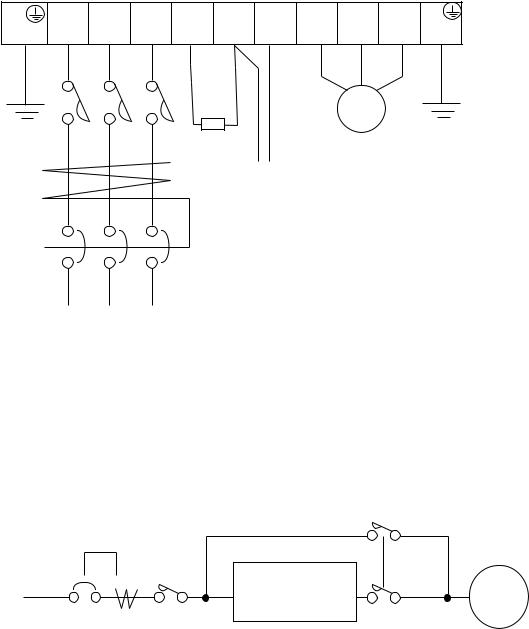
5.5Terminal
(1)Main circuit terminal
Terminal layout
|
Width |
|
|
|
|
||
Type |
Screw |
Width |
|
diameter |
(mm) |
||
|
G |
R |
S |
T RB P |
N |
U |
V W |
G |
|
055, 075LF |
M5 |
13 |
|
|||||||||
(PE) |
(L1) |
(L2) |
(L3) |
(RB) |
(+) |
|
(Ð) |
(T1) (T1) |
(T1) |
(PE) |
|
|
|||||||||
|
|
055,075HF |
|
||||||||||||||||||
|
|
|
|
|
|
|
|
|
|
|
|
|
|
|
|
|
|
|
|
|
|
|
|
|
|
|
|
|
|
|
|
|
|
|
|
|
|
|
|
011, 150LF |
M6 |
17.5 |
|
G |
R |
S |
T |
|
P |
|
|
N |
U |
V |
W |
G |
|
|
011, 150HF |
|
|
|
|||
(PE) |
(L1) |
(L2) |
(L3) |
(+) |
|
|
(Ð) |
(T1) |
(T1) |
(T1) |
(PE) |
|
|
220 to 370LF |
M8 |
23 |
|
||||
|
|
|
|
|
|
|
|
|
|
|
|
|
|
|
|
|
|
450, 550LF |
M10 |
35 |
|
|
|
|
|
|
|
|
|
|
|
|
|
Internal short circuit bar |
G |
|
220 to 370HF |
M6 |
17.5 |
|
|||
|
|
|
|
|
|
|
|
|
|
|
|
|
|
||||||||
G |
R |
S |
T PD P |
N |
U |
V W |
|
|
|
|
|
||||||||||
|
450, 550HF |
M8 |
23 |
|
|||||||||||||||||
(PE) |
(L1) |
(L2) |
(L3) |
(+1) |
(+) |
|
(Ð) |
(T1) |
(T1) |
(T1) |
(PE) |
|
|
||||||||
|
|
|
|
|
|
|
|
|
|
|
|
Internal short circuit bar |
|
|
750, 900HF |
M10 |
35 |
|
|||
|
|
|
|
|
|
|
|
|
|
|
|
|
|
|
|
|
|
||||
G |
R |
S |
T |
|
PD |
|
|
P |
N |
U |
V |
W |
G |
|
1100HF |
M10 |
40 |
|
|||
(PE) |
(L1) |
(L2) |
(L3) |
(+1) |
(+) |
|
(Ð) |
(T1) |
(T1) |
(T1) |
(PE) |
|
|
|
|
|
|||||
|
1320 to 2200HF |
M16 |
51 |
|
|||||||||||||||||
|
|
|
|
|
|
|
|
|
|
|
|
|
|
|
|
|
|
||||
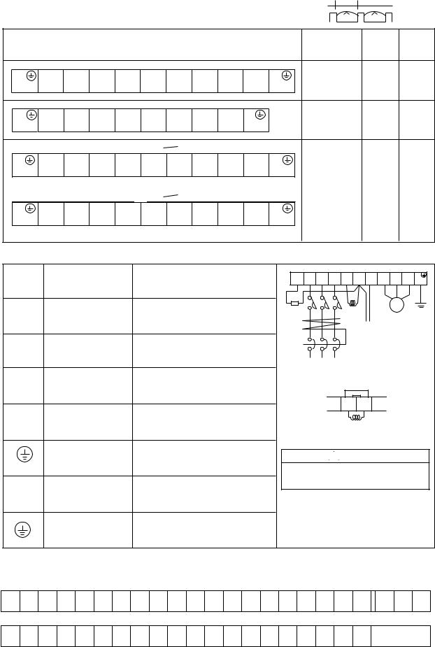
Main circuit
Terminal |
Terminal description |
|
symbol |
||
|
R, S, T
Main power
(L1),(L2),(L3)
U, V, W
Inverter output
(T1),(T2),(T3)
P, RB External braking
(+),(RB) resistor
Function
Connect the power supply
Connect the motor
Connect a braking resistor (option)
*Only the 055LF/HF and 075LF/HF are equipped RB terminals .
RB R |
S |
T PD P |
N |
U V |
W G |
(RB) (L1) |
(L2) |
(L3) (+1) (+) |
(-) |
(T1) (T2) |
(T3) (PE) |
Braking |
|
DCL |
|
MOTOR |
|
|
|
|
|
||
resistor |
|
|
|
|
|
|
|
Braking Units |
|
||
ELB
Power supply
Internal short circuit bar
PD P (+1) (+)
P, N |
Dynamic braking unit Connect a dynamic braking unit |
||
(+),(-) |
|
(option) |
|
G |
Ground |
Ground (connect grounding to avoid |
|
|
electric shock) |
||
(PE) |
|
||
|
|
||
PD |
External choke coil |
Connect a choke coil (DCL) for |
|
(+1) |
harmonics current reduction |
||
|
|||
Ground at case |
Ground (connect grounding to avoid |
|
electric shock) |
||
|
DCL
Remove the internal short circuit bar when DCL is connected.
 WARNING
Wait until DC bus voltage is discharged after power supply is turned off.
Otherwise, there is a danger of electric shock.
(2)Control circuit terminal
The intelligent I/O terminals 1 to 8 and 11 and 12 are initialized as shown below at factory before shipment.
FM |
CM1 PLC |
P24 |
FW |
REV CF1 |
USP CH1 FRS |
JG |
AT |
RS |
H |
O |
OI |
L |
CM2 RUN |
FA1 |
AL2 |
AL1 AL0 |
||||
|
|
|
|
− |
− |
− |
− |
− |
− |
− |
− |
|
|
|
|
− |
− |
|
|
|
|
|
|
|
|
|
|
|
|
|
|
|
|
|
|
|
|
|
|
|
|
FM |
CM1 PLC |
P24 |
FW |
8 |
7 |
6 |
5 |
4 |
3 |
2 |
1 |
H |
O |
OI |
L |
CM2 12 |
11 |
AL2 |
AL1 |
AL0 |
|
|
|
|
|
|
|
|
|
|
|
|
|
|
|
|
|
|
|
|
|
5-10
Phone: 800.894.0412 - Fax: 888.723.4773 - Web: www.clrwtr.com - Email: info@clrwtr.com
 Loading...