


JIG SAW
STICHSÄGE
SCIE SAUTEUSE
SEGHETTO ALTERNATIVO
DECOUPEERZAAGMACHINE
SIERRA CALADORA
FCJ 55VA • FCJ 55
FCJ 55
Read through carefully and understand these instructions before use.
Diese Anleitung vor Benutzung des Werkzeugs sorgfältig durchlesen und verstehen. Lire soigneusement et bien assimiler ces instructions avant usage.
Prima dell’uso leggere attentamente e comprendera queste istruzioni. Deze gebruiksaanwijzing s.v.p. voor gebruik zorgvuldig doorlezen. Leer cuidadosamente y comprender estas instrucciones antes del uso.
Handling instructions
Bedienungsanleitung
Mode d’emploi
Istruzioni per l’uso
Gebruiksaanwijzing
Instrucciones de manejo

|
Item No. |
Stator34 |
Internal35Wire(A) |
Internal36Wire |
Internal37Wire |
Internal38Wire(A) |
BarHex.501Wrench3mm |
SawJig502BladesNo.31 |
Splinter503Guard |
arePartssubject to possible |
modificationwithoutnoticedueto |
improvements. |
drawingTheandthelistareparts |
drawingstructuralandpartslistof FCJ55VA.model |
FCJ55modelFor refertothedrawing |
list.theand |
|
NamePart |
|
|
|
|
|
|
|
|
|
|
|
|
|
|
|
|
|
|
|
|
|
|
|
|
|
|
|
|
|
|
|
|
|
|
|
|
|
|
|
|
|
|
|
|
|
|
|
|
|
FCJ55VA |
Item No. |
CoverChip1 |
Housing2 (A).(B)Set |
(D)Tube3 |
Switch4 |
(D)Tube5 |
TerminalEarth6 |
Noise7Suppressor |
Connector8 (50091) |
Tapping9 Screw(W/Flange) |
D4×20 |
Name10Plate |
HITACHI11Label |
Carbon12Brush |
Brush13Holder |
ArmorCord14 Cord15 ClipCord16 Tapping17Screw(W/Flange) D4×16 NutPlate18 SocketHex.19 Hd.BoltM4×8 Base20 Guide21Roller LockerBase22 SocketHex.23 Hd.BoltM4×16 Metal24 Plunger25 RingSet26Ass’y Connecting27 Piece Gear28 Washer29(C) Holder30 BearingBall31 (608VVMC2EPS2L) Armature32 BearingBall33 (626VVMC2ERPS2S) |
|
NamePart |
|
|
|
|
|
|
|
|
|
|
|
|
|
|
|
|
|
|
|
|
|
|
|
|
|
|
|
|
|
|
|
|
FCJ55VA service center.
The exploded assembly drawing should be used only for authorized
1 |
2 |
1
4
0
5 3 2
3 |
|
4 |
7
8
6
9 0
5
3
A 2
1
7
8
D
6
C
B
8
B
C E
9 |
|
10 |
|
|
|
|
|
|
|
1
11 |
|
|
12 |
|
|
|
G |
|
|
|
|
|
F |
|
|
C |
|
|
B |
|
|||
|
|
|
C |
||
|
|
|
|
|
|
H8
13 I
|
English |
Deutsch |
Français |
1 |
Set ring |
Stellring |
Bague de réglage |
2 |
Hexagonal bar wrench |
Sechskantinnenschlüssel |
Clef à six pans |
3 |
Blade (blade edge must face |
Sägeblatt (Schnittfläche muß |
Lame (le bord de la lame doit être |
|
front) |
nach vorne zeigen) |
tourné vers l’avant) |
4 |
Blade set screw |
Klemmschraube für das Sägeblatt |
Vis de réglage de la lame |
5 |
Roller |
Führungsrolle |
Rouleau |
6 |
Holder |
Halter |
Support |
7 |
Housing |
Gehäuse |
Logement |
8 |
Base |
Sägetisch |
Base |
9 |
Base locker |
Sicherungsvorrichtung für den |
Section de blocage de la base |
Sägetisch |
|
||
|
|
|
|
0 |
4mm screw (16mm) |
4mm Schraube (16mm) |
Vis de 4mm (16mm) |
A |
Chip cover |
Schnipseldeckel |
Couvercle d’éclats |
B |
Guide |
Führungsrolle |
Guide |
C |
4mm screw (8mm) |
4mm Schraube (8mm) |
Vis de 4mm (8mm) |
D |
Splinter guard |
Splitterschutz |
Anti-éclats |
E |
Nail or wood screw |
Nagel oder Holzschraube |
Clou ou vis de bois |
F |
Scale |
Skala |
Echelle |
G |
Side groove |
Seitlicher Schlitz |
Fente latérale |
H |
Housing edge line |
Gehäusekante |
Arête du logement |
I |
Acceptable blades |
Verwendbare Sägeblätter |
Lames acceptables |
2
|
Italiano |
Nederlands |
Español |
|
1 |
Anello di fissaggio |
Stelring |
Anillo de ajuste |
|
2 |
Chiave maschia esagonale |
Inbussleutel |
Llave macho hexagonal |
|
3 |
Lama (il taglio della lama deve |
Zaagblad (snijkant moet naar |
Cuchilla (el filo tiene que mirar |
|
essererivolto in avanti) |
voren wijzen) |
hacia el frente) |
||
|
||||
4 |
Vite di fissaggio della lama |
Klemschroef |
Tornillo de ajuste de la cuchilla |
|
5 |
Rullo |
Geleiderol |
Rodillo |
|
6 |
Sostegno |
Houder |
Sujetador |
|
7 |
Involucro |
Behuizing |
Caja |
|
8 |
Base |
Zaagtafel |
Base |
|
9 |
Bloccaggio della base |
Veiligheidsinrichting voor de |
Gaveta de base |
|
zaagtafel |
||||
|
|
|
||
0 |
Vite da 4mm (16mm) |
4mm schroef (16mm) |
Tornillo 4mm (16mm) |
|
A |
Reccoglitrucioli |
Spaankast |
Cubierta de virutas |
|
B |
Guida |
Geleider |
Guía |
|
C |
Vite da 4mm (8mm) |
4mm schroef (8mm) |
Tornillo 4mm (8mm) |
|
D |
Para-schegge |
Anti-splinterstuk |
Protector contra astillas |
|
E |
Chiodo o vite del legno |
Spijker of houtschroef |
Clavo o tornillo para madera |
|
F |
Scala graduata |
Schaal |
Escala |
|
G |
Solco laterale |
Gleuf aan de zijkant |
Hueco lateral |
|
H |
Bordo dell’involucro |
Behuizingshoeklijn |
Extremo de la caja |
|
I |
Lama accettabile |
Te gebruiken zaagbladen |
Cuchillas aceptables |
3

English
GENERAL OPERATIONAL PRECAUTIONS
WARNING! When using electric tools, basic safety precautions should always be followed to reduce the risk of fire, electric shock and personal injury, including the following.
Read all these instructions before operating this product and save these instructions.
For safe operations:
1.Keep work area clean. Cluttered areas and benches invite injuries.
2.Consider work area environment. Do not expose power tools to rain. Do not use power tools in damp or wet locations. Keep work area well lit.
Do not use power tools where there is risk to cause fire or explosion.
3.Guard against electric shock. Avoid body contact with earthed or grounded surfaces. (e.g. pipes, radiators, ranges, refrigerators).
4.Keep children and infirm persons away. Do not let visitors touch the tool or extension cord. All visitors should be kept away from work area.
5.Store idle tools. When not in use, tools should be stored in a dry, high or locked up place, out of reach of children and infirm persons.
6.Do not force the tool. It will do the job better and safer at the rate for which it was intended.
7.Use the right tool. Do not force small tools or attachments to do the job of a heavy duty tool. Do not use tools for purposes not intended; for example, do not use circular saw to cut tree limbs or logs.
8.Dress properly. Do not wear loose clothing or jewelry, they can be caught in moving parts. Rubber gloves and non-skid footwear are recommended when working outdoors. Wear protecting hair covering to contain long hair.
9.Use eye protection. Also use face or dust mask if the cutting operation is dusty.
10.Connect dust extraction equipment.
If devices are provided for the connection of dust extraction and collection facilities ensure these are connected and properly used.
11.Do not abuse the cord. Never carry the tool by the cord or yank it to disconnect it from the receptacle. Keep the cord away from heat, oil and sharp edges.
12.Secure work. Use clamps or a vise to hold the work. It is safer than using your hand and it frees both hands to operate tool.
13.Do not overreach. Keep proper footing and balance at all times.
14.Maintain tools with care. Keep cutting tools sharp and clean for better and safer performance. Follow instructions for lubrication and changing accessories. Inspect tool cords periodically and if damaged, have it repaired by authorized service center. Inspect extension cords periodically and replace, if damaged. Keep handles dry, clean, and free from oil and grease.
15.Disconnect tools. When not in use, before servicing, and when changing accessories such as blades, bits and cutters.
16.Remove adjusting keys and wrenches. Form the habit of checking to see that keys and adjusting wrenches are removed from the tool before turning it on.
17.Avoid unintentional starting. Do not carry a pluggedin tool with a finger on the switch. Ensure switch is off when plugging in.
18.Use outdoor extension leads. When tool is used outdoors, use only extension cords intended for outdoor use.
19.Stay alert. Watch what you are doing. Use common sense. Do not operate tool when you are tired.
20.Check damaged parts. Before further use of the tool, a guard or other part that is damaged should be carefully checked to determine that it will operate properly and perform its intended function. Check for alignment of moving parts, free running of moving parts, breakage of parts, mounting and any other conditions that may affect its operation. A guard or other part that is damaged should be properly repaired or replaced by an authorized service center unless otherwise indicated in this handling instructions. Have defective switches replaced by an authorized service center. Do not use the tool if the switch does not turn it on and off.
21.Warning
The use of any accessory or attachment, other than those recommended in this handling instructions, may present a risk of personal injury.
22.Have your tool repaired by a qualified person. This electric tool is in accordance with the relevant safety requirements. Repairs should only be carried out by qualified persons using original spare parts. Otherwise this may result in considerable danger to the user.
4

|
|
|
|
|
English |
|
|
|
|
|
|
|
|
|
|
|
|
|
|
|
SPECIFICATIONS |
|
|
|
|
|
|
|
|
|
|
|
|
|
Model |
|
FCJ55VA |
|
|
FCJ55 |
|
Voltage (by areas)* |
|
(110V, 115V, 120V, 127V, 220V, 230V, 240V) |
|
|||
Power input |
|
|
400W* |
|
||
Max. cutting depth |
|
|
Wood: 55mm |
|
||
|
|
Mild steel: 3mm |
|
|||
|
|
|
|
|||
No-load speed |
|
0 ~ 3000/min |
|
3000/min |
|
|
Stroke |
|
|
18mm |
|
||
Min. cutting radius |
|
|
25mm |
|
||
Weight (without cord) |
|
|
1.4kg |
|
||
* Be sure to check the nameplate on product as it is subject to change by areas.
STANDARD ACCESSORIES |
|
|
(1) |
Blade No.31 ................................................................. |
1 |
|
For cutting thick lumber |
|
(2) |
Splinter guard ............................................................. |
1 |
(3) |
Chip cover ................................................................... |
1 |
(4) |
Hexagonal bar wrench ............................................... |
1 |
Standard accessories are subject to change without |
||
notice. |
|
|
OPTIONAL ACCESSORIES (sold separately)
(1)Blades, No.1 ~ No.6, 31*
*No.31 Blade is a standard accessory.
(2)Guide
(3)Dust collector
Optional accessories are subject to change without notice.
APPLICATIONS
Cutting various lumber and pocket cutting
Cutting mild steel plate, aluminum plate, and copper plate
Cutting synthetic resins, such as phenol resin and vinyl chloride
Cutting thin and soft construction materials
PRIOR TO OPERATION
1.Power source
Ensure that the power source to be utilized conforms to the power requirements specified on the product nameplate.
2.Power switch
Ensure that the power switch is in the OFF position. If the plug is connected to a receptacle while the power switch is in the ON position, the power tool will start operating immediately, which could cause a serious accident.
3.Extension cord
When the work area is removed from the power source, use an extension cord of sufficient thickness and rated capacity. The extension cord should be kept as short as practicable.
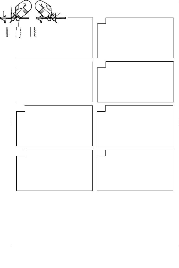
MOUNTING THE BLADE
1.Use the accessory hexagonal bar wrench to loosen the blade set screws on the set ring, as shown in
Fig. 1.
2.Holding the blade with its cutting edge facing the front, insert the mounting portion of the blade into the plunger groove until it touches the bottom of the groove.
3.As shown in Fig. 1, firmly clamp the side screw.
CAUTION
Loosened set screws may cause the blade to be damaged. Always ensure that the set screws are securely tightened. Always ensure that the plunger groove is clean and clear of sawdust to ensure proper blade mounting and set screw clamping.
ADJUSTING AND REMOVING THE GUIDE ROLLER
1.Adjusting the guide roller
The guide roller, shown in Fig. 2, is employed to prevent the blade from snapping. Prior to use, adjust guide roller in accordance with the following
procedures:
(1)Loosen the holder set screw with the accessory hexagonal bar wrench.
(2)Gently slide the guide roller until the roller groove lightly touches the back of the blade.
NOTE
On delivery from the factory, there is a gap of about 3mm between the roller and blade.
(3)Firmly tighten the holder set screw.
CAUTION
The guide roller can be used only for Blades that have a straight line on the rear that is longer than 50mm. (Fig. 3A and 3B) When using other types of blades (Fig. 3C), slide the guide roller in backwards so that the guide roller does not contact the blade.
When cutting thick boards or performing continuous cutting operations, use the blade shown in the Fig. 3A, 3B and be sure to set the guide roller.
2.Removing the guide roller
The guide roller can be removed from the jig saw as follows:
5

English
(1)Remove the 4mm screw, shown in Fig. 4, with the accessory hexagonal bar wrench, and remove the guide roller from the main body.
(2)To reassemble the main body and the base, insert the base locker between the base and the 4mm screw, as shown in Fig. 4, and securely clamp the 4mm screw.
CHIP COVER POSITIONING
1.Chip cover
Use the chip cover to reduce flying of cut particles and to easily operate the saw.
Slide the chip cover while lightly pressing its front section.
The chip cover can be set at three positions as shown in Fig. 5.
2.How to choose the position of the ship cover
Set the chip cover to the first step when attaching or removing the blade.
Set the chip cover to the second step when cutting wooden materials.
Set the chip cover to the second or third step when cutting metal materials such as steel.
CAUTION
Keep always the chip cover in the low position when operating the tool.
Wear protection glasses even if the chip cover is used.
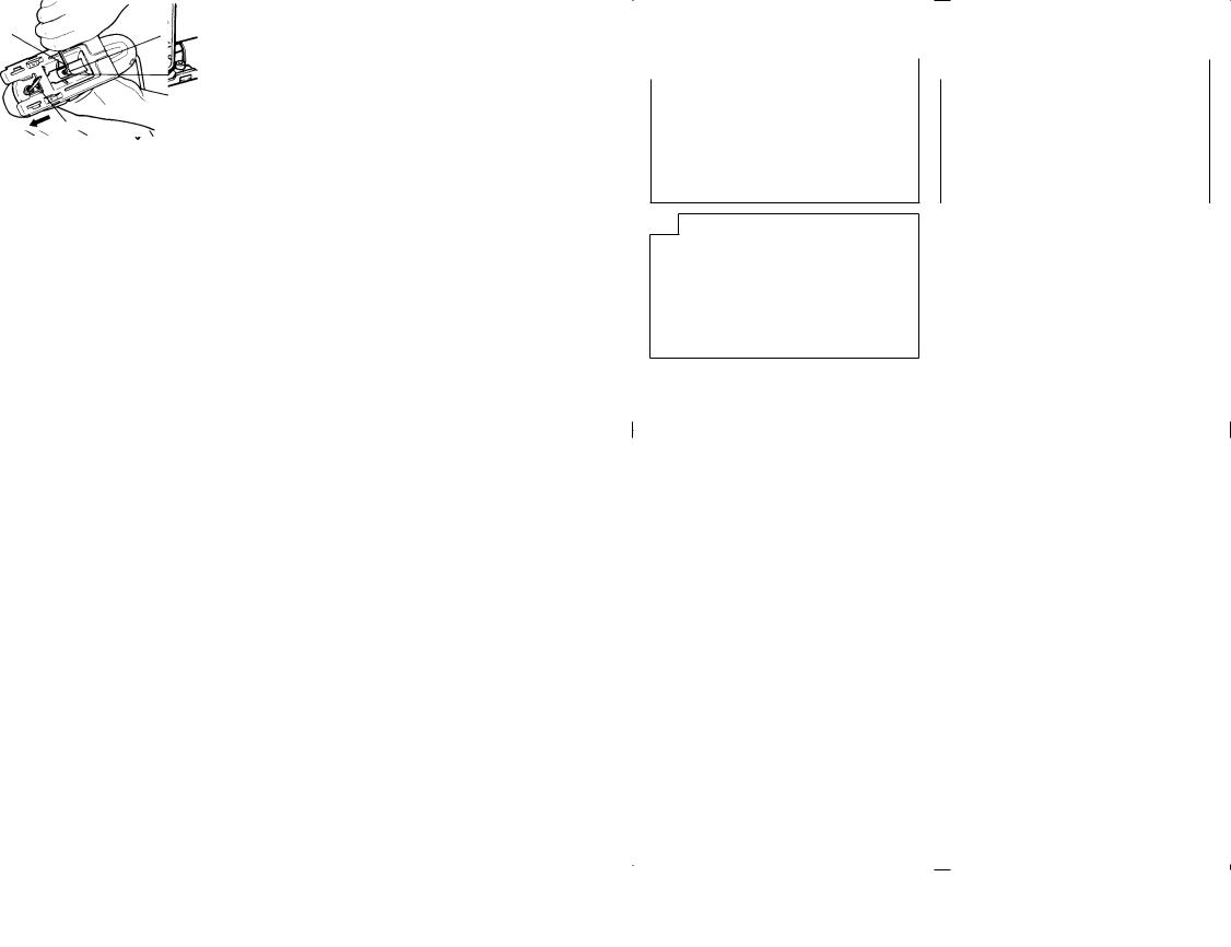
ADJUSTING THE BLADE OPERATING
SPEED .......................................... (FCJ55VA only)
NOTE
The blade operating speed cannot be adjusted for FCJ55.
The blade operating speed can be adjusted within a range of 0 to 3,000/min according to the degree that the trigger switch is depressed. Select the speed appropriate to the material being worked and/or the working conditions.
To achieve continuous operation, pull the trigger switch all the way back and depress the stopper. Then, turn the speed adjustment knob to adjust the blade operating speed as desired.
NOTE
The speed adjustment knob rotates approximately 3 turns. To turn the switch OFF, pull the trigger switch again to disengage the stopper, and release the trigger switch.
CUTTING
CAUTION
While sawing, the base must be firmly in contact with the material surface, and the blade must be held at a right angle. If the base becomes separated from the material, it could cause the blade to break.
When cutting while holding the front surface, be careful of the moving blade and hold the upper part firmly.
1. Rectilinear cutting
(1)To ensure accurate rectilinear cutting, employ the optional accessory guide as shown in Fig. 6.
(2)Use the splinter guard to reduce roughness of the cutting surface of wooden materials. Attach the splinter guard by inserting it from the front section of the base until it clicks into place. (Fig. 7)
CAUTION
Set the base in the front position when using the
splinter guard.
2.Cutting a circle or a circular arc
To ensure efficient cutting, employ the optional accessory guide and nail or wood screw as shown in
Fig. 8.
When mounting the guide, loosen the base bottom screw, and shift the base as far forward as it will go.
3.Sawing curved lines
When sawing a small circular arc, reduce the feeding speed of the machine. If the machine is fed too fast, it could cause the blade to break.
4.Cutting metallic materials
Always use an appropriate cutting agent (spindle oil, soapy water, etc.). When a liquid cutting agent is not available, apply grease to the back surface of the material to be cut.
5.Pocket cutting
(1)In lumber
Aligning the blade direction with the grain of the wood, cut step by step until a window hole is cut in the center of the lumber. (Fig. 9)
(2)In other materials
When cutting a window hole in materials other than lumber, initially bore a hole with a drill or similar tool
from which to start cutting.
6.Angular cutting
Set the chip cover to the first step. (Fig. 5)
To adjust the angle of inclination; loosen the base bottom screw, shift the base position to the side groove of the semicircular portion, align the scale on the base semicircular portion (figures engraved on the scale indicate the angle of inclination) with the housing edge line, and thoroughly tighten the base bottom screw. (Fig. 10 and 11)
CAUTION
Set the screw to the opposite side of the inclining side when using the guide. (Fig. 12)
SELECTION OF BLADES
1.Accessory blades
To ensure maximum operating efficiency and results it is very important to select the appropriate blade best suited to the type and thickness of the material to be cut. One type of blade is provided as standard accessory. The blade number is engraved in the vicinity of the mounting portion of each blade. Select appropriate blades by referring to Table 1.
2.Acceptable commercial blades (Fig. 13)
This machine is designed to accept most blades available on the open market. As illustrated in Fig. 13, blade dimension restrictions are as follows:
Thickness : |
L2 ..... |
Less than 1.6mm |
Width : |
L3 ..... |
6.3mm |
|
L4 ..... |
8mm |
|
L5 ..... |
7mm |
NOTE
When cutting thick materials, use HITACHI genuine blades which have an inclination as shown in Fig. 3-A or B.
6

|
|
|
English |
|
|
|
|
|
|
|
Table 1 List of Appropriate Blades |
|||
|
|
|
||
Material to be cut |
Material quality |
Blade No. |
|
|
Lumber |
General lumber |
No.1 or No.31 (thick plate) or No.2 (thin plate) |
|
|
Plywood |
No.3 or No.6 |
|
||
|
|
|||
Iron plate |
Mild steel plate |
No.6 |
|
|
Nonferrous metal |
Aluminum, copper, brass |
No.6 |
|
|
|
Phenol resin, melamine resin, etc. |
No.4 (thick plate) or No.6 (thin plate) |
|
|
Synthetic resin |
Vinyl chloride, acryl resin, etc. |
No.2 or No.4 (thick plate) or No.6 |
|
|
(thin plate) |
|
|||
|
|
|
||
|
Foamed styrol, etc. |
No.2 |
|
|
|
Cardboard, corrugated paper |
No.2 |
|
|
Pulp |
Hardboard |
No.5 or No.6 |
|
|
|
Fiberboard |
No.6 |
|
|
Others |
Hard rubber |
No.2 |
|
|
Slate |
No.5 |
|
||
|
|
|||
MAINTENANCE AND INSPECTION
1.Inspecting the blade
Continued use of a dull or damaged blade will result in reduced cutting efficiency and may cause overloading of the motor. Replace the blade with a new one as soon as excessive abrasion is noted.
2.Inspecting the mounting screws
Regularly inspect all mounting screws and ensure that they are properly tightened. Should any of the screws be loose, retighten them immediately. Failure to do so could result in serious hazard.
3.Maintenance of the motor
The motor unit winding is the very “heart” of the power tool. Exercise due care to ensure the winding does not become damaged and/or wet with oil or water.
4.Servicing
Consult an authorized Service Agent in the event of power tool failure.
NOTE
Due to HITACHI’s continuing program of research and development, the specifications herein are subject to change without prior notice.
IMPORTANT
Correct connection of the plug
The wires of the main lead are coloured in accordance with the following code:
Blue : –Neutral Brown : –Live
As the colours of the wires in the main lead of this tool may not correspond with the coloured markings identifying the terminals in your plug proceed as follows: The wire coloured blue must be connected to the terminal marked with the letter N or coloured black. The wire coloured brown must be connected to the terminal marked with the letter L or coloured red. Neither core must be connected to the earth terminal.
NOTE
This requirement is provided according to BRITISH STANDARD 2769: 1984
Therefore, the letter code and colour code may not be applicable to other markets except The United Kingdom.
Information concerning airborne noise and vibration
The measured values were determined according to EN50144.
The typical A-weighted sound pressure level: 81dB (A) Wear ear protection.
The typical weighted root mean square acceleration value: 6.5m/s2.
7
 Loading...