


 Loading...
 HITACHI AC SERVO DRIVES
With Programmable Functions(Enhancement)
ADAX4 Series
Instruction Manual
Thank you very much for purchasing the HITACHI AC servo drives.
This instruction manual describes the handling, maintenance, and others of the HITACHI AD series servo drives with AC servo programmable functions. Please read this manual thoroughly before operating it so that installation, maintenance, inspection may be performed correctly. For the program function, read the instruction manual pertaining to the Programmable Function.
When using option products related to this servo drives, read the instruction manuals for the related products thoroughly.
Keep this manual handy for your quick reference.
NB284X
SAFETY
SAFETY
For the Best Results with AD Series servo drives, read this manual and all of the warning sign attached to the servo drive carefully before installing and operating it, and follow the instructions exactly. Keep this manual handy for your quick reference.
Definitions and Symbols
A safety instruction (message) is given with a hazard alert symbol and a signal word;
WARNING or CAUTION. Each signal word has the following meaning throughout this manual.
This symbol means hazardous high voltage. It used to call your attention to items or operations that could be dangerous to you or other persons operating
|
this equipment. |
|
|
|
Read these message and follow these instructions carefully. |
||
|
This is the "Safety Alert Symbol" This symbol is used to call your attention |
||
|
to items or operations that could be dangerous to you or other persons |
||
|
operating this equipment. |
|
|
|
Read these messages and follow these instructions carefully. |
||
WARNING |
WARNING |
|
|
|
Indicates a potentially hazardous situation which, if not avoided, can result in |
||
|
serious injury or death. |
|
|
CAUTION |
CAUTION |
|
|
|
Indicates a potentially hazardous situation which, if not avoided, can result in |
||
|
minor to moderate injury, or serious damage of product. |
||
|
The matters described under |
CAUTION |
may, if not avoided, lead to |
|
serious results depending on the |
situation. Important matters are described in |
|
|
CAUTION (as well as WARNING), so be sure to observe them. |
||
NOTE |
NOTE |
|
|
Notes indicate an area or subject of special merit, emphasizing either the |
|||
product's capabilities or common errors in operation or maintenance.
HAZARDOUS HIGH VOLTAGE
Motor control equipment and electronic controllers are connected to hazardous line voltages. When servicing drives and electronic controllers, there might be exposed components with cases or protrusions at or above line potential. Extreme care should be taken to product against shock.
Stand on an insulating pad and make it a habit to use only one hand when checking components. Always work with another person in case an emergency occurs. Disconnect power before checking controllers or performing maintenance. Be sure equipment is properly grounded. Wear safety glasses whenever working on an electronic controller or rotating electrical equipment.
ii
SAFETY
PRECAUTION
 WARNING : This is equipment should be installed, adjusted and serviced by qualified electrical maintenance personal familiar with the construction and operation of the equipment and the hazards involved. Failure to observe this precaution could results in bodily injury.
WARNING : The user is responsible for ensuring that all driven machinery, drive train mechanism not supplied by Hitachi, and process line material are capable of safe operation at an applied maximum speed to the AC servo motor. Failure to do so can result in destruction of equipment and injury to personnel should a single point failure occur.
 WARNING : For protection, install an earth leakage breaker with a high frequency circuit capable of large currents to avoid an unnecessary operation. The ground fault protection circuit is not designed to protect personal injury.
 WARNING : HAZARD OF ELECTRICAL SHOCK. DISCONNECT INCOMING POWER BEFORE WORKING ON THIS CONTROL.
 WARNING : SEPARATE MOTOR OVERCURRENT, OVERLOAD AND OVERHEATING PROTECTION IS REQUIRED TO BE PROVIDED IN ACCORDANCE WITH THE SAFETY CODES REQUIRED BY JURISDICTIONAL AUTHORITIES.
 CAUTION : These instructions should be read and clearly understood before working on AD series equipment.
 CAUTION : Proper grounds, disconnecting devices and other safety devices and their location are the responsibility of the user and are not provided by Hitachi.
 CAUTION : DANGEROUS VOLTAGE EXISTS UNTIL CHARGE LAMP IS OFF.
CAUTION : Rotating shafts and above ground electrical potentials can be hazardous. Therefore, it is strongly recommended that all electrical work conform to the National Electrical Codes and local regulations. Only qualified personnel should perform installation, alignment and maintenance. Factory recommended test procedures, included in the instruction manual, should be followed. Always disconnect electrical power before working on the unit.
NOTE : POLLUTION DEGREE 2
The servo drives must be used environment of the degree 2.
Typical constructions that reduce the possibility of conductive pollution are;
1)The use of an unventilated enclosure
2)The use of a filtered ventilated enclosure when the ventilation is fan forced that is, ventilation is accomplished by one or more blowers within the enclosure that provide a positive intake and exhaust.
iii

SAFETY
Cautions for EMC (Electromagnetic Compatibility)
It is required to satisfy the EMC directive (89/336/EEC) when using AD series servo drives in EU country. To satisfy the EMC directive and to comply with standard (EN61800-3), the following should be kept.
 WARNING : This equipment should be installed, adjusted, and serviced by qualified personal familiar with construction and operation of the equipment and the hazards involved. Failure to observe this precaution could result in bodily injury.
1.The power supply to the drives must meet these specifications:
a.Voltage fluctuation +10%/-15% or less.
b.Voltage unbalance +/-3% or less.
c.Frequency variation +/-4% or less.
d.Voltage distortion THD = 10% or less.
2.Installation measure:
a. Use a filter designed for AD series servo drives.
3.Wiring
a.Shielded wire (screened cable) is required for motor wiring, and the length must be less than 30 meters.
b.Separate the main circuit from the signal/process circuit wiring.
4.Environmental conditions – when using a filter, follow these guidelines:
a.Ambient air temperature: 0 - +55 ºC.
b.Humidity: 20 to 90% RH (non-condensing)
c.Vibration: 5.9 m/sec2 (0.6 G) 10 – 55Hz.
d.Location: 1000meters or less altitude, indoors (no corrosive gas or dust)
iv
SAFETY
Conformity to the Low Voltage Directive (LVD)
The protective enclosure is required to satisfy the Low Voltage Directive (73/23/EEC).
The drives can conform to the LVD and comply with standard (EN50178) by mounting into the following enclosure.
1.Enclosure
The drives must be installed into a enclosure which has the protection degree of Type IP2X (See EN60529). In addition the top surface or front surface of enclosure are easily accessible shall meet at least the requirements of the Protective Type IP4X.
2.Protection device
A double pole disconnection device must be fitted to the incoming mains supply close to the drive. Additionaly, a protection device meeting IEC947-1/IEC947-3 must be fitted at this point. (protection device data shown in page vii)
IP4X 
 IP2X with louver
v
SAFETY
UL Warnings and Cautions Manual for AD series
This auxiliary instruction manual should be delivered to the end user.
1. Wiring Warnings for Electrical Practices and Wire Specifications
(1)! WARNING : "Use 60/75 ºC CU wire only" or equivalent.
(2)! WARNING: "Open Type Equipment."
(3)! WARNING: " Suitable for use on a circuit capable or delivering not more than 10,000 rms
symmetrical amperes, 240 V maximum.
2.Tightening Torque and Wire Range
(1)! WARNING : Tightening torque and wire range for field wiring terminals are marked
adjacent to the terminal or on the wiring diagram.
Model Name |
Tightening Torque [N•m] |
Wire Range (AWG) |
|
|
|
Input |
Output |
ADAX4-R5MS |
1.2 |
18 |
18 |
ADAX4-01MS |
1.2 |
18 |
18 |
ADAX4-02MS |
1.2 |
18 |
18 |
ADAX4-04MS |
1.2 |
16 |
18 |
ADAX4-R5LS |
1.2 |
18 |
18 |
ADAX4-01LS |
1.2 |
18 |
18 |
ADAX4-02LS |
1.2 |
18 |
18 |
ADAX4-04LS |
1.2 |
18 |
18 |
ADAX4-08LS |
1.2 |
18 |
18 |
ADAX4-10LS |
1.2 |
16 |
16 |
ADAX4-20LS |
1.2 |
14 |
14 |
ADAX4-30LS |
1.2 |
12 |
10 |
ADAX4-50LS |
2.0 |
10 |
10 |
ADAX4-01NSE |
1.2 |
18 |
18 |
ADAX4-02NSE |
1.2 |
18 |
18 |
ADAX4-04NSE |
1.2 |
18 |
18 |
ADAX4-08NSE |
1.2 |
16 |
18 |
ADAX4-15HPE |
0.5~0.6 |
18 |
18 |
ADAX4-35HPE |
0.5~0.6 |
14 |
14 |
ADAX4-70HPE |
2.0 |
10 |
10 |
vi

SAFETY
3. Fuse Size
(1) ! WARNING : |
Distribution fuse size marking is included in the manual to indicate that the |
|
|
unit shall be connected with an UL Listed Class J fuse rated 600 V with the |
|
|
current ratings as shown in the table below. |
|
Model Name |
Input Phase |
Fuse [A] |
ADAX4-R5MS |
3 |
3 |
ADAX4-01MS |
3 |
6 |
ADAX4-02MS |
3 |
10 |
ADAX4-04MS |
3 |
15 |
ADAX4-R5LS |
3 |
3 |
ADAX4-01LS |
3 |
3 |
ADAX4-02LS |
3 |
3 |
ADAX4-04LS |
3 |
6 |
ADAX4-08LS |
3 |
10 |
ADAX4-10LS |
3 |
10 |
ADAX4-20LS |
3 |
20 |
ADAX4-30LS |
3 |
30 |
ADAX4-50LS |
3 |
50 |
ADAX4-01NSE |
1/3 |
3/3 |
ADAX4-02NSE |
1/3 |
6/3 |
ADAX4-04NSE |
1/3 |
10/6 |
ADAX4-08NSE |
1/3 |
15/10 |
ADAX4-15HPE |
3 |
10 |
ADAX4-35HPE |
3 |
20 |
ADAX4-70HPE |
3 |
50 |
4.Others
(1) ! WARNING : "Field wiring connection must be made by an UL Listed and CSA Certified closed-loop terminal connector sized for the wire gauge involved. Connector must be fixed using the crimp tool specified by the connector manufacturer. ", or equivalent wording included in the manual.
(2)! WARNING : Use the transient voltage surge suppressors recognized in accordance with
UL1449.
(3)! WARNING : “Solid state motor over load protection is provided in each model.”, or equivalent.
(4)! WARNING : “Maximum Surrounding Air Temperature 55°C.”
(5)! WARNING : “Not incorporating Over-speed Protection.” or an equivalent statement.
vii

CONTENTS
|
|
|
Contents |
|
|
|
|
CHAPTER 1 SAFETY PRECAUTIONS |
|
4.1.3 Position control operation |
|
||||
|
|
||||||
1.1 |
Installation ................................... |
1 − 2 |
|
|
by pulse train input................. |
4 − 6 |
|
1.2 |
Wiring.......................................... |
1 − 3 |
|
4.2 |
Test Run ..................................... |
4 − 7 |
|
1.3 |
Control and operation................... |
1 −4 |
|
4.2.1 Test run by analog input ........ |
4 − 7 |
||
1.4 |
Maintenance, inspection and ...... |
1 − 5 |
|
4.2.2 Test run by multistage |
|
||
|
part replacement |
|
|
|
speed ..................................... |
4 − 8 |
|
1.5 |
Others ......................................... |
1 − 5 |
|
4.2.3 Jogging operation and teaching |
|||
|
|
|
|
|
operation from the digital |
|
|
CHAPTER 2 INTRODUCTION |
|
|
|
operator ................................. |
4 − 9 |
||
2.1 |
Inspection upon unpacking ......... |
2 − 2 |
|
4.2.4 Test run by using the |
|
||
2.1.1 Checking the product ............. |
2 − 2 |
|
|
setup software AHF.............. |
4 − 11 |
||
2.1.2 Instruction manual.................. |
2 − 5 |
|
|
|
|
|
|
2.2 |
Inquiry about the Product |
|
|
CHAPTER 5 FUNCTIONS |
|
||
|
and Warranty .............................. |
2 − 5 |
|
5.1 |
Terminal Functions List ............... |
5 − 2 |
|
2.2.1 Notes for making an |
|
|
5.2 |
Input Terminal Functions............. |
5 − 4 |
||
|
inquiry .................................... |
2 − 5 |
|
5.3 |
Output Terminal Functions ........ |
5 − 15 |
|
2.2.2 Product warranty.................... |
2 − 5 |
|
5.4 |
Analog Input/output |
|
||
2.2.3 Charged repair ....................... |
2 − 5 |
|
|
Function .................................... |
5 − 21 |
||
2.3 |
Appearance and Names |
|
|
5.4.1 Analog Input Function ........... |
5 − 21 |
||
|
of Parts ....................................... |
2 − 6 |
|
5.4.2 Analog Output Function......... |
5 − 27 |
||
2.4 |
Combination of servo amplifiers |
|
|
5.5 |
Analog Input Acceleration/ |
|
|
|
and servo motors ........................ |
2 − 8 |
|
|
Deceleration Function............... |
5 − 28 |
|
|
|
|
|
5.6 |
Multistage Speed Function........ |
5 − 29 |
|
CHAPTER 3 INSTALLATION AND WIRING |
|
5.7 |
Position Pulse Train Input |
|
|||
3.1 |
Installation................................... |
3 − 2 |
|
|
Function.................................... |
5 − 31 |
|
3.1.1 Precautions on |
|
|
5.8 |
Smoothing Function.................. |
5 − 34 |
||
|
installation .............................. |
3 − 3 |
|
5.9 |
Encoder Monitor Function......... |
5 − 36 |
|
3.2 |
Wiring.......................................... |
3 − 5 |
|
5.10 Adjusting the Control Gain...... |
5 − 38 |
||
3.2.1 Terminals and connectors ...... |
3 − 6 |
|
5.10.1 |
Basic Rules of Gain |
|
||
3.2.2 Main circuit wiring................... |
3 − 8 |
|
|
|
Adjustment ........................ |
5 − 38 |
|
3.2.3 Wiring for the control power |
|
|
5.10.2 |
Rigidity and Response |
|
||
|
connector (TM2) |
|
|
|
|
Setting of The Mechanical |
|
|
(200V class) ......................... |
3 − 21 |
|
|
|
System .............................. |
5 − 39 |
3.2.4 Connecting the backup |
|
|
5.10.3 |
Adjusting The Speed |
|
||
|
battery for absolute |
|
|
|
|
Feedback Loop.................. |
5 − 40 |
|
encoder ................................ |
3 − 22 |
|
5.10.4 |
Adjusting The Position |
|
|
3.2.5 Input/output signal |
|
|
|
|
Feedback Loop.................. |
5 − 41 |
|
|
wiring.................................... |
3 − 23 |
|
5.11 |
Offline Auto-tuning Function ... |
5 − 42 |
|
3.2.6 Wiring for encoder |
|
|
5.11.1 |
Offline Auto-tuning |
|
||
|
signals.................................. |
3 − 39 |
|
|
|
Method............................... |
5 − 42 |
|
|
|
|
5.11.2 Offline Auto-tuning Using |
|
||
CHAPTER 4 OPERATION |
|
|
|
|
the AD series Setup |
|
|
4.1 |
Operating Method ....................... |
4 − 2 |
|
|
|
Software AHF..................... |
5 − 45 |
4.1.1 Speed-control operation |
|
|
5.12 |
Online Auto-tuning Function ... |
5 − 47 |
||
|
by analog input....................... |
4 − 4 |
|
5.12.1 |
Online Auto-tuning |
|
|
4.1.2 Speed control operation |
|
|
|
|
Method............................... |
5 − 47 |
|
|
by multistage speed ............... |
4 − 5 |
|
|
|
|
|
|
|
|
|
|
|
|
|

CONTENTS
Contents
5.12.2 Online Auto-tuning Using |
|
|
|
the Setup Software AHF .... |
5 − 50 |
5.13 |
Gain Change Function............ |
5 − 51 |
5.13.1 Changing the Control |
|
|
|
Gain ................................... |
5 − 51 |
5.14 |
Functions for Absolute |
|
|
Position Encoder .................... |
5 − 54 |
5.15 |
Clearing the Trip Log and |
|
|
Factory Settings...................... |
5 − 58 |
5.16 |
Directions of Run of the Servo |
|
|
Motor and Servo Drive............ |
5 − 60 |
5.17 |
Speed Limit Function .............. |
5 − 60 |
5.18 |
Fast positioning Function........ |
5 − 61 |
5.19 |
Notch filter Function................ |
5 − 62 |
CHAPTER 6 DETAILS OF PARAMETERS
6.1Names of Digital Operator Parts and Operating the
|
Digital Operator........................... |
6 − 2 |
6.1.1 Names of Digital Operator |
|
|
|
Parts....................................... |
6 − 2 |
6.1.2 Operating the Digital |
|
|
|
Operator................................. |
6 − 3 |
6.2 |
List of Functions.......................... |
6 − 6 |
6.2.1 List of Monitor Functions ........ |
6 − 7 |
|
6.2.2 List of Setting Parameters...... |
6 − 8 |
|
6.3 |
Details of Functions .................. |
6 − 14 |
6.3.1 Details of Monitor |
|
|
|
Indication.............................. |
6 − 14 |
6.3.2 Details of Setting |
|
|
|
Parameters .......................... |
6 − 18 |
6.4 |
Control Block Diagram and |
|
|
Monitors .................................... |
6 − 48 |
CHAPTER 7 MAINTENANCE AND |
|
|
|
INSPECTION |
|
7.1 |
Precautions on Maintenance |
|
|
and Inspection............................. |
7 − 2 |
7.1.1 Request at Maintenance |
|
|
|
and Inspection........................ |
7 − 2 |
7.1.2 Daily Inspection...................... |
7 − 2 |
|
7.1.3 Cleaning................................. |
7 − 2 |
|
7.1.4 Periodic Inspection................. |
7 − 2 |
|
7.2 |
Daily Inspection and Periodic |
|
|
Inspection ................................... |
7 − 3 |
7.3 |
Megger Test and Withstand |
|
|
Voltage Test ................................ |
7 − 4 |
7.4 |
Checking the Inverter and |
|
|
|
Converter .................................... |
7 |
− 4 |
7.5 |
Capacitor Life Curve .................. |
7 |
− 6 |
7.6 |
Battery Life for |
|
|
|
Absolute Encoder ...................... |
7 |
− 6 |
CHAPTER 8 SPECIFICATIONS AND |
|
||
|
DIMENSIONS |
|
|
8.1 |
Specification Table Standard....... |
8 |
− 2 |
8.2 |
External Dimension and |
|
|
|
Mounting Hole |
|
|
|
Drawing of Servo Drive............... |
8 |
− 4 |
CHAPTER 9 TROUBLESHOOTING |
|
|
|
9.1 |
Trip Indication (Trip Log) ............. |
9 |
− 2 |
9.2 |
List of Protective Functions......... |
9 |
− 3 |
9.3 |
Troubleshooting .......................... |
9 |
− 5 |
9.3.1 When a trip is not caused ...... |
9 |
− 5 |
|
9.3.2 When a trip is caused ............ |
9 |
− 8 |
|
CHAPTER 10 OPTIONAL FUNCTIONS |
|
||
10.1 |
Outline of Modbus communication |
|
|
|
option module ........................... |
10 |
− 2 |
10.2 |
Wiring of Modbus-Network........ |
10 |
− 3 |
10.3 |
Modbus communication |
|
|
|
specifications ............................ |
10 |
− 5 |
10.4 |
Modbus commuication |
|
|
|
setting....................................... |
10 |
− 5 |
10.5 |
Modbus transmission |
|
|
|
procedure ................................ |
10 |
− 6 |
10.6 List of Modbus Coil number |
|
|
|
|
and Register number .............. |
10 − 15 |
|
10.7 |
Teaching Function .................. |
10 − 26 |
|
10.7.1 Name and operation of |
|
|
|
|
each parts of |
|
|
|
Teaching UNIT.................... |
10− 26 |
|
10.7.2 Mode change operation and |
|
||
|
operation with each mode .. |
10− 28 |
|
10.7.3 Other explanations ............. |
10− 31 |
||
CHAPTER 11 APPENDIXES |
|
|
|
11.1 Options................................... |
11 |
− 2 |
|
11.2 Electronic Thermal Operation |
|
||
|
Time ..................................... |
11 − 19 |
|
11.3 Internal Block Diagram of |
|
|
|
|
Servo Drive........................... |
11 − 23 |
|

CONTENTS
Contents
11.4 Example Connection with |
|
|
Programmable Controller ..... |
11 |
− 27 |
11.4.1 Main circuit connection ..... |
11 |
− 27 |
11.4.2 Connection with Hitachi 4 axes |
||
positioning module |
|
|
EH-POS4(I/O) .................. |
11 |
− 29 |
11.4.3 Connection with Hitachi one |
|
|
axis positioning |
|
|
module EH-POS(I/O)........ |
11 |
− 30 |
11.4.4 Connection with Hitachi 4 |
|
|
axis positioning module |
|
|
EH-POS4(I/O) ................... |
11 − 31 |
|
11.4.5 Connection with Hitachi one |
|
|
axis positioning module |
|
|
EH-POS(I/O) ..................... |
11 − 32 |
|
11.4.6 Modbus connection |
|
|
example............................. |
11 − 33 |
|
11.5 Example Connection with |
|
|
peripheral equipment ........... |
11 |
− 34 |
11.5.1 Connection of Speed/ |
|
|
Torque control operation... |
11 − 34 |
|
CHAPTER 1 SAFETY PRECAUTIONS
Read this manual and all of the warning sign attached to the drives carefully before installing and operating it, and follow the instructions exactly. Keep this manual handy for your quick reference.
1.1 |
Installation.................................................... |
1 − 2 |
1.2 |
Wiring........................................................... |
1 − 3 |
1.3 Control and operation ………………………... 1 − 4
1.4 |
Maintenance, inspection and part ............... |
1 − 5 |
|
replacement |
|
1.5 |
Others .......................................................... |
1 − 6 |
1 - 1
CHAPTER 1 SAFETY PRECAUTIONS
1.1 Installation
 CAUTION
•Be sure to install the unit on flame resistant material such as metal. Otherwise, there is a danger of fire.
•Be sure not to place anything inflammable in the vicinity. Otherwise, there is a danger of fire.
•Do not carry unit by top cover, always carry by supporting base of unit. There is a risk of falling and injury.
•Be sure not to let the foreign matter enter such as cut wire refuse, spatter from welding, iron refuse, wire, dust, etc.
Otherwise, there is a danger of fire.
•Be sure to install it in a place where can bear the weight according to the specifications in the text.
Otherwise, it may fall and there is a danger of injury.
•Be sure to install the unit on a perpendicular wall where is not subject to vibration.
Otherwise, it may fall and there is a danger of injury.
•Be sure not to install and operate AC servo drive which is damaged or parts of which are missing.
Otherwise, there is a danger of injury.
•Be sure to install it in a room where is not exposed to direct sunlight and is well ventilated. Avoid environments which tend to be high in temperature, high in humidity or to have dew condensation, as well as places with dust, corrosive gas, explosive gas, inflammable gas, grinding-fluid mist, salt damage, etc.
Otherwise, there is a danger of fire.
1 - 2
CHAPTER 1 SAFETY PRECAUTIONS
1.2 Wiring
 WARNING
• Be sure to ground the unit.
Otherwise, there is a danger of electric shock and/or fire.
•Wiring work shall be carried out by electrical experts. Otherwise, there is a danger of electric shock and/or fire.
•Implement wiring after checking that the power supply is off. It might incur electric shock and/or fire.
•After installing the main body, carry out wiring.
Otherwise, there is a danger of electric shock and/or injury.
 CAUTION
• Make sure that the input voltage is:
Three phase 200 to 230V 50/60Hz (for models with suffix L) Single phase 100 to 115V 50/60Hz (for models with suffix M) Single phase 220 to 230V / Three phase 200 to 230V 50/60Hz (for models with suffix N)
Three phase 380 to 480V 50/60Hz (for models with suffix H)
Control power supply 200 to 240V 50/60Hz (for models with suffix H) Otherwise, there is a danger of fire.
•Be sure not to input a single phase for models with suffix H and suffix L. Otherwise, there is a danger of fire.
•Be sure not to connect AC power supply to the output terminals(U, V, W). Otherwise, there is a danger of injury and/or fire.
•Be sure not to connect the resistor to DC terminals (+1,+ and –) directly. Otherwise, there is a danger of fire.
•As for motor leads, fuses and electromagnetic contactors, be sure to use the equivalent ones with the specified capacity (rated).
Otherwise, there is a danger of fire.
•Fasten the screws with the specified fastening torque. Check so that there is no loosening of screws.
Otherwise, there is a danger of fire.
•Connection to field wiring terminals must be reliably fixed having two independent means of support. Using terminal with cable support, cable gland or cable clamp etc.
Otherwise, there is a danger of fire.
•Be sure to connect between servo drive logic ground (L) and controller ground when pulse train input is used by servo drive with source type logic.
Otherwise, A equipment failure will be caused.
1 - 3

CHAPTER 1 SAFETY PRECAUTIONS
1.3 Control and operation
 WARNING
•While the servo drive is energized, be sure not to touch the main terminal or to check the signal or put on/off wire and/or connector.
Otherwise, there is a danger of electric shock.
•Be sure to turn on the input power supply after closing the terminal cover. While being energized, be sure not to open the terminal cover.
Otherwise, there is a danger of electric shock.
•Be sure not to operate the switches with wet hands.
Otherwise, there is a danger of electric shock.
•While the servo drive is energized, be sure not to touch the servo drive terminals even during stoppage.
Otherwise, there is a danger of electric shock.
•It may suddenly restart after the incoming power failure. Be sure not to approach the machine. (Be sure to design the machine so that personnel safety will be secured even if it restarts.)
Otherwise, there is a danger of injury.
•Even if the power supply is cut for a short period of time, it may restart operation after the power supply is recovered if the operation command is given. If it may incur danger to personnel, be sure to make a circuit so that it will not restart after power recovery.
Otherwise, there is a danger of injury.
•After the operation command is given, if the alarm reset is conducted, it will restart suddenly. Be sure to set the alarm reset after checking the operation command is off.
Otherwise, there is a danger of injury.
•Be sure not to touch the inside of the energized servo drive or to put a bar into it.
Otherwise, there is a danger of electric shock and/or fire.
1 - 4
CHAPTER 1 SAFETY PRECAUTIONS
 CAUTION
•Cooling fin will have high temperature. Be sure not to touch them. Otherwise, there is a danger of getting burned.
•Install external break system if needed.
Otherwise, there is a danger of injury.
1.4 Maintenance, inspection and part replacement
 WARNING
•After a lapse of more than 10 minutes after turning off the input power supply, perform the maintenance and inspection.
Otherwise, there is a danger of electric shock.
•Make sure that only qualified persons will perform maintenance, inspection and part replacement. (Before starting the work, remove metallic objects from your body (wristwatch, bracelet, etc.)
(Be sure to use tools protected with insulation.)
Otherwise, there is a danger of electric shock and/or injury.
1.5 Others
 WARNING
• Never modify the unit.
Otherwise, there is a danger of electric shock and/or injury.
1 - 5

CHAPTER 1 SAFETY PRECAUTIONSMEMO
1 - 6

CHAPTER 2 INTRODUCTION
This chapter explains the checking, warranty, and names of parts of the product that you purchased.
2.1 |
Inspection upon unpacking .......................... |
2 − 2 |
|
2.1.1 |
Checking the product ............................ |
2 − 2 |
|
2.1.2 |
Instruction manual ................................. |
2 − 5 |
|
2.2 |
Inquiry about the Product and Warranty ...... |
2 − 5 |
|
2.2.1 Notes for making an inquiry................... |
2 − 5 |
||
2.2.2 |
Product warranty ................................... |
2 − 5 |
|
2.2.3 |
Charged repair ...................................... |
2 − 5 |
|
2.3 |
Appearance and Names of Parts................. |
2 − 6 |
|
2.4Combination of servo amplifiers
and servo motors.................................... |
2 − 8 |
2 - 1
CHAPTER 2 INTRODUCTION
2.1Inspection upon unpacking
2.1.1Checking the product
After unpacking, take out the servo drive and check the following items.
If you have any doubt or fault on the product, please contact your dealer.
(1)Make sure that there was no damage (injury, falling or dents in the body) of the product.
(2)After unpacking, make sure that the package contains the following articles.
|
ADAX4LS /MS |
|
ADAX4HP |
|
|||
|
ADAX4NS |
ADAX4HP MB |
|
||||
|
ADAX4LS MB/MS MB |
|
|||||
Packed article |
ADAX4NS MB |
(400V class) |
Remarks |
||||
|
|
||||||
|
50~1.5kw |
more than |
(200V class) |
1.5, 3.5kW |
7kW |
|
|
|
|
2kW |
|
|
|||
|
|
|
|
|
|
||
(a) Servo drive |
1 unit |
1 unit |
1 unit |
1 unit |
1 unit |
- |
|
(b) Control power |
1 piece |
Not |
1 piece |
Not |
Not |
With wire inserting jig |
|
supply connector |
|
provided |
provided |
provided |
With B1-B2 short bar |
||
|
|
||||||
(c) Main power circuit |
Not |
Not |
|
|
Not |
Main power circuit : 2 |
|
/ control power |
provided |
provided |
Not provided |
3 pieces |
|||
provided |
Control power circuit : 1 |
||||||
circuit connector |
|
|
|
|
|||
|
|
|
|
|
|
||
(d)Instruction manual |
1 copy |
1 copy |
1 copy |
1 copy |
1 copy |
Installation manual |
|
(e)communication |
1 piece |
1 piece |
1 piece |
1 piece |
1 piece |
Only ADAX4- MB |
|
connector |
|||||||
|
|
|
|
|
|
||
The attached manual with the servo drive is the simple one for installation, maintenance and inspection. This detailed manual is not attached.
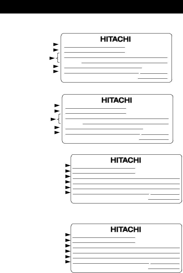
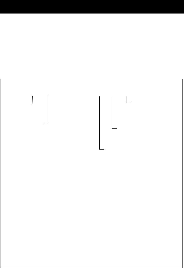
(3) Check on the specification nameplate whether the product is as ordered or not.
(a) |
Specification |
(b) |
|
nameplate |
|
|
(Located on the |
|
|
front cover for |
|
|
3-phase 400V |
(d) |
|
3.5kW and |
|
|
|
|
|
7kW) |
HITACHI AC Servo Drives |
|
|
|
(c) |
|
ADAX4 Series |
|
Instruction Manual |
|
3-phase 400V |
|
|
1.5, 3.5kW |
|
|
(Without cover) |
|
HITACHI |
|
|
|
Specification nameplate position |
|
|
(200V class and 400V 1.5kW) |
|
|
(e)
(e) Only ADAX4- MB
2 - 2
CHAPTER 2 INTRODUCTION
[200V class servo amplifiers]
Drive model |
|
|
|
|
|
|
|
|
|
Model : ADAX3-02NSE |
|
|
|
|
|||||
Applicable motor |
|
|
|
|
|
|
|
|
|
|
|
|
|
||||||
|
|
|
|
|
|
|
|
|
kW |
0.2 |
|
|
|
|
|
|
|||
|
|
|
|
|
|
|
|
|
|
||||||||||
maximum rated output |
Input |
: 1Ph |
220-230 |
V |
2.5 |
A 50Hz,60Hz |
|||||||||||||
Input rating |
|
|
|
|
|
|
|
|
|
||||||||||
|
|
|
|
|
|
|
|
Input : |
3Ph 200-230 |
V |
1.5 |
A |
50Hz ,60Hz |
||||||
|
|
|
|
|
|
|
|
|
|
||||||||||
Output rating |
|
|
|
|
|
|
|
|
Output : 3Ph 230 |
Vmax |
1.7 |
A |
|
|
|||||
|
|
|
|
|
|||||||||||||||
Production number |
|
|
|
|
|
|
|
|
MFG No. 212U N12345 20001 |
Date: 0209 |
|||||||||
|
|
|
|||||||||||||||||
|
|
|
|
|
|
|
|
|
|
|
Systems Co.,Ltd. |
MADE IN JAPAN NE17121 -39 |
|||||||
|
|
|
|
|
|
|
|
|
|
Hitachi Industrial Equipment |
|
|
|
|
|
||||
[200V class servo amplifiers with Modbus optional board] |
|
|
|
|
|||||||||||||||
Drive model |
|
|
|
|
Model : ADAX3-02NSEMB |
|
|
|
|
||||||||||
Applicable motor |
|
|
|
|
|
|
|
|
|
|
|
|
|
||||||
|
|
|
|
kW |
|
0.2 |
|
|
|
|
|
|
|||||||
|
|
|
|
|
|
|
|
|
|
||||||||||
maximum rated output |
|
Input |
: 1Ph |
220-230 |
V |
2.5 |
A |
50Hz,60Hz |
|||||||||||
Input rating |
|
|
|
|
|
|
|
|
|
||||||||||
|
|
|
Input : |
3Ph 200-230 |
V |
1.5 |
A |
50Hz ,60Hz |
|||||||||||
|
|
|
|
|
|
|
|
|
|
|
|||||||||
Output rating |
|
|
|
Output : 3Ph 230 |
Vmax |
1.7 |
A |
|
|
||||||||||
|
|
|
|
||||||||||||||||
Production number |
|
|
|
MFG No. 212U N12345 20001 |
Date: 0209 |
||||||||||||||
|
|
||||||||||||||||||
|
|
|
|
|
|
|
|
|
|
|
Hitachi Industrial Equipment MADE IN JAPAN NE17121 -39 |
||||||||
|
|
|
|
|
|
|
|
|
|
|
Systems Co.,Ltd. |
|
|
|
|
|
|
||
[400V class servo amplifiers] |
|
|
|
|
|
|
|
|
|
|
|||||||||
Drive model |
|
|
|
Model : ADAX3-35HPE |
|
|
|
|
|||||||||||
Applicable motor |
|
|
|
|
|
|
|
||||||||||||
maximum rated output |
|
|
|
kW |
|
3.5 |
200-240 V 0.3 A |
50Hz,60Hz |
|||||||||||
Control power circuit input |
|
|
Input(Control): 1Ph |
||||||||||||||||
|
|
||||||||||||||||||
Main power circuit Input |
|
|
Input(Main) : 3Ph |
380-480 V 13 A 50Hz,60Hz |
|||||||||||||||
|
|
||||||||||||||||||
Output rating |
|
|
Output |
: 3Ph 480 |
Vmax 12 A |
0 -420Hz |
|||||||||||||
|
|
||||||||||||||||||
Production number |
|
|
MFG No. |
24A N12345 20001 |
Date: 0209 |
||||||||||||||
|
|
||||||||||||||||||
|
|
|
|
|
|
|
|
|
|
|
Hitachi Industrial Equipment |
|
|
NE17609 -2 |
|||||
|
|
|
|
|
|
|
|
|
|
|
|
Systems Co.,Ltd. |
MADE IN JAPAN |
|
|||||
[400V class servo amplifiers with Modbus optional board]
Drive model |
|
Model : ADAX3-35HPEMB |
|
|
||
Applicable motor |
|
|
|
|||
maximum rated output |
|
kW |
3.5 |
200-240 V |
0.3 A 50Hz,60Hz |
|
Control power circuit input |
|
Input(Control): 1Ph |
||||
|
||||||
Main power circuit Input |
|
Input(Main) |
: 3Ph |
380-480 V |
13 |
A 50Hz,60Hz |
|
||||||
Output rating |
|
Output |
: 3Ph |
480 Vmax |
12 |
A 0 -420Hz |
|
||||||
Production number |
|
MFG No. 24A N12345 20001 |
Date: 0209 |
|
|
||||
|
|
Hitachi Industrial Equipment |
NE17609 -2 |
|
|
|
Systems Co.,Ltd. |
MADE IN JAPAN |
|
Contents of Specification Nameplate
2 - 3
CHAPTER 2 INTRODUCTION
(4)When the 200V class servo motor with the serial incremental encoder (17bit / revolution) is different from the specification of the standard product, connect the encoder and then perform initialize processing. For the procedure, refer to Chapter 5, “Clearing the Trip Log and Performing Factory-setting”.
(5)In case that you use the motor with the serial absolute encoder (17bit / revolution), Absolute Battery Error (E90) occurs after connecting the backup battery and turning on the power supply. Clear the trip and then clear the encoder data. For the procedure, refer to Chapter 5, “Functions for Absolute Position Encoder”, (2) Clearing the absolute position.
|
|
|
|
|
Explanation of Drive model |
|
|
|
|
|
|
|
|
|||||||||||||
|
|
|
|
|
|
|
|
|
|
|
|
|
||||||||||||||
|
|
|
|
|
|
|
|
|
|
|
|
|
|
|
|
|
|
|
|
|
|
|
|
|
|
|
|
AD |
AX4 |
– |
08 |
|
N |
|
|
S |
E |
MB |
|
|
|
|
|
|
|||||||||
|
|
|
|
|
|
|
|
|
|
|
|
|
|
|
|
|
|
|
|
|
|
|
|
|
|
|
Series name |
|
|
|
|
|
|
|
|
|
|
|
|
|
|
|
|
|
|
Option |
|
|
|
|
|||
|
|
|
|
|
|
|
|
|
|
|
|
|
|
|
|
|
|
|
|
|
|
|
||||
|
|
|
|
|
|
|
|
|
|
|
|
|
|
|
|
|
|
|
None : Standard |
|||||||
AD : AD series |
|
|
|
|
|
|
|
|
|
|
|
|
|
|
|
|
|
|
|
|||||||
|
|
|
|
|
|
|
|
|
|
|
|
|
|
|
|
|
|
|
MB |
: Modbus |
||||||
|
|
|
|
|
|
|
|
|
|
|
|
|
|
|
|
|
|
|
|
|
||||||
Drive name |
|
|
|
|
|
|
|
|
|
|
|
|
|
|
|
I/O polarity |
|
|
|
|
|
|||||
AX4 : Programmable |
|
|
|
|
|
|
|
|
|
|
|
|
|
|
Output…Sink |
|||||||||||
|
function build-in |
|
|
|
|
|
|
|
|
|
|
|
|
|
None: Input…Sink/Source |
|||||||||||
|
|
|
|
|
|
|
|
|
|
|
|
|
|
|
|
Pulse input… insulation |
||||||||||
|
|
|
|
|
|
|
|
|
|
|
|
|
|
|
|
|
E: |
Input…Sink/Source |
Output…Source |
|||||||
|
|
|
|
|
|
|
|
|
|
|
|
|
|
|
|
|
|
|
Pulse input… no insulation |
|||||||
|
|
|
|
|
|
|
|
|
|
|
|
|
|
|
Encoder type |
|
|
|
|
|
|
|||||
|
|
|
|
|
|
|
|
|
|
|
|
|
|
|
|
S: 17bit / revolutionSerial encoder |
||||||||||
|
|
|
|
|
|
|
|
|
|
|
|
|
|
|
|
|
(Incremental, Absolute) |
|||||||||
|
|
|
|
|
|
|
|
|
|
|
|
|
|
|
|
P: Wire-saving incremental encoder |
||||||||||
|
|
|
|
|
|
|
|
|
|
|
|
|
Input power supply |
|
|
|
|
|
|
|||||||
|
|
|
|
|
|
|
|
|
|
|
|
|
|
|
|
|
|
|
||||||||
|
|
|
|
|
|
|
|
|
|
|
|
|
|
M: Single phase 100V class |
||||||||||||
|
|
|
|
|
|
|
|
|
|
|
|
|
|
L: Three phase 200V class |
|
|
|
|
||||||||
|
|
|
|
|
|
|
|
|
|
|
|
|
|
N: Single / Three phase 200V class |
||||||||||||
|
|
|
|
|
|
|
|
|
|
|
|
|
|
H: Three phase 400V class |
||||||||||||
|
|
|
|
|
|
|
|
|
|
Output rating |
|
|
|
|
|
|
|
|
|
|
|
|||||
|
|
|
|
|
|
|
|
|
|
|
|
|
|
|
|
|
|
|
|
|
||||||
|
|
|
|
|
|
|
|
|
|
|
|
|
|
|
|
|
|
|
|
|
|
|
||||
|
Symbol |
R5 |
01 |
|
02 |
|
04 |
|
08 |
|
10 |
|
15 |
|
20 |
|
35 |
50 |
|
70 |
|
|
||||
|
Rating(kW) |
0.05 |
|
0.1 |
|
0.2 |
|
0.4 |
|
0.8 |
|
1.0 |
|
1.5 |
|
2.0 |
|
3.5 |
5.0 |
|
7 |
|
|
|||
|
Voltage |
M |
M |
|
M |
M |
- |
|
- |
|
- |
|
- |
|
- |
- |
|
- |
|
|
||||||
|
|
L |
L |
|
L |
L |
L |
|
L |
|
L |
|
L |
L |
L |
|
- |
|
|
|||||||
|
|
- |
|
N |
|
N |
N |
N |
|
- |
|
- |
|
- |
|
- |
- |
|
- |
|
|
|||||
|
|
- |
|
- |
|
|
|
|
|
|
|
- |
|
- |
|
H |
|
- |
|
H |
- |
|
H |
|
||
(Note) Drive is becomes an article of order by combination of input power supply, Encoder type and
I/O polarity. Refer to chapter 8 for Standard models.
2 - 4
CHAPTER 2 INSTRUCTION
2.1.2Instruction manual
This instruction manual explains the detail of the Hitachi AD series servo.
Please read this manual thoroughly to operate the product correctly before operating it. Keep the manual in custody with care.
When using option products related to this servo drive, read the instruction manuals for the related products thoroughly.
2.2Inquiry about the Product and Warranty
2.2.1Notes for making an inquiry
If you have to make an inquiry about product damage, doubt, failure, etc., inform the dealer of the following items.
(1)Servo drive type and form (model No.)
(2)Production number (MFG. No.)
(3)Date of purchase
(4)Contents of your inquiry
-Damage position, status, etc.
-Doubtful item, contents, etc.
2.2.2Product warranty
The product warranty period shall be one year after purchase.
In the following cases, however, the product is out of the warranty range and shall be repaired with charge even within the warranty period.
(1)The failure is due to an operation error or improper repair or modification.
(2)The failure is due to any other reason that is not related to your purchased product.
(3)The product was operated over the specification value range.
(4)The failure is due to a natural calamity, disaster, or secondary disaster.
The warranty herein referred to means the warranty of the delivered product proper. Any damage induced by a failure of the delivered product shall be excluded.
2.2.3Charged repair
After the lapse of the warranty period (one year), any investigation and repair shall be performed with charge. In the warranty period, repair or investigation that is out of the above warranty range shall be undertaken with charge.
For asking for a charged repair, contact with the dealer.
2 - 5

CHAPTER 2 INSTRUCTION
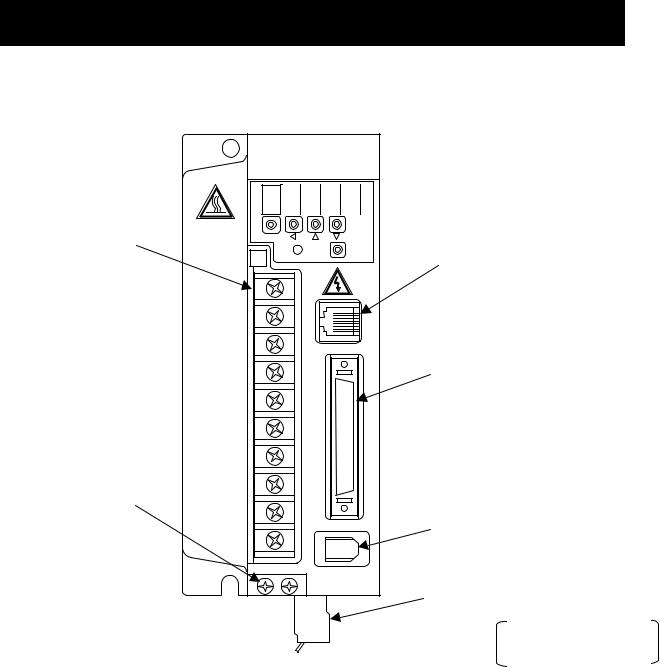
2.3Appearance and Names of Parts
(The following drawings describe 200V class servo without optional board.)
Battery housing cover
A cover for the battery holder.
Battery holder
Houses the backup battery when
the absolute encoder is used. Battery connector
Used to connect the backup battery for the absolute encoder.
Panel display unit
Used to indicate the servo drive condition or parameter setting by using a 5-digit 7-segment LED.
Charge lamp |
|
|
Lights up when the main circuit |
|
|
power supply is turned on. While |
|
|
the electric charge remains on the |
|
|
main circuit capacitor after the |
|
|
power supply is turned off, this |
|
|
lamp continues to light. Do not |
|
|
touch the servo drive during |
Digital operator |
|
lighting. |
||
|
Used to set parameters. |
|
Main circuit terminal block (TM1) |
Connector for connecting a PC |
|
Connection terminals with the main circuit |
||
(PC) |
||
power supply, external regenerative |
||
A connector for communication with |
||
resistor, and motor power cable. |
||
a PC. |
||
This terminal block is covered with a cover. |
||
|
||
Exhaust |
Input/output signal connector |
|
air |
(I/O) |
|
|
A connector for command input |
|
|
signals and sequencer input signals. |
|
|
Specification nameplate |
|
|
Used to indicate the servo |
|
|
drive type and form and |
|
|
ratings. |
|
|
Encoder connector (ENC) |
|
|
Used to connect the encoder of |
|
|
the servo motor. |
|
|
Control power supply connector |
|
|
(TM2) |
|
|
A connector for connecting the |
|
|
control power supply. |
|
|
B1-B2 short bar |
|
Ground terminal |
Be sure to connect this |
|
Used for protection against an |
short bar when using the |
|
electric shock. |
internal braking resistor. |
Intake air
2 - 6

CHAPTER 2 INSTRUCTION
2.4 Combination of servo amplifiers and servo motors
The applicable combination of servo amplifiers and servo motors is shown in the following table.
Phase / |
|
|
|
|
|
|
Servo amplifier |
|
Applicable servo motor |
|
Voltage |
|
|
Rated |
|
Output |
|
|
|||
|
|
|
|
|
|
|
||||
for main |
|
|
|
|
Model code |
|
With |
With |
||
|
|
speed |
|
(kW) |
|
|
||||
power |
|
|
|
|
|
|
Incremental |
Absolute |
||
|
|
|
|
|
|
|
|
|||
circuit |
|
|
|
|
|
|
|
|
encoder |
encoder |
|
|
|
|
|
|
|
|
|
|
|
|
|
|
|
|
0.1 |
|
ADAX4-01NSE(MB) |
— |
ADMA-01SA |
ADMA-01SF |
Single-phase |
|
|
|
|
|
|
|
|
|
|
|
|
|
|
0.2 |
|
ADAX4-02NSE(MB) |
— |
ADMA-02SA |
ADMA-02SF |
|
220~230V |
|
|
3000 |
|
|
|||||
|
|
|
|
|
|
|
|
|||
/3-phase |
|
|
(min-1) |
|
0.4 |
|
ADAX4-04NSE(MB) |
— |
ADMA-04SA |
ADMA-04SF |
200~230V |
|
|
|
|
|
|
|
|
|
|
|
|
|
|
0.7 |
|
ADAX4-08NSE(MB) |
— |
ADMA-08SA |
ADMA-08SF |
|
|
|
|
|
|
|
|||||
|
|
|
|
|
5 |
|
||||
|
|
|
|
|
|
|
|
|
|
|
|
|
|
|
|
|
|
|
|
|
|
|
|
|
|
|
0.5 |
|
|
— |
ADMG-05HP |
|
|
|
|
|
|
|
|
Note 2) |
|
|
|
|
|
|
|
|
1.0 |
|
— |
ADMG-10HP |
|
|
|
|
|
|
|
|
ADAX4-15HPE(MB) |
|
|||
|
|
|
|
|
1.5 |
|
|
— |
ADMG-15HP |
|
|
|
|
|
|
|
|
|
|
|
|
3-phase |
|
2000 |
|
2.0 |
|
Note 2) |
— |
ADMG-20HP |
|
|
380~480V |
|
|
(min-1) |
|
3.5 |
|
ADAX4-35HPE(MB) |
— |
ADMG-35HP |
|
|
|
|
|
|
|
|
|
|||
|
|
|
|
|
|
|
|
|
|
|
|
|
|
|
|
4.5 |
|
|
— |
ADMG-45HP |
|
|
|
|
|
|
|
|
Note 2) |
|
|
|
|
|
|
|
|
5.5 |
|
— |
ADMG-55HP |
|
|
|
|
|
|
|
|
ADAX4-70HPE(MB) |
|
|||
|
|
|
|
|
7.0 |
|
|
— |
ADMG-70HP |
|
|
|
|
|
|
|
|
|
|
|
|
Note 1) ADAX4 describes the standard high performance type, and ADAX3 describe the programmable function built-in type.
Note 2) Single-phase 200 ~ 240V is needed for the control power circuit. Do not supply 3-phase
2 - 7

MEMO
2 - 8

CHAPTER 3 INSTALLATION AND WIRING
This chapter explains the procedure for installing this product, main circuit wiring, and input/output signal wiring. Typical connection examples are shown.
3.1 Installation ................................................... |
3 |
− 2 |
|
3.1.1 |
Precautions on installation..................... |
3 |
− 3 |
3.2 Wiring .......................................................... |
3 |
− 5 |
|
3.2.1 |
Terminals and connectors...................... |
3 |
− 6 |
3.2.2 |
Main circuit wiring.................................. |
3 |
− 9 |
3.2.3 Wiring for the control power |
|
|
|
|
connector (TM2) (200V class) .............. |
3 |
− 21 |
3.2.4 |
Connecting the backup |
|
|
|
battery for absolute encoder.................. |
3 |
− 22 |
3.2.5 |
Input/output signal wiring....................... |
3 |
− 23 |
3.2.6 Wiring for encoder signals ..................... |
3 |
− 39 |
|
3 − 1

CHAPTER 3 INSTALLATION AND WIRING
3.1 Installation
 CAUTION
•Be sure to install the unit on flame resistant material such as metal. Otherwise, there is a danger of fire.
•Be sure not to place anything inflammable in the vicinity. Otherwise, there is a danger of fire.
•Do not carry unit by top cover, always carry by supporting base of unit. There is a risk of falling and injury.
•Be sure not to let the foreign matter enter such as cut wire refuse, spatter from welding, iron refuse, wire, dust, etc.
Otherwise, there is a danger of fire.
•Be sure to install it in a place which can bear the weight according to the specifications in the text.
Otherwise, it may fall and there is a danger of injury.
•Be sure to install the unit on a perpendicular wall which is not subject to vibration. Otherwise, it may fall and there is a danger of injury.
•Be sure not to install and operate AC servo drive which is damaged or parts of which are missing.
Otherwise, there is a danger of injury.
•Be sure to install it in a room which is not exposed to direct sunlight and is well ventilated. Avoid environments which tend to be high in temperature, high in humidity or to have dew condensation, as well as places with dust, corrosive gas, explosive gas, inflammable gas, grinding-fluid mist, salt damage, etc.
Otherwise, there is a danger of fire.
A failure will be caused.
•Be sure to connect between servo drive logic ground (L) and controller ground when pulse train input is used by servo drive with source type logic.
Otherwise, A equipment failure will be caused.
3 − 2
CHAPTER 3 INSTALLATION AND WIRING
3.1.1 Precautions on installation
1) Precaution at transportation
The servo drive employs plastic parts. Handle it so that these plastic parts may not be damaged. In particular, do not carry the servo drive in such a way that force is applied to only the front surface cover and the terminal block cover. Falling may be caused.
If any part is damaged or missing, do not install and operate the servo drive.
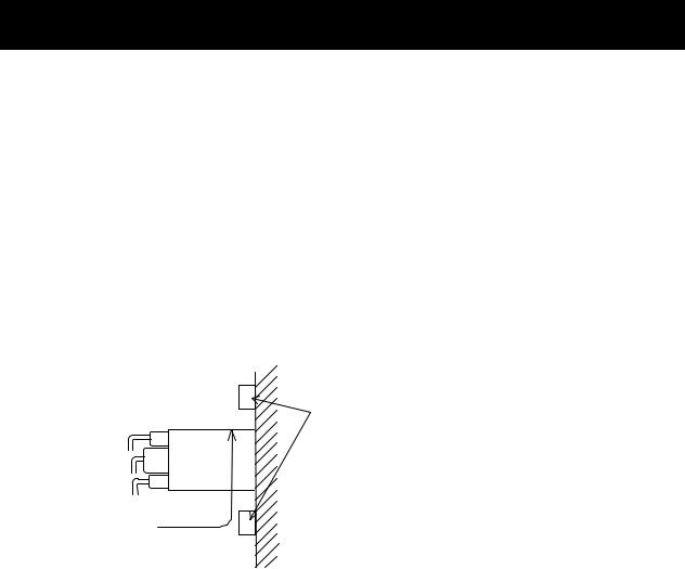
2) Install the servo drive on an incombustible (metal) surface.
The servo drive goes to a high temperature. Install the servo drive on an incombustible vertical metal wall surface so as to avoid a fire.
Ensure an enough space around the installation place. In particular, if there is any heat generating device (braking resistor, reactor, etc.), keep the servo drive away from such a material.
Air flow
Servo drive
Ensure an enough space so that the upper/lower wiring ducts may not prevent the cooling air from flowing.
Wall
3) Precaution about the ambient temperature
The ambient temperature in the installation place should not exceed the allowable operating temperature range (0 to 55°C) described in the standard specification.
Measure the ambient temperature at an about 50 mm position away from the lower center of the servo drive body, and make sure that it is within the allowable operating temperature range. Operating the servo drive over the allowable operating temperature range may lead to its shorter life (especially, the life of the capacitor) or damage.
4)Do not install the servo drive in a high-temperature and high-humidity place that may easily cause condensation.
Operate the servo drive within the allowable operating humidity range (20 to 90%RH) described in the standard specification. In particular, operate it in a place free from condensation.
If water-drops are attached inside the servo drive by condensation, the section between electronic parts is shorted, resulting in a failure.
Avoid installing the servo drive in a place that is exposed to direct sunlight.
5)Precaution about the installing environment
Do not install the servo drive in a place where there is dust, corrosive gas, explosive gas, combustible gas, grinding lubricant mist, or injury from salt. Admitting foreign substances or dust inside the servo drive will result in a failure.
Therefore, if the servo drive must be operated in very dusty place, for example, house it in a sealed type box.
3 − 3
CHAPTER 3 INSTALLATION AND WIRING
6)Precaution about the installing method and direction
Install the servo drive on a mounting surface that can withstand its weight, firmly and vertically without any screw or bolt looseness.
If the servo drive is not installed vertically on the wall surface, it may lower the cooling capacity with a result of trip or damage.
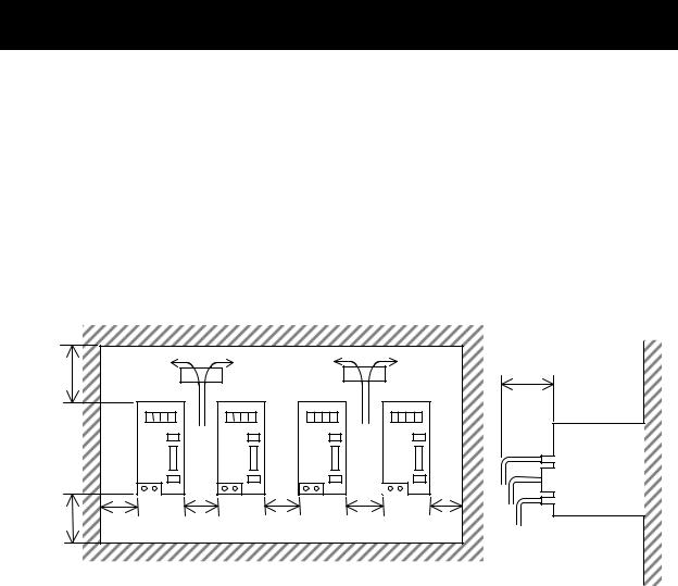
7)Precaution for housing servo drives in a box
When multiple servo drives are housed in a box and ventilation fans are equipped in the box, provide the fans in the following way so as to make the ambient temperature of each servo drive uniform.
100 mm or more
100 mm
or more 40 mm
or more
Fan |
10 mm |
10 mm |
or more |
or more |
Fan |
10 mm |
40 mm |
or more |
or more |
Wiring space of 75 mm or more
Servo drive
In the case of boxes arranged in a row, install them at 40 mm or more from the wall surfaces with a space of 10 mm or more between servo drives and a clearance of 100 mm or more from the top or bottom.
3 − 4
CHAPTER 3 INSTALLATION AND WIRING
3.2Wiring
WARNING
• Be sure to ground the unit.
Otherwise, there is a danger of electric shock and/or fire.
•Wiring work shall be carried out by electrical experts. Otherwise, there is a danger of electric shock and/or fire.
•Implement wiring after checking that the power supply is off. It might incur electric shock and/or fire.
•After installing the main body, carry out wiring.
Otherwise, there is a danger of electric shock and/or injury.
CAUTION
• Make sure that the input voltage is:
Three phase 200 to 230V 50/60Hz (for models with suffix L) Single phase 100 to 115V 50/60Hz (for models with suffix M)
Single phase 220 to 230V / Three phase 200 to 230V 50/60Hz (for models with suffix N) Three phase 380 to 480V 50/60Hz (for models with suffix H)
Control power supply 200 to 240V 50/60Hz (for models with suffix H) Otherwise, there is a danger of fire.
•Be sure not to input a single phase for models with suffix H. Otherwise, there is a danger of fire.
•Be sure not to connect AC power supply to the output terminals(U, V, W). Otherwise, there is a danger of injury and/or fire.
•Be sure not to connect the resistor to DC terminals (+1,+ and –) directly. Otherwise, there is a danger of fire.
•As for motor leads, fuses and electromagnetic contactors, be sure to use the equivalent ones with the specified capacity (rated).
Otherwise, there is a danger of fire.
•Fasten the screws with the specified fastening torque. Check so that there is no loosening of screws.
Otherwise, there is a danger of fire.
•Connection to field wiring terminals must be reliably fixed having two independent means of support. Using terminal with cable support, cable gland or cable clamp etc.
Otherwise, there is a danger of fire.
•Be sure to connect between the servo drive logic common and master controller logic common when using pulse count input on source type logic.
Otherwise, there is a danger of equipment failure.
3 − 5
CHAPTER 3 INSTALLATION AND WIRING
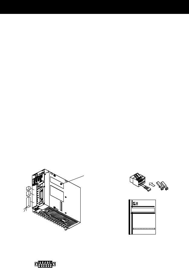
3.2.1Terminals and connectors
(1) 200V class [less or equal 1.5kW(ADAX4LS(MB) )] [less or equal 750W(ADAX4NS(MB) )]
AC SERVO |
HITACHI |
AD |
AD*-04NSE |
series |
|
Main circuit |
|
terminals (TM1) |
|
FUNC |
|
CHARGE |
SET |
Grounding |
|
terminal |
|
PC connecting connector (PC)
Input/output signal connector (I/O)
Encoder (sensor) connector (ENC)
Control power connector (TM2)
This figure is without optional board
3 − 6
Loading...