


Hikvision DS-2CE16H0T-IT3F-12mm, DS-2CE16H0T-IT3F-2-8mm, DS-2CE16H0T-IT3F-3-6mm, DS-2CE16H0T-IT3F-6mm, DS-2CE16H0T-IT3F-8mm User Manual
• DS-2CE16H0T-ITF
• DS-2CE16H0T-IT3F
• DS-2CE16H0T-IT5F
• DS-2CE56H0T-VPITF
TurboHD
H0T Series
Bullet and Dome Camera
User Manual
Thank you for purchasing our product. If there are any questions or requests, do not hesitate to contact the dealer.
This manual applies to the models below:
Type |
Model |
|
Type I Camera |
DS-2CE16H0T-ITF |
|
Type II Camera |
DS-2CE16H0T-IT3F |
|
DS-2CE16H0T-IT5F |
||
|
||
Type III Camera |
DS-2CE56H0T-VPITF |
Hikvision USA Inc., 18639 Railroad St., City of Industry, CA 91748, USA • Hikvision Canada, 4848 rue Levy, Saint Laurent, Quebec, Canada, H4R 2P1
Telephone: +1-909-895-0400 • Toll Free in USA: +1- 866-200-6690 • E-Mail: sales.usa@hikvision.com • www.hikvision.com
COPYRIGHT ©2017-2018 Hangzhou Hikvision Digital Technology Co., Ltd. ALL RIGHTS RESERVED.
Any and all information, including, among others, wordings, pictures, graphs are the properties of Hangzhou Hikvision Digital Technology Co., Ltd. or its subsidiaries (hereinafter referred to be “Hikvision”). This user manual (hereinafter referred to be “the Manual”) cannot be reproduced, changed, translated, or distributed, partially or wholly, by any means, without the prior written permission of Hikvision. Unless otherwise stipulated, Hikvision does not make any warranties, guarantees or representations, express or implied, regarding to the Manual.
This manual may contain technical or printing errors, and the content is subject to change without notice. Updates will be added to new versions of this manual. We will readily improve or update the products or procedures described in the manual.
UM DS-2CEx6H0T-xxITxF 042618NA |
1 |
1 Preface
1.1Regulatory Information
1.1.1FCC Information
Please take attention that changes or modification not expressly approved by the party responsible for compliance could void the user’s authority to operate the equipment.
FCC Compliance: This equipment has been tested and found to comply with the limits for a Class A digital device, pursuant to part 15 of the FCC Rules. These limits are designed to provide reasonable protection against harmful interference when the equipment is operated in a commercial environment. This equipment generates, uses, and can radiate radio frequency energy and, if not installed and used in accordance with the instruction manual, may cause harmful interference to radio communications. Operation of this equipment in a residential area is likely to cause harmful interference, in which case the user will be required to correct the interference at his own expense.
1.1.2FCC Conditions
This device complies with part 15 of the FCC Rules. Operation is subject to the following two conditions:
1.This device may not cause harmful interference.
2.This device must accept any interference received, including interference that may cause undesired operation.
1.1.3EU Conformity Statement
This product and, if applicable, the supplied accessories too are markedwith “CE” and comply therefore with the applicable harmonized European standards listed under the Low Voltage Directive 2014/35/EU, the EMC Directive
2012/19/EU (WEEE Directive): Products marked with this symbol cannot be disposed of as unsorted municipal waste in the European Union. For proper recycling, return this product to your local supplier upon the purchase of equivalent new equipment, or dispose of it at designated collection points. For more information see: www.recyclethis.info.
2006/66/EC (Battery Directive): This product contains a battery that cannot be disposed of as unsorted municipal waste in the European Union. See the product documentation for specific battery information. The battery is marked with this symbol, which may include lettering to indicate cadmium (Cd), lead (Pb), or mercury (Hg). For proper recycling, return the battery to your supplier or to a designated collection point. For more information see: www.recyclethis.info.
UM DS-2CEx6H0T-xxITxF 042618NA |
2 |
1.1.4Industry Canada ICES-003 Compliance
This device meets the CAN ICES-3 (A)/NMB-3(A) standards requirements.
1.1.5Safety Instruction
These instructions are intended to ensure that the user can use the product correctly to avoid danger or property loss.
The precaution measure is divided into “Warnings” and “Cautions.”
Warnings: Serious injury or death may occur if any of the warnings are neglected.
Cautions: Injury or equipment damage may occur if any of the cautions are neglected.
|
|
Warnings Follow these |
Cautions Follow these |
safeguards to prevent |
precautions to prevent |
serious injury or death. |
potential injury or |
|
material damage. |
1.1.6Warnings
•In the use of the device, you must be in strict compliance with the electrical safety regulations of the nation and region.
•Input voltage should meet both the SELV (Safety Extra Low Voltage) and the Limited Power Source with 12 VDC according to the IEC60950-1 standard. Refer to technical specifications for detailed information.
•The camera is powered by the external DC power supply (12 VDC, 1 A) that complies with the LPS, and the output current of this external DC power supply must be no more than 6 A.
•Do not connect multiple devices to one power adapter to avoid over-heating or a fire hazard caused by overload.
•Make sure that the plug is firmly connected to the power socket.
•Make sure that the device is firmly fixed if wall mounting or ceiling mounting is adopted.
•If smoke, odor, or noise rise from the device, turn off the power at once and unplug the power cord, and then contact the service center.
•Never attempt to disassemble the camera by unprofessional personal.
1.1.7Cautions
•Do not drop the camera or subject it to physical shock.
•Do not touch senor modules with fingers.
UM DS-2CEx6H0T-xxITxF 042618NA |
3 |
•Do not place the camera in extremely hot, cold (the operating temperature shall be -40° to 60° C), dusty or damp locations, and do not expose it to high electromagnetic radiation.
•If cleaning is necessary, use a clean cloth with a bit of ethanol, and wipe it gently.
•Do not aim the camera at the sun or extra bright places.
•The sensor may be burned out by a laser beam, so when any laser equipment is in using, make sure that the sensor surface will not be exposed to the laser beam.
•Do not expose the device to high electromagnetic radiation or extremely hot, cold, dusty, or damp environments.
•To avoid heat accumulation, good ventilation is required for the operating environment.
•Keep the camera away from liquid while in use for non-waterproof devices.
•While in delivery, the camera shall be packed in its original packing, or packing of the same material.
1.1.8Mark Description
Table 0-1 Mark Description
Mark |
Description |
|
DC Voltage |
2 Introduction
2.1Product Features
The camera is applicble for both indoor and outdoor conditions, and the application scenarios include road, warehouse, underground parking lot, bar, etc.
The main features are as follows:
•High performance CMOS sensor
•IR cut filter with auto switch
•OSD menu with configurable parameters
•Auto white balance
•internal synchronization
•SMART IR mode
•3-axis adjustment
2.2Overview
2.2.1Overview of Type I Camera
Figure 1 Overview of Type I Camera
UM DS-2CEx6H0T-xxITxF 042618NA |
4 |

Note:
To switch the video output, press and hold the switch button until the image turns black, then release. Cycle through available types to return to the default HD-TVI output. Four kinds of video outputs are available: TVI, AHD, CVI, and CVBS.
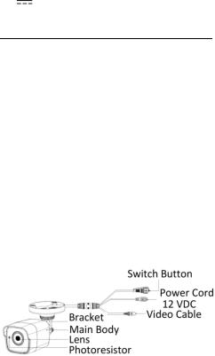
2.2.2Overview of Type II Camera
Figure 2 Overview of Type II Camera
Note:
To switch the video output, press and hold the switch button until the image turns black, then release. Cycle through available types to return to the default HD-TVI output. Four kinds of video outputs are available: TVI, AHD, CVI, and CVBS.
2.2.3Overview of Type III Camera
Figure 3 Overview of Type III Camera
Note:
To switch the video output, press and hold the switch button until the image turns black, then release. Cycle through available types to return to the default HD-TVI output. Four kinds of video outputs are available: TVI, AHD, CVI, and CVBS.
3 Installation
Before you start:
•Make sure that the device in the package is in good condition and all the assembly parts areincluded.
•Make sure that all the related equipment is powered off during the installation.
•Check the specification of the products for the installation environment.
•Check whether the power supply is matched with your power output to avoid the damage.
UM DS-2CEx6H0T-xxITxF 042618NA |
5 |
•Make sure the wall is strong enough to withstand three times the weight of the camera and the mount.
•If the wall is cement, insert expansion bolts before installing the camera. If the wall is wooden, use self-tapping screws to secure the camera.
•If the product does not function properly, contact your dealer or the nearest service center. Do NOT disassemble the camera for repair or maintenance by yourself.
3.1Installation of Type I Camera
3.1.1Ceiling/Wall Mounting without Junction Box
Steps:
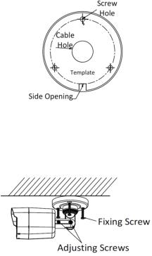
1.Paste the drill template (supplied) where you want to install the camera.
2.Drill the screw holes and the cable hole (optional) in the ceiling/wall according to the drill template.
Figure 4 Drill Template
Note:
Drill the cable hole when using the ceiling outlet to route the cable.
3.Attach the bracket to the ceiling/wall and secure the camera with supplied screws.
Figure 5 Fix the Camera to the Ceiling
Note:
•The supplied screw package contains self-tapping screws and expansion bolts.
•For a cement wall/ceiling, expansion bolts are required to fix the camera. For a wooden wall/ceiling, self-tapping screws are required.
4.Route the cables through the cable hole or the side opening.
UM DS-2CEx6H0T-xxITxF 042618NA |
6 |
 Loading...