


Henny Penny
Pressure Fryer
Model PFE-590
Model PFE-592
OPERATOR’S MANUAL

LIMITED WARRANTY FOR HENNY PENNY EQUIPMENT
Subject to the following conditions, Henny Penny Corporation makes the following limited warranties to the original purchaser only for Henny Penny appliances and replacement parts:
NEW EQUIPMENT: Any part of a new appliance, except baskets, lamps, and fuses, which proves to be defective in material or workmanship within two (2) years from date of original installation, will be repaired or replaced without charge F.O.B. factory, Eaton, Ohio, or F.O.B. authorized distributor. Baskets will be repaired or replaced for ninety (90) days from date of original installation. Lamps and fuses are not covered under this Limited Warranty. To validate this warranty, the registration card for the appliance must be mailed to Henny Penny within ten (10) days after installation.
FILTER SYSTEM: Failure of any parts within a fryer filter system caused by the use of the non-OEM filters or other unapproved filters is not covered under this Limited Warranty.
REPLACEMENT PARTS: Any appliance replacement part, except lamps and fuses, which proves to be defective in material or workmanship within ninety (90) days from date of original installation will be repaired or replaced without charge F.O.B. factory, Eaton, Ohio, or F.O.B. authorized distributor.
The warranty for new equipment covers the repair or replacement of the defective part and includes labor charges and maximum mileage charges of 200 miles round trip for a period of one (1) year from the date of original installation.
The warranty for replacement parts covers only the repair or replacement of the defective part and does not include any labor charges for the removal and installation of any parts, travel, or other expenses incidental to the repair or replacement of a part.
EXTENDED FRYPOT WARRANTY: Henny Penny will replace any frypot that fails due to manufacturing or workmanship issues for a period of up to seven (7) years from date of manufacture. This warranty shall not cover any frypot that fails due to any misuse or abuse, such as heating of the frypot without shortening.
0 TO 3 YEARS: During this time, any frypot that fails due to manufacturing or workmanship issues will be replaced at no charge for parts, labor, or freight. Henny Penny will either install a new frypot at no cost or provide a new or reconditioned replacement fryer at no cost.
3 TO 7 YEARS: During this time, any frypot that fails due to manufacturing or workmanship issues will be replaced at no charge for the frypot only. Any freight charges and labor costs to install the new frypot as well as the cost of any other parts replaced, such as insulation, thermal sensors, high limits, fittings, and hardware, will be the responsibility of the owner.
Any claim must be presented to either Henny Penny or the distributor from whom the appliance was purchased. No allowance will be granted for repairs made by anyone else without Henny Penny’s written consent. If damage occurs during shipping, notify the sender at once so that a claim may be filed.
THEABOVE LIMITED WARRANTYSETS FORTHTHE SOLE REMEDYAGAINST HENNYPENNYFORANYBREACH OF WARRANTY OR OTHER TERM. BUYERAGREES THAT NO OTHER REMEDY(INCLUDING CLAIMS FORANYINCIDENTALOR CONSEQUENTIALDAMAGES) SHALLBEAVAILABLE.
The above limited warranty does not apply (a) to damage resulting from accident, alteration, misuse, or abuse; (b) if the equipment’s serial number is removed or defaced; or (c) for lamps and fuses. THE ABOVE LIMITED WARRANTY IS EXPRESSLYIN LIEU OFALL OTHER WARRANTIES, EXPRESS OR IMPLIED, INCLUDING MERCHANTABILITYAND FITNESS,ANDALLOTHER WARRANTIESARE EXCLUDED. HENNYPENNYNEITHERASSUMES NORAUTHORIZESANY PERSON TOASSUME FOR ITANYOTHER OBLIGATION OR LIABILITY.
Revised 01/01/07
FM05-032-G
Revised 8-6-10
HENNY PENNY
8 HEAD ELECTRIC PRESSURE FRYER
SPECIFICATIONS |
|
Height |
61" (155 cm) |
Width |
24" (61 cm) |
Depth |
41¾" ( 107 cm) |
Floor Space |
Approximately 7 sq. ft. (.65 sq. m.) |
Pot Capacity |
8 head of chicken - 22 lbs. (9.9 kg) |
|
100 lbs. shortening (45 Kg.) |
Electrical |
208 VAC, 3 Phase, 50/60 Hz, 17 KW, 47.2 Amps |
|
240 VAC, 3 Phase, 50/60 Hz, 17 KW, 40.9 Amps |
|
200 VAC, 3 Phase, (Delta), 50/60 Hz, 17 KW, 49.1 Amps |
|
240 VAC, 3 Phase, (Delta), 50 Hz, 17 KW, 40.9 Amps |
|
380 VAC, 3 Phase, 50 Hz, 17 KW, 25.8 Amps |
|
415 VAC, 3 Phase, 50 Hz, 17 KW, 23.7 Amps |
|
400 VAC, 3 Phase, 50 Hz, 17 KW, 24.6 Amps |
Heating |
Two 8,500 watt electric immersion elements |
ShippingWeight |
Approximately 758 lbs. (344 kg.) |
A data plate, located on the back shroud behind the lid, gives the information of the type of fryer, serial number, warranty date, and other information pertaining to fryer. Also, the serial number is stamped on the outside of the frypot. See figure below.
|
|
TABLE OF CONTENTS |
|
Section |
|
|
Page |
Section 1. |
INTRODUCTION .................................................................................................... |
1-1 |
|
|
1-1 |
Pressure Fryer ............................................................................................... |
1-1 |
|
1-2 |
Proper Care ................................................................................................... |
1-1 |
|
1-3 |
Assistance ..................................................................................................... |
1-1 |
|
1-4 |
Safety ............................................................................................................ |
1-2 |
Section 2. |
INSTALLATION ...................................................................................................... |
2-1 |
|
|
2-1 |
Introduction.................................................................................................... |
2-1 |
|
2-2 |
Unpacking ..................................................................................................... |
2-1 |
|
2-3 |
Selecting the Fryer Location ......................................................................... |
2-5 |
|
2-4 |
Leveling the Fryer ......................................................................................... |
2-5 |
|
2-5 |
Ventilation of Fryer ........................................................................................ |
2-6 |
|
2-6 |
Electrical Requirements ................................................................................ |
2-6 |
|
2-7 |
International Electrical Requirements ........................................................... |
2-7 |
Section 3. |
OPERATION ............................................................................................................ |
3-1 |
|
|
3-1 |
Operating Components .................................................................................. |
3-1 |
|
3-2 |
Lid Operation................................................................................................. |
3-3 |
|
3-3 |
Melt Cycle Operation .................................................................................... |
3-4 |
|
3-4 |
Switches and Indicators ................................................................................ |
3-5 |
|
3-5 |
Filling orAdding Shortening ........................................................................... |
3-8 |
|
3-6 |
Basic Operation ............................................................................................. |
3-9 |
|
3-7 |
Care of Shortening ........................................................................................ |
3-11 |
|
3-8 |
Filtering Instructions ...................................................................................... |
3-11 |
|
3-9 |
Changing the Filter Envelope......................................................................... |
3-13 |
|
3-10 |
Cleaning the Frypot ....................................................................................... |
3-14 |
|
3-11 |
Filter Pump Motor Protector-Manual Reset ................................................. |
3-15 |
|
3-12 |
Regular Maintenance Schedule ..................................................................... |
3-15 |
|
3-13 |
Preventive Maintenance ................................................................................ |
3-16 |
|
3-14 |
Programming ................................................................................................. |
3-19 |
|
3-15 |
Special Program Mode .................................................................................. |
3-21 |
Section 4. |
TROUBLESHOOTING ............................................................................................. |
4-1 |
|
|
4-1 |
Troubleshooting Guide .................................................................................... |
4-1 |
|
4-2 |
Error Codes .................................................................................................... |
4-2 |
GLOSSARY |
....................................................................................................................... |
G-1 |
|
1203 |
i |

Model PFE590/592
|
SECTION 1. INTRODUCTION |
|
|
1-1. PRESSURE FRYER |
The Henny Penny pressure fryer is a basic unit of food pro- |
|
cessing equipment which is used only in institutional and commercial |
|
food service operations. |
P-H-T |
A combination of pressure, heat, and time is automatically |
|
controlled to produce the optimum in a tasty, appealing |
|
product. |
Pressure |
Pressure is basic to this method of food preparation. The pres- |
|
sure is developed from the natural moisture of the food. The |
|
patented lid traps this moisture and uses it as steam. Because |
|
the steam builds rapidly, a greater part of the natural juices |
|
are retained within the food. An operation valve vents excess |
|
steam from the pot and maintains constant live steam |
|
pressure. |
Heat |
Heat generated is another important factor of the pressure fryer. |
|
Energy savings is realized due to the unit’s short frying time, |
|
low temperature, and heat retention of the stainless steel |
|
frypot. |
Time |
Time is important because the shorter time involved in frying |
|
foods results in additional economies for the user. Foods are |
|
table ready in less time than it would take to fry them in a con- |
|
ventional open-type fryer. |
|
As of August 16, 2005, the Waste Electrical and Electronic Equip- |
|
ment directive went into effect for the European Union. Our |
|
products have been evaluated to the WEEE directive. We have |
|
also reviewed our products to determine if they comply with the |
|
Restriction of Hazardous Substances directive (RoHS) and have |
|
redesigned our products as needed in order to comply. To continue |
|
compliance with these directives, this unit must not be disposed as |
|
unsorted municipal waste. For proper disposal, please contact |
|
your nearest Henny Penny distributor. |
1-2. PROPER CARE |
As in any unit of food service equipment, the Henny Penny |
|
|
|
pressure fryer does require care and maintenance. Require- |
|
ments for the maintenance and cleaning are contained in this |
|
manual and must become a regular part of the operation of the |
|
unit at all times. |
1-3. ASSISTANCE |
Should you require outside assistance, call your local distributor in |
|
your area, or call 1-800-417-8405 or 1-937-456-8405. |
207 |
1-1 |

|
Model PFE590/592 |
1-4. SAFETY |
The Henny Penny pressure fryer has may safety features |
|
incorporated. However, the only way to ensure a safe operation |
|
is to fully understand the proper installation, operation, and |
|
maintenance procedures. The instructions in this manual have |
|
been prepared to aid you in learning the proper procedures. |
|
Where information is of particular importance or safety related, |
|
the words DANGER, WARNING, CAUTION, and NOTICE are |
|
used. Their usage is described below. |
|
SAFETYALERT SYMBOLis used with DANGER, |
|
WARNING, or CAUTION which indicates a personal injury |
|
type hazard. |
|
NOTICE is used to highlight especially important information. |
|
CAUTION used without the safety alert symbol indicates |
|
a potentially hazardous situation which, if not avoided, |
|
may result in property damage. |
|
CAUTION used with the safety alert symbol indicates a |
|
potentially hazardous situation which, if not avoided, |
|
may result in minor or moderate injury. |
|
WARNING indicates a potentially hazardous situation |
|
which, if not avoided, could result in death or serious |
|
injury. |
|
DANGER INDICATES AN IMMINENTLY |
|
HAZARDOUS SITUATION WHICH, IF NOT |
|
AVOIDED, WILL RESULT IN DEATH OR SERIOUS |
|
INJURY. |
1-2 |
403 |

Model PFE590/592
1-5. SAFETY (Continued)
Equipotential Ground Symbol
Waste Electrical and Electronic Equipment (WEEE) Symbol
Shock Hazard Symbols
OR
Hot Surface Symbols
OR
908 |
1-3 |
Model PFE590/592
|
SECTION 2. INSTALLATION |
|
|
2-1. INTRODUCTION |
This section provides the installation and unpacking instructions for |
|
the Henny Penny PFE-590. |
|
Installation of this unit should be performed only by a qualified |
|
service technician. |
Do not puncture the fryer with any objects such as drills or screws as electrical shock or component damage could result.
2-2. UNPACKING
INSTRUCTIONS
Any shipping damage should be noted in the presence of the delivery agent and signed prior to his or her departure.
1.Cut and remove the plastic bands from the main box.
2.Remove the box lid and lift the main box off the fryer.
3.Remove corner packing supports (4).
4.Cut the stretch film from around the carrier/rack box and remove it from the top of the fryer lid.
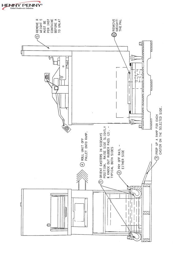
5.Cut and remove the metal bands holding the fryer to the pallet.
All counterweights must be loaded before unlatching lid, or personal injury could result.
6.Remove the fryer from the pallet.
Take care when moving the fryer to prevent personal injury. The fryer weighs approximately 758 lbs.
(344 Kg).
2-1 |
803 |
|
Model PFE590/592 |
2-2. UNPACKING |
7. Remove the counterweights from the pallet, which are |
INSTRUCTIONS |
strapped to the pallet, under the fryer. |
(Continued) |
|
Do not drop. The counterweights weigh approximately 18 lbs. (8.1 kg.) each. Handle with care, or personal injury could result.
8.Remove rear service cover.
9.Load the seven weights into the counterweight assembly. See page 2-4.
10.Replace rear service cover.
To avoid personal injury and assure safe operation of unit, rear service cover must be in place.
11.Cut warning tags from the lid assembly. The lid may now be unlatched.
12.Remove the accessories from inside the filter drain pan.
13.Prepare the deadweight valve for operation
The metal shipping support is placed within the deadweight assembly housing to protect the deadweight orifice and deadweight during shipment. This support must be removed prior to installation and start-up.
A.Unscrew the deadweight cap.
B.Remove the deadweight.
C.Remove and discard the metal packing support.
D.Clean the deadweight orifice with a dry cloth.
E.Carefully place deadweight over deadweight orifice. Replace deadweight cap, finger tight.
13.Remove the protective paper from the fryer cabinet. Clean exterior surface with a damp cloth.
404 |
2-2 |
Model PFE590/592
Optional Ramp Unloading
2-3 |
1103 |

Model PFE590/592
404 |
2-4 |
|
|
|
Model PFE590/592 |
2-3. SELECTING THE |
The proper location of the fryer is very important for operation, |
||
|
LOCATION |
speed, and convenience. Choose a location which will provide |
|
|
|
|
easy loading and unloading without interfering with the final assem- |
|
|
|
bly of food orders. Operators have found that frying from raw to |
|
|
|
finish, and holding the product in a warmer provides fast continuous |
|
|
|
service. Landing or dumping tables should be provided next to at |
|
|
|
least one side of the fryer. Keep in mind the best efficiency will be |
|
|
|
obtained by a straight line operation, i.e. raw in one side and finish |
|
|
|
out the other side. Order assembly can be moved away with only |
|
|
|
a slight loss of efficiency. To properly service the fryer, 24 inches |
|
|
|
(60.96 cm) of clearance is needed on all sides of the fryer. Access |
|
|
|
for servicing can be attained by removing a side panel. |
To avoid fire and ruined supplies, the area under the fryer should not be used to store supplies.
To prevent severe burns from splashing hot shortening, position and install fryer to prevent tipping or movement. Restraining ties may be used for stabilization.
2-4. LEVELING THE FRYER |
For proper operation, level the fryer from side to side and front to |
|
back, using level on the flat areas around the frypot collar. |
FAILURE TO FOLLOW THESE LEVELING
INSTRUCTIONS CAN RESULT IN SHORTENING
OVERFLOWINGTHE FRYPOTWHICH COULD
CAUSE SERIOUS BURNS, PERSONAL INJURY,
FIREAND/OR PROPERTY DAMAGE.
2-5 |
703 |
|
Model PFE590/592 |
2-5. VENTILATION OF FRYER |
The fryer should be located with provision for venting into |
|
adequate exhaust hood or ventilation system. This is essential |
|
to permit efficient removal of steam exhaust and frying odors. |
|
Special precaution must be taken in designing an exhaust canopy to |
|
avoid interference with the operation of the fryer. We recommend |
|
you consult a local ventilation or heating company to help in design- |
|
ing an adequate system. |
|
Ventilation must conform to local, state, and national codes. |
|
Consult your local fire department or building authorities. |
2-6. ELECTRICAL |
The electric fryer requires 208 or 240 volt, three phase, 50/60 |
REQUIREMENTS |
Hertz service. The power cord may be already attached to the |
|
fryer, or provided at installation. Check the data plate mounted just |
|
above the lid, on the left side of the back shroud, to determine the |
|
correct power supply. |
This fryer must be adequately and safely grounded (earthed) or electrical shock could result. Refer to local electrical codes for correct grounding (earthing) procedures or in absence of local codes, with The National Electrical Code, ANSI/NFPANo. 70-(the current edition). In Canada, all electrical connections are to be made in accordance with CSA C22.1, Canadian Electrical Code Part 1, and/or local codes.
To avoid electrical shock, this appliance must be equipped with an external circuit breaker which will disconnect all ungrounded (unearthed) conductors. The main power switch on this appliance does not disconnect all line conductors.
A separate disconnect switch with proper capacity fuses or breakers must be installed at a convenient location between the fryer and the power source. It should be an insulated copper conductor rated for 600 volts and 90o C. For runs longer than 50 feet (15.24 m), use the next larger wire size.
706 |
2-6 |
|
Model PFE590/592 |
2-7. INTERNATIONAL |
Units being used outside the United States may not be shipped |
ELECTRICAL |
with the power cord attached to the unit because of the different |
REQUIREMENTS |
wiring codes. The fryers are available from the factory wired for |
|
208, 240, 380 and 415 volts, 3 phase, 50 Hertz service. A terminal |
|
block is mounted inside the fryer for the cable wiring. Adecal on |
|
the inside of the right side panel will help in the wiring of the unit. |
|
CE units require a minimum wire size of 4mm to be wired to |
|
the terminal block. If a flexible power cord is used, it must be |
|
HO7RN type. |
|
To install the power cord, follow these procedures: |
|
1. Remove the right side panel of the unit. |
|
2. Install the cord, with a strain relief, to the junction box. |
|
3. Attach the wires to the terminal block according to the wiring |
|
diagram on the side panel. |
|
4. Pull the slack out of the cord and thread it down through the |
|
the clamp on the frame, at the rear, left leg of fryer. Then run |
|
the cable under the frame and out the rear of the fryer, so it |
|
doesn’t interfere with the filter drain pan. |
|
The filter drain pan must be as far back under fryer as |
|
it will go, and the cover in place. Be sure the hole in the |
|
cover lines up with the drain before opening the drain. |
|
Failure to follow these instructions causes splashing of |
|
shortening and could result in personal injury. |
|
5. Wiring the fryer is now complete. |
2-7 |
703 |
 Loading...