


EEG-244
TECHNICAL
MANUAL
REGISTER WARRANTY ONLINE AT WWW.HENNYPENNY.COM
Evolution Elite™ Gas Open Fryer
MODEL
EEG-241
EEG-242
EEG-243
EEG-244


Model EEG-241, 242, 243, 244
i
Aug. 2014
TABLE OF CONTENTS
Section Page
Section 1. TROUBLESHOOTING ................................................................................... 3
1-1 Introduction .................................................................................................. 3
1-2 Safety ............................................................................................................ 3
1-3 Troubleshooting ............................................................................................ 4
1-4 Error Code Table ..........................................................................................7
Section 2. INFO & FILTER BUTTON STATS ................................................................. 10
2-1 INFO Button Stats ........................................................................................ 10
2-2 FILTER Button Stats .................................................................................... 10
Section 3. INFORMATION MODE ............................................................................... 11
3-1 Information Mode Details .............................................................................11
Section 4. PRODUCT PROGRAM MODE ................................................................... 17
4-1 Modifying Product Settings ........................................................................... 17
Section 5. LEVEL 2 PROGRAMMING ........................................................................... 20
5-1 Special Program Mode ...................................................................................20
5-2 Clock Set ........................................................................................................ 29
5-3 Data Logging, Heat Control, Tech, Stat & Filter Control Modes .................. 29
5-4 Tech Mode ...................................................................................................... 30
5-5 Stats Mode ...................................................................................................... 36
5-6 Do Not Disturb ...............................................................................................37
Section 6. MAINTENANCE SECTION ...................................................................................... 38
6-1 Introduction .............................................................................................................. 38
6-2 Maintenance Hints ................................................................................................... 38
6-3 Preventive Maintenance ........................................................................................... 38
6-4 Control Panel and Menu Card Replacement ............................................................ 39
6-5 High Temperature Limit Control ............................................................................. 40
6-6 Main Power switch................................................................................................... 41
6-7 Probe Replacement .................................................................................................. 42

Model EEG-241, 242, 243, 244
ii
Aug. 2014
Section 6. MAINTENANCE SECTION (Continued)
6-8 Solenoid Valves .............................................................................................. 45
6-9 Filter Pump & Motor ...................................................................................... 48
6-10 JIB Pump ........................................................................................................ 50
6-11 Blower Replacement ...................................................................................... 51
6-12 Filter Beacon .................................................................................................. 52
6-13 Air Pressure Switches ..................................................................................... 53
6-14 Pilot Replacement .......................................................................................... 54
Section 7. PARTS SECTION
7-1 Parts ................................................................................................................ 63
TABLE OF CONTENTS
Section Page
Model EEG-241, 242, 243, 244
3
Aug. 2014
This section provides troubleshooting information in the form
of an easy to read table.
If a problem occurs during the rst operation of a new fryer,
recheck the installation per the Installation Section of this
manual.
Before troubleshooting, always recheck the operation
procedures per Section 3 of this manual.
SECTION 1. TROUBLESHOOTING
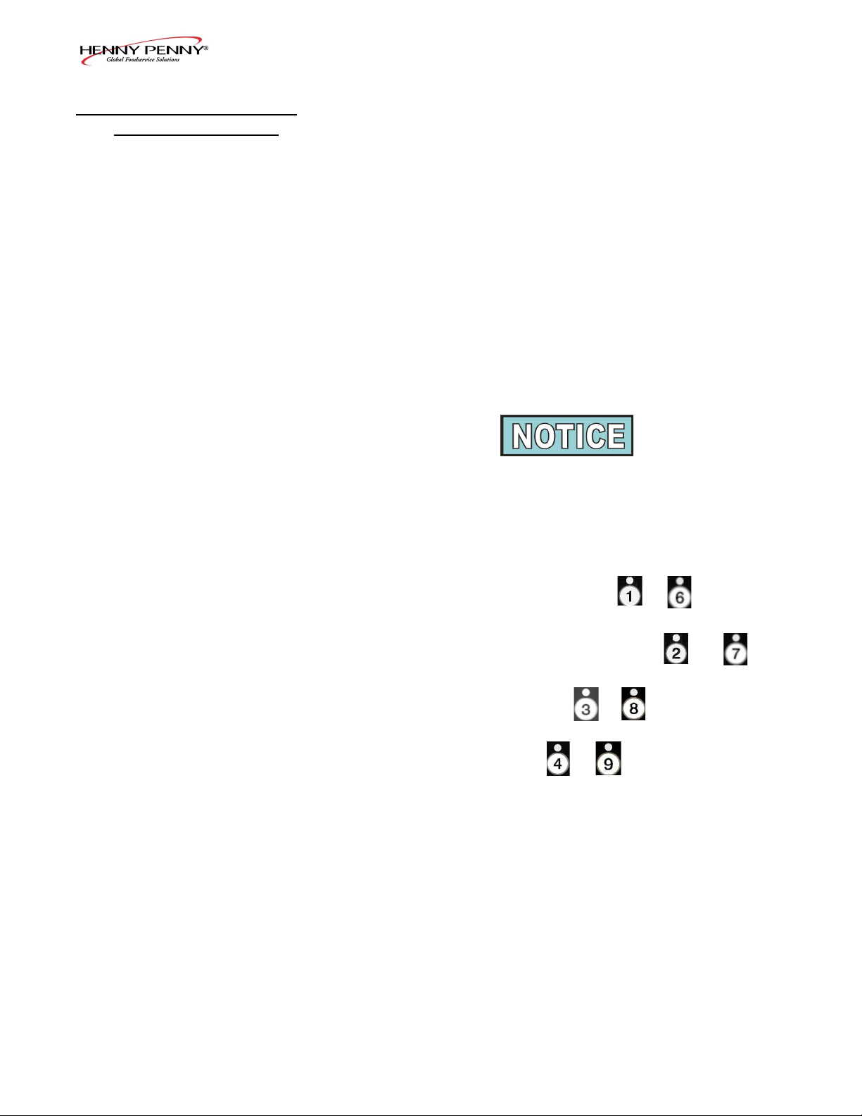
Where information is of particular importance or safety related,
the words DANGER, WARNING, CAUTION, and NOTICE
are used. Their usage is described below.
SAFETY ALERT SYMBOL is used with DANGER,
WARNING, or CAUTION which indicates a personal
injury type hazard.
NOTICE is used to highlight especially important
information.
CAUTION used without the safety alert symbol indicates a
potentially hazardous situation which, if not avoided, may
result in property damage.
CAUTION indicates a potentially hazardous situation
which, if not avoided, may result in minor or moderate
injury.
WARNING indicates a potentially hazardous situation
which, if not avoided, could result in death or serious
injury.
DANGER INDICATES AN IMMINENTLY
HAZARDOUS SITUATION WHICH, IF NOT
AVOIDED, WILL RESULT IN DEATH OR SERIOUS
INJURY.
1-2. SAFETY
1-1. INTRODUCTION

Model EEG-241, 242, 243, 244
4
Aug. 2014
To isolate a malfunction, proceed as follows:
1. Clearly dene the problem (or symptom) and when it
occurs.
2. Locate the problem in the Troubleshooting table.
3. Review all possible causes. Then, one-at-a-time work
through the list of corrections until the problem is solved.
4. Refer to the maintenance procedures in the Maintenance
Section to safely and properly make the checkout and repair
needed.
1-3. TROUBLESHOOTING
If maintenance procedures are not
followed correctly, injuries and/or
property damage could result.
Model EEG-241, 242, 243, 244
5
Aug. 2014
Problem Cause Correction
POWER switch ON
but fryer completely
inoperative
• Open circuit • Plug fryer in
• Check breaker or fuse at supply box
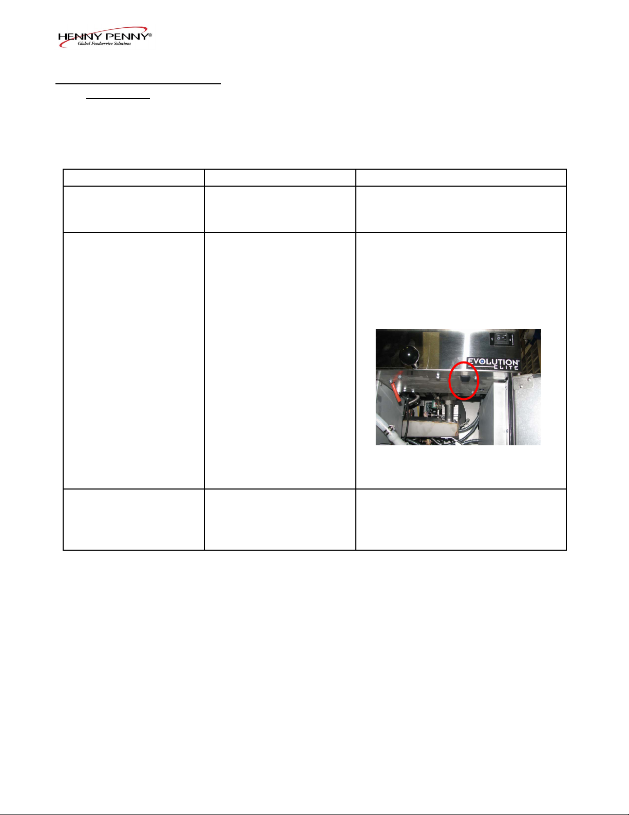
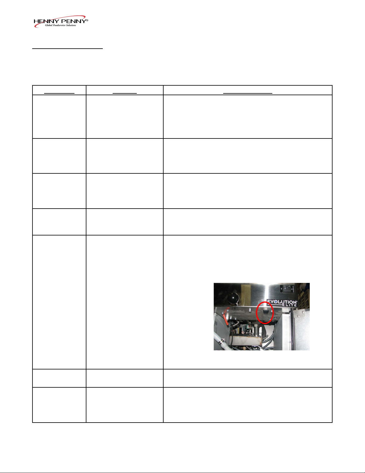
“E-10”
• Hight limit
Let unit cool down (15-20 minutes),
push up on metal reset button under
right side of the controls; if high limit
does not reset, high limit must be
replaced
Vat is under-lled • JIB is low or empty
• JIB oil line is clogged or
collapsed
• Filter pan needs cleaned
• Fill the JIB
• Check JIB line
• Clean lter pan and change paper or
pad
7-1. TROUBLE SHOOTING
(Continued)
Model EEG-241, 242, 243, 244
6
Aug. 2014
Problem Cause Correction
Oil foaming or boiling over
top of vat
• Water in oil
• Improper or bad oil
• Improper ltering
• Improper rinsing after
cleaning the vat
• Drain and clean oil
• Use recommended oil
• Refer to ltering procedures
• Clean and rinse vat and then dry thoroughly
Oil will not drain from vat • Drain valve clogged with
crumbs
• Drain trough clogged
• Open valve, force cleaning brush through
drain
• Remove right side panel and remove plug
from end of trough and clean trough
Filter motor runs but pumps
oil slowly
• Filter line connections loose
• Filter paper or pad clogged
• Filter not reassembled
correctly
• Tighten all lter line connections
• Change lter paper or pad
• Refer to assembly instructions on inside door
Bubbles in oil during entire
ltering process
• Filter pan not completel
engaged
• Filter pan clogged
• Damaged O-ring on lter line
receiver on fryer
• Make sure lter pan return line is pushed
completely into the receiver on the fryer
• Clean pan and change paper or pad
• Change O-ring
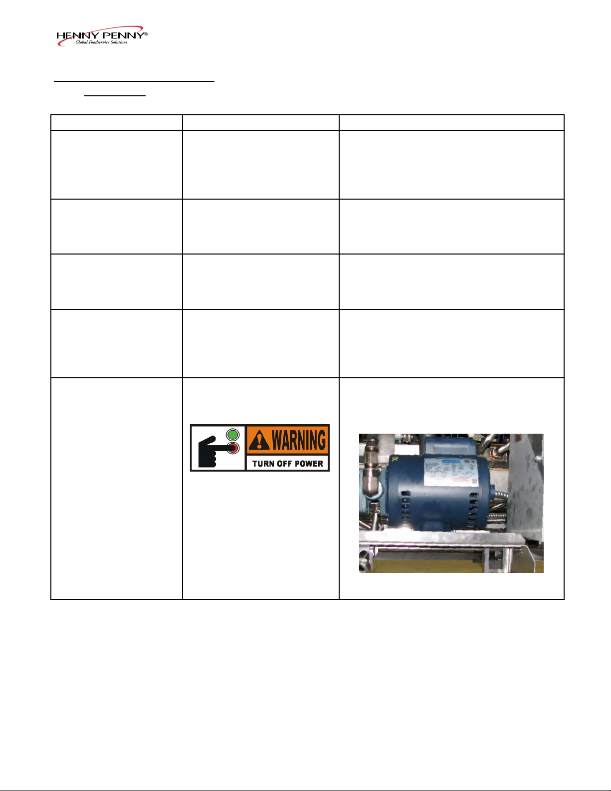
Filter motor will not run • The thermal reset button on
the rear of the pump motor is
tripped
• Allow time for the motor to cool and
then, using a screwdriver, press hard
against the button until it clicks
To prevent burns caused by
splashing shortening, turn
the unit’s POWER switch
to the OFF position before
resetting the lter pump
motor’s manual reset
protection device.
7-1. TROUBLE SHOOTING
(Continued)
Model EEG-241, 242, 243, 244
7
Aug. 2014
1-4. ERROR CODES
In the event of a control system failure, the digital display
shows an error message. The message codes are shown in the
DISPLAY column below. A constant tone is heard when an er-
ror code is displayed, and to silence this tone, press any button.
DISPLAY CAUSE CORRECTION
“E-4”
• Control board
overheating
Turn switch to OFF position, then turn switch back
to ON; if display shows “E-4”, the control board is
getting too hot; check the louvers on each side of
the unit for obstructions
“E-5”
• Oil overheating
Turn switch to OFF position, then turn switch back
to ON; if display shows “E-5”, the heating circuits
and temperature probe should be checked
“E-6A”
• Temperature probe
open
Turn switch to OFF position, then turn switch back
to ON; if display shows “E-6A”, the temperature
probe should be checked
“E-6B”
• Temperature probe
shorted
Turn switch to OFF position, then turn switch back
to ON; if display shows “E-6B”, the temperature
probe should be checked
“E-10”
• Hight limit
Let unit cool down (15-20 minutes), push up on
metal reset button under right side of the controls;
if high limit does not reset, high limit must be
replaced
“E-15” • Drain switch Make sure drain knob is completely pushed-in; if E-15
persists, have drain switch checked
“E-18-A”
“E-18-B”
“E-18-C”
• LH level sensor open
• RH level sensor open
• Both sensors open
Turn switch to OFF position, then turn switch back to
ON; if display still indicates a failed sensor, have the
connectors checked at the control board; have sensor
checked & replace if necessary
Model EEG-241, 242, 243, 244
8
Aug. 2014
“E-20-A”
“FAN SENSOR
STUCK
CLOSED”
• Pressure Switch
failure
• Wiring problem
• I/O board failure
• If fan is not running, have pressure switch
checked; should be open circuit if no air
pressure
• If fan is running, wiring error, or relay on I/O board
closed
“E-20-B”
“NO DRAFT”
“CHECK FAN”
• Pressure switch
failure/ hose loose
• Draft fan failure/ low
voltage
• Flue or hood
obstruction
• Press power button to vat off and back on again,
if E-20-B persists, have pressure switch checked;
should be open circuit if no air pressure; make sure
hose is connected to fan and pressure switch
• Have draft fan checked; low voltage going to fan
• Check the fryer ue and hood system for obstructions
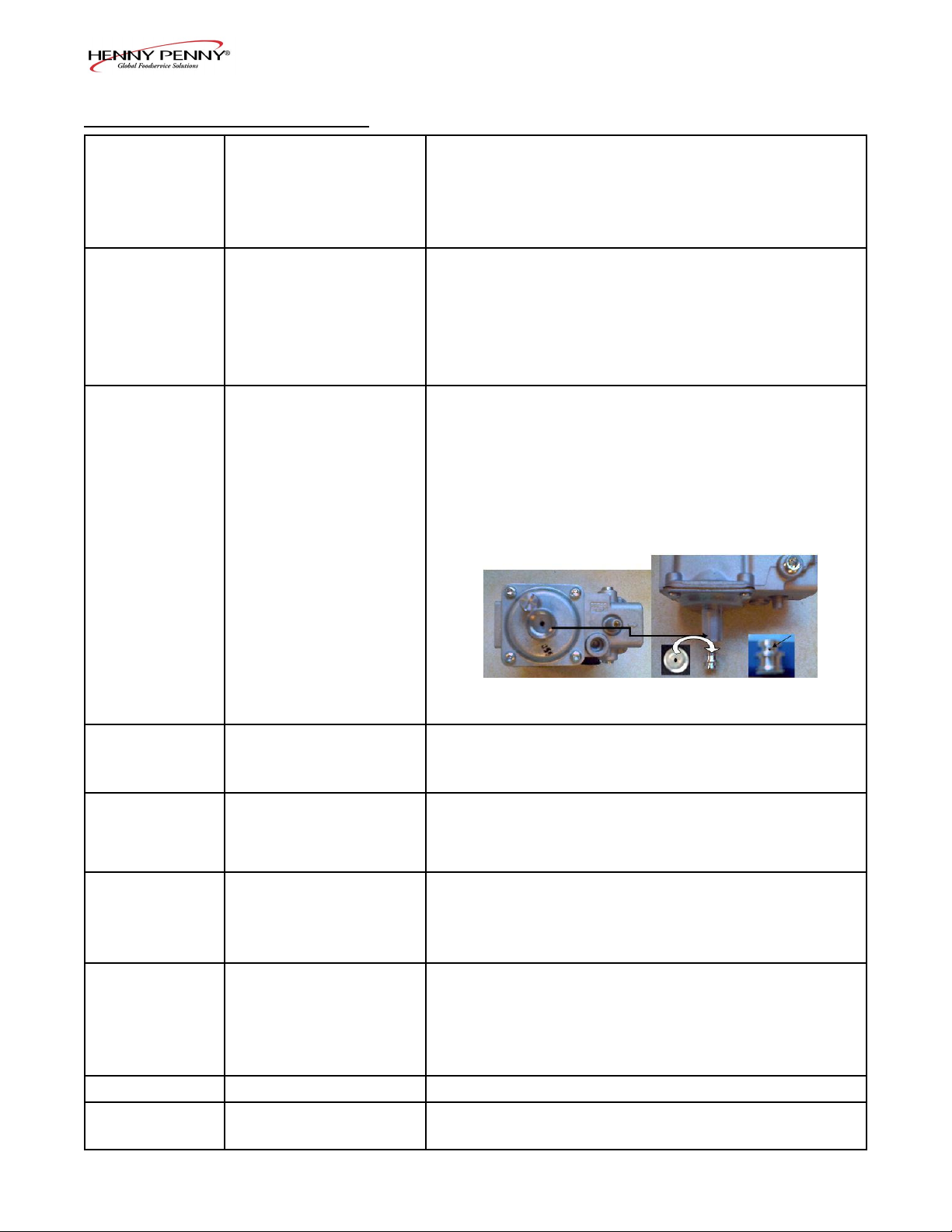
“E-20-D”
“IGNITION”
“FAILURE”
• Failure to ignite/ no
ame sense
• Plugged atmospheric
equalization hole
in regulator cap
resulting in pilot
ame slowly fading
• Press power button to vat off and back on again, if
E-20-D persists, check gas line connections; check
gas shutoff valve; check ignition module; check gas
valve; check ame sensor gap; check gas valve, and
check ignition module wiring
• Clear obstruction from hole
“E-21”
• Slow heat recovery • Have a certied service technician check the fryer for
correct voltage to the unit; have heat circuit checked;
have unit checked for loose or burnt wire
“E-22”
“NO HEAT”
“CHECK GAS
VALVE”
• Burner not igniting
• Have gas valve and heat circuit checked
“E-41 “ / “E-46”
• Programming failure • Press power button to vat off and back on again,
if any of the error codes, have the controls re-
initialized; if error code persists, have the control
board replaced
“E-47”
• Analog converter
chip or 12 volt
supply failure
• Press power button to vat off and back on again,
if “E-47” persists, have the I/O board, or the
PC board replaced; if speaker tones are quiet,
probably I/O board failure; have the I/O board
replaced
“E-48”
• Input system error
• Have PC board replaced
“E-54-C”
• Temperature input
error
• Turn switch to OFF, then back to ON; have
control PC board replaced if “E-54C” persists
1-4. ERROR CODES (Continued)
Model EEG-241, 242, 243, 244
9
Aug. 2014
1-4. ERROR CODES (Continued)
“E-60”
“FILTER IN USE”
• AIF PC board not
communitcating with
control PC board
• Press power button to turn vat off, wait 15 seconds,
and turn back on again. If “E-60” persists, have
connector between the PC boards checked; replace
AIF PC board or control PC board, if necessary
“E-70C”
• Drain valve jumper
wire missing or
disconnected
• Have the jumper wire checked on the PC board at
drain switch interlock position
“E-83-A”
• Pressure too high • Check lter system in Vat #1
“E-83-B”
• Pressure too high
• Check lter system in Vat #2
“E-83-C”
• Pressure too high • Check lter system in Vat #3
“E-83-D”
• Pressure too high
• Check lter system in Vat #4
“E-83-E”
• Pressure too high • Check lter system in Vat #5
“E-83-J”
• Bulk JIB FILL
switch ON when
pressure too high
• CheckJIBllvalves
“E-83-R”
• Bulk Dispose switch
ON when pressure
too high
• Check Bulk Dispose quick-disconnect behind
fryer
“E-93-1”
“24 VDC SUPPLY
TRIPPED”
• Autolift motor
malfunction or
failure
• If AutoLift feature is not operating, have each of the
AutoLift motors checked.
Model EEG-241, 242, 243, 244
10
Aug. 2014
SECTION 2. INFO & FILTER BUTTON STATS
2-1. INFO BUTTON STATS
Actual Oil Temperature
1. Press and the actual oil temperature shows in the
display, for each vat.
Set-point Temperature
1. Press twice and SP shows in the display, along with
the set-point (preset) temperature of each vat.
Recovery Information for each Vat
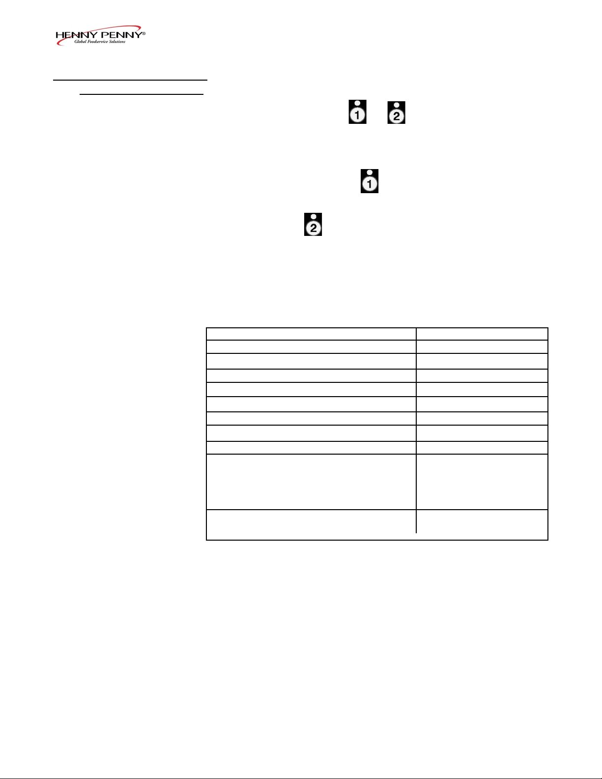
1. Press 3 times and REC shows in the left display and
the recovery time that oil temperature went from 250°F
(121°C) to 300°F (149°C) shows in the right display. For
example, means it took 5 minutes and
30 seconds for the oil temperature to recover to 300°F
(149°C) from 250°F (121°C).
Cook Cycles Remaining before Filtering
1. Press and release either button and the left display
shows “COOKSREMAINING” and the right display shows
the number of cook cycles before the next auto lter. For
example.
means after 3 more cook cycles on the left vat, the controls
asks the operator if they are ready to lter or not. But, 6
more cook cycles remain on the right vat.
Time and Date
2. Press either twice and ‘FILTERED” shows in the
diplays, along with the time-of-day and date of the last
lter.
Filter Pad Hours
3. Press either three times and ‘FLTR PAD XX HRS”
shows in the diplays.
REC 5:30
2-2. FILTER BUTTON STATS
REMA INING
3 6
If no buttons are pressed within 5 seconds in
any of stats modes, the controls revert back to
normal operation.
Model EEG-241, 242, 243, 244
11
Aug. 2014
SECTION 3. INFORMATION MODE
This historic information can be recorded and used for
operational and technical help and allows you to view the
following:
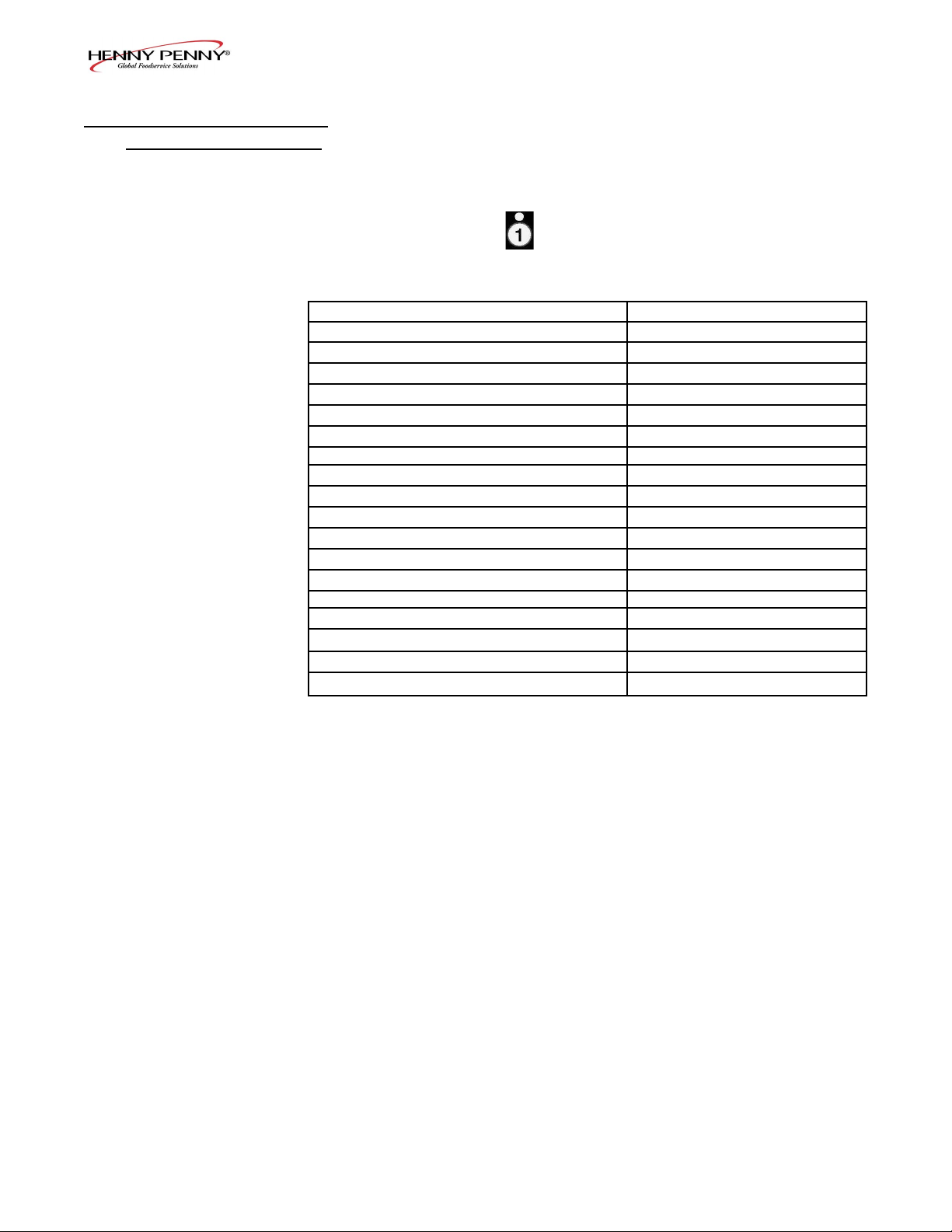
1. E-LOG (error code log)
Press and buttons at the same time and “*INFO
MODE*” shows in the display, followed by “1. E-LOG”.
Press ▼ and “A. (date & time) *NOW* show in displays.
This is the present date and time.
Press ▼ and if a error was recorded, “B. (date, time, and
error code information)” shows in display. This is the latest
error code that the controls recorded.
Press ▼ and the next latest error code information can be seen.
Up to 10 error codes (B to K) can be stored in the E-LOG
section.
3-1. INFORMATION MODE
DETAILS
• 1. E-LOG • 9. CPU TEMP
• 2. LAST LOAD • 10. COMMUNICATION INFO
• 3. DAILY STATS • 11. ANALOG INFO
• 4. OIL STATS • 12. ACTIVITY LOG
• 5. REVIEW USAGE • 13. OIL LEVELS
• 6. INPUTS • 14. PUMP VALVE INFO
• 7. OUTPUTS • 15. AIF INFO
• 8. OIL TEMP
Not all Information Mode functions are discussed in this
section. To ensure proper operation of fryer, please consult
Henny Penny Corp. before changing any of these settings. For
more information on these functions, contact Technical Support
at 1-800-417- 8405, or 1-937-456-8405.
Press and to exit Information Mode at any time.
Model EEG-241, 242, 243, 244
12
Aug. 2014
2. LAST LOAD (Information on recent cook cycles)
Press ► and “2. LAST LOAD” show in displays.
Press a timer button or for the product you want to
view the cook data and the LED ashes.
Press ▼ button to start viewing the cook data.
For example, if the left LED is ashing, “PRODUCT
FRY L1” show in displays.
If the right LED is ashing, “PRODUCT FRY R2” show
in displays.
Press ▼ button to start viewing the cook data.
3-1. INFORMATION MODE
DETAILS (Continued)
FUNCTION DISPLAY EX:
Product (Last product cooked) PRODUCT FRY L1
Time of day the last Cook Cycle was started STARTED FEB 4
2:25P
Actual Elapsed cook Time (Real seconds) ACTUAL TIME 1:06
Programmed cook Time PROG TIME 1:00
Max Temp during Cook Cycle MAX TEMP 350°F
Min Temp during Cook Cycle MIN TEMP 313°F
Avg Temp during Cook Cycle AVG TEMP 322°F
Heat On (percentage) during Cook Cycle HEAT ON 45%
Ready? (Was fryer Ready before start?) READY? YES
When Cook Cycle was stopped: Early QUIT AT 0:10 REM
After complete Cook Cycle OR
*DONE* +6 SEC
Difference (%) between actual and ACT/PROG 1%
programmed cook time
Model EEG-241, 242, 243, 244
13
Aug. 2014
3-1. INFORMATION MODE
DETAILS (Continued)
3. DAILY STATS (Operational info of fryer for last 7 days)
Press ► and “3. DAILY STATS” show in displays.
Press ▼ button to start viewing the cook data.
Press the right to view data for other days of week.
Day this data was recorded for APR-30 TUE*
Number of Hours:Minutes the fryer was on (L/R) ON HRS TUE* 3:45
Number of times ltered (L/R) FILTERED TUE* 4
Number of times lter skipped (L/R) SKIPPED TUE* 4
Number of times oil added (L/R) ADD OIL TUE* 4
Number of times oil discarded (L/R) DISPOSE TUE* 0
Oil temperature recovery time (L/R) RECOVERY TUE*1:45
Total number of cook cycles that day (L/R) TOT CK TUE* 38
Number of cycles stopped before *DONE* QUIT CK TUE* 2
Cook Cycles for Product #1 TUE* COOK -1- 17
Cook Cycles for Product #2 TUE* COOK -2- 9
Cook Cycles for Product #3 TUE* COOK -3- 5
Cook Cycles for Product #4 TUE* COOK -4- 0
Cook Cycles for Product #5 TUE* COOK -5- 0
Cook Cycles for Product #6 TUE* COOK -6- 6
Cook Cycles for Product #7 TUE* COOK -7- 0
Cook Cycles for Product #8 TUE* COOK -8- 0
Cook Cycles for Product #9 TUE* COOK -9- 1
Cook Cycles for Product #0 TUE* COOK -0- 0
FUNCTION DISPLAY EX:
Model EEG-241, 242, 243, 244
14
Aug. 2014
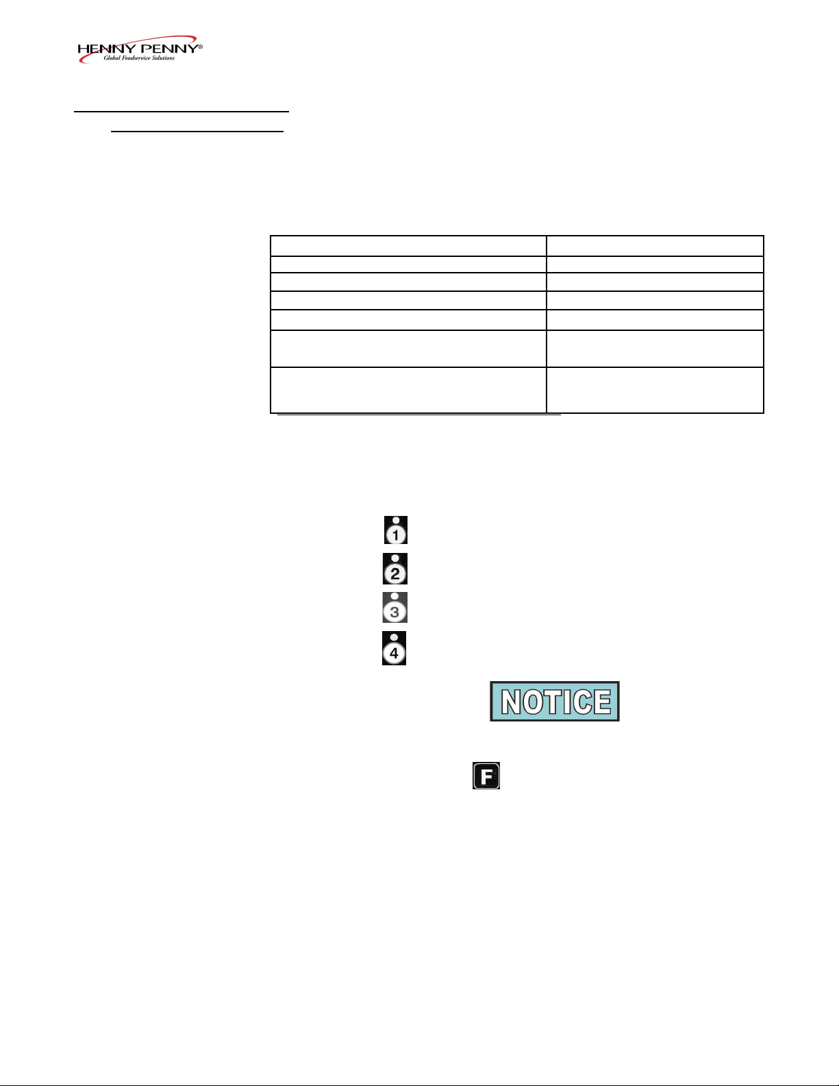
4. OIL STATS
(info of current oil and avg. of last 4 batches of oil)
Press ► and “4. OIL STATS” show in displays.
Press ▼ button to start viewing the cook data.
Press and hold a product button (1 to 4) to view the data from
one of the previous 4 batches of oil used.
Press to view oldest oil data: Ex: OIL-4 14 DAYS
Press to view 3rd oldest oil data: Ex: OIL-3 12 DAYS
Press to view 2nd oldest oil data: Ex: OIL-2 15 DAYS
Press to view previous batch of oil: Ex: OIL-1 13 DAYS
3-1. INFORMATION MODE
DETAILS (Continued)
Start date of new oil NEW OIL MAR-23
Number of days oil in use (L/R) OIL USE 4 DAYS
Number of lters on this oil (L/R) FILTERED 4
Number of times lter skipped (L/R) SKIPPED 0
Number of cook cycles on this oil (L/R) TOT CK 38
Average number of days per oil change (L/R) AVG DAYS
PER OIL CHANGE 13.8 DAYS
Average number cook cycles per oil change (L/R) AVG CKS PER
OIL CHANGE 388 CKS
FUNCTION DISPLAY EX:
To obtain the most accurate oil information, use
the “3.DISPOSE” step in the Filter Menu (press
and hold ) to drain the oil from the vat.
Model EEG-241, 242, 243, 244
15
Aug. 2014
5. REVIEW USAGE
(accumulated info since the data was reset)
Press ► and “5. REVIEW USAGE” show in displays.
Press ▼ button to start viewing the cook data.
FUNCTION DISPLAY EX:
Day the usage data was previously reset SINCE APR-19 3:00P
Number of Hours the fryer was on (L/R) ON HRS 4
Number of times ltered (L/R) FILTERED 4
Number of times lter skipped (L/R) SKIPPED 0
Number of times oil added (L/R) ADD OIL 4
Number of times oil discarded (L/R) DISPOSE 1
Total number of cook cycles (L/R) TOT CK 38
Number of cycles stopped before *DONE* QUIT CK 2
Cook Cycles for Product #1 COOK -1- 17
Cook Cycles for Product #2 COOK -2- 9
Cook Cycles for Product #3 COOK -3- 5
Cook Cycles for Product #4 COOK -4- 0
Cook Cycles for Product #5 COOK -5- 0
Cook Cycles for Product #6 COOK -6- 6
Cook Cycles for Product #7 COOK -7- 0
Cook Cycles for Product #8 COOK -8- 0
Cook Cycles for Product #9 COOK -9- 1
Cook Cycles for Product #0 COOK -0- 0
Reset usage data:
Enter the Usage Code - 1, 2, 3 RESET USAGE /
on this step to zero out all the ENTER CODE ------
usage information
3-1. INFORMATION MODE
DETAILS (Continued)
Model EEG-241, 242, 243, 244
16
Aug. 2014
6. INPUTS
Press ► and “6. INPTS” and “HDF” show in displays.
H = HIGH LIMIT - If “H” is present, the high limit is good. If “-”
shows then the high limit is tripped out (overheated) or discon-
nected.
D = DRAIN SWITCH - If “D” is present, the drain handle (when
applicable) is closed. If “-” shows then the drain is open or the
switch is faulty.
F =FAN (PRESSURE SWITCH) - If “F” is present, the pressure
switch is good. If “-” shows in the display, the switch is faulty.
Press ▼ button and an underscore (“_”) indicates the input is not
presently detected. A Checkmark (“
√” ) indicates the signal is
detecting a normal input. A blinking (“X”) indicates the signal is
presently detected, but is detected as a half-wave (partially failed)
input.
The H, D, F signals above are wired in series. The rst signal miss-
ing out of this sequence l generally causes all signals to the right of it
to be missing as well.
7. OUTPUTS
Press ► and “7. OUTP” and “F-S-I-H-” show in displays.
F = FAN (PRESSURE SWITCH)- Press or to open and
close the pressure switches
S = SAFETY GAS VALVE (if available) - Press or to
open and close the gas safety valves
I = IGNITION MODULE - Press or to open and
close the outputs on the ignition modules
H = HEAT OUTPUTS - Press or to turn on and off the
heating outputs (ex: gas valve)
8. OIL TEMPERATURE
Press ► and “8.OIL TMP” shows in the left display and the oil
temperature shows in the right display.
9. CPU TEMPERATURE
Press ► and “9.CPU TMP” shows in the left display and the
current PC board temperature shows in the right display.
3-1. INFORMATION MODE
DETAILS (Continued)
Model EEG-241, 242, 243, 244
17
Aug. 2014
This mode allows you to program the following:
1. Press and hold button until “PROG” shows in the
display, followed by “ENTER CODE”.
2. Enter code 1, 2, 3 (rst 3 product buttons). “PRODUCT”
and “PROGRAM” show in the displays, followed by
“SELECT PRODUCT’ and “-P 1-” (ex: NUG).
Change Product Names
3. Use the ▲and ▼ buttons to scroll through the 40 products,
or press the desired product button.
4. Press ►button and “NAME” shows in the left display
and the product (ex: NUGGETS) shows in the right display.
5. Press √ button and the rst letter in the name ashes.
Press a product button and the ashing letter changes to
the rst letter under the product button that was pressed.
For example, if is pressed, the ashing letter changes
to an “A”.
Press the same button again and the ashing letter changes
to a “B”. Press it again and the ashing letter changes to
a “C”. Once the desired letter shows in the display, press
► button to continue to the next letter and repeat the
procedure.
Press and hold the right X button to exit Program Mode, or
press ► button to continue on to “COOK TIME”.
Assign Button
6. Press ► button until “ASSIGN BTN” shows in the
display, along with the product (ex: NUGGETS). If this
product already has a product button assigned to it, that
LED will be lit. To assign other product buttons to that
product, press and hold the product button for 3 seconds
and that LED stays lit. To remove a product from a button,
press and hold the product button with a lit LED and the
LED goes out.
SECTION 4. PRODUCT PROGRAM MODE
4-1. MODIFYING PRODUCT
SETTINGS
• Include in Filter Count (Global)
• Filter at X no. of loads (Mixed)
• Load Compensation
• Load Compensation Reference
• Full Heat
• PC Factor
• Change Product Name
• Assign Button
• Change Times & Temp
• Change Cook ID
• Alarms
• Quality Timers

Model EEG-241, 242, 243, 244
18
Aug. 2014
To Change Times and Temperatures
7. Press ► button until “COOK TIME” shows in the display,
and then use the product buttons, or the ▲ and ▼buttons,
to change the time in minutes and seconds, to a maximum
of 59:59.
8. Press ► button and “TEMP” shows in the display, along
with the preset temperature on the right side of the display.
Press the product buttons, or the ▲ and ▼ buttons, to
change the temperature. The temperature range is 190°F
(88°C) to 375°F (191°C).
Cook ID Change
9. Press ► button until “COOK ID” shows in the display
along with the product ID. For example, NUG would be
the ID for nuggets. Use the product buttons, or the ▲ and
▼ buttons, to change the ID.
Alarms (1 & 2)
10. Press ► button until “ALRM 1” shows in the left display,
and an alarm time in the right display. Press the product
buttons, or the ▲ and ▼buttons, to set an alarm.
Ex., If a Cook Cycle was set at 3 minutes, and an alarm
was to go off after 30 seconds into the Cook Cycle, “2:30”
would be set in the display at this time. When the timer
counts down to 2:30 the alarm sounds.
After the alarm time is set, press ► button and “ALRM
2” shows in the display, and a second alarm can be
programmed.
Quality Timer (hold time)
11. Press ► button until “QUAL TMR” shows in the display
along with the preset holding time. Press the product
buttons, or the ▲ and ▼ buttons,to adjust holding time, up
to 59:59.
Global Filter Tracking
Include in Filter Count
12. Press ► button until “INCL IN FLTR CNT” ashes in
the display along with “YES” or “NO”. Using ▲ and ▼
buttons, change the display to “YES” if that product’s Cook
Cycles are to be counted as part of the recommended lter
process. Set to “NO” if it is not to be included. Mixed
Filter Tracking
4-1. MODIFYING PRODUCT
SETTINGS (Continued)
 Loading...