


Henny Penny
Pressure Fryers
Model 500
Model 600
Computron 2000 Controls
OPERATOR’S MANUAL
REGISTERWARRANTYONLINEATWWW.HENNYPENNY.COM

Model 500/600
LIMITED WARRANTY FOR HENNY PENNY EQUIPMENT
Subject to the following conditions, Henny Penny Corporation makes the following limited warranties to the original purchaser only for Henny Penny appliances and replacement parts:
NEW EQUIPMENT: Any part of a new appliance, except baskets, lamps, and fuses, which proves to be defective in material or workmanship within two (2) years from date of original installation, will be repaired or replaced without charge F.O.B. factory, Eaton, Ohio, or F.O.B. authorized distributor. Baskets will be repaired or replaced for ninety (90) days from date of original installation. Lamps and fuses are not covered under this Limited Warranty. To validate this warranty, the registration card for the appliance must be mailed to Henny Penny within ten (10) days after installation.
FILTER SYSTEM: Failure of any parts within a fryer filter system caused by the use of the non-OEM filters or other unapproved filters is not covered under this Limited Warranty.
REPLACEMENT PARTS: Any appliance replacement part, except lamps and fuses, which proves to be defective in material or workmanship within ninety (90) days from date of original installation will be repaired or replaced without charge F.O.B. factory, Eaton, Ohio, or F.O.B. authorized distributor.
The warranty for new equipment covers the repair or replacement of the defective part and includes labor charges and maximum mileage charges of 200 miles round trip for a period of one (1) year from the date of original installation.
The warranty for replacement parts covers only the repair or replacement of the defective part and does not include any labor charges for the removal and installation of any parts, travel, or other expenses incidental to the repair or replacement of a part.
EXTENDED FRYPOTWARRANTY: Henny Penny will replace any frypot that fails due to manufacturing or workmanship issues for a period of up to seven (7) years from date of manufacture. This warranty shall not cover any frypot that fails due to any misuse or abuse, such as heating of the frypot without shortening.
0 TO 3 YEARS: During this time, any frypot that fails due to manufacturing or workmanship issues will be replaced at no charge for parts, labor, or freight. Henny Penny will either install a new frypot at no cost or provide a new or reconditioned replacement fryer at no cost.
3 TO 7 YEARS: During this time, any frypot that fails due to manufacturing or workmanship issues will be replaced at no charge for the frypot only. Any freight charges and labor costs to install the new frypot as well as the cost of any other parts replaced, such as insulation, thermal sensors, high limits, fittings, and hardware, will be the responsibility of the owner.
Any claim must be presented to either Henny Penny or the distributor from whom the appliance was purchased. No allowance will be granted for repairs made by anyone else without Henny Penny’s written consent. If damage occurs during shipping, notify the sender at once so that a claim may be filed.
THEABOVELIMITEDWARRANTYSETSFORTHTHESOLEREMEDYAGAINSTHENNYPENNYFORANYBREACH OFWARRANTYOR OTHER TERM. BUYERAGREES THATNO OTHER REMEDY(INCLUDINGCLAIMS FORANY INCIDENTALORCONSEQUENTIALDAMAGES)SHALLBEAVAILABLE.
The above limited warranty does not apply (a) to damage resulting from accident, alteration, misuse, or abuse; (b) if the equipment’s serial number is removed or defaced; or (c) for lamps and fuses. THE ABOVE LIMITED WARRANTY IS EXPRESSLYINLIEUOFALLOTHERWARRANTIES,EXPRESSORIMPLIED,INCLUDINGMERCHANTABILITYAND FITNESS,ANDALLOTHERWARRANTIESAREEXCLUDED. HENNYPENNYNEITHERASSUMESNORAUTHORIZES ANYPERSONTOASSUMEFORITANYOTHEROBLIGATIONORLIABILITY.
Revised 01/01/07
FM07-219-B
Revised 12-26-07
Model 500/600
This manual should be retained in a convenient location for future reference.
A wiring diagram for this appliance is located on the rear shroud cover of the control panel.
Post in a prominent location, instructions to be followed if user smells gas. This information should be obtained by consulting the local gas supplier.
Do not obstruct the flow of combustion and ventilation air.Adequate clearance must be left all around appliance for sufficient air to the combustion chamber.
The Model 600 Fryer is equipped with a continuous pilot. But Fryer can not be operated without electric power. Fryer will automatically return to normal operation when power is restored.
Keep appliance area free and clear from combustibles.
Improper installation, adjustment, alteration, service, or maintenance can cause property damage, injury, or death. Read the installation, operating, and maintenance
instructions thoroughly before installing or servicing this equipment.
DO NOT STORE OR USE GASOLINE OR OTHER FLAMMABLE VAPORS
AND LIQUIDS IN THE VICINITY OFTHIS ORANY OTHER APPLIANCE. FIRE OR EXPLOSION COULD RESULT.
803

Model 500/600
|
Technical Data for CE Marked Products |
||
Nominal Heat Input: |
Natural (I2H) = 21.1 KW (72,000 Btu/h) |
||
(Net) |
Natural (I2E) = 21.1 KW (72,000 Btu/h) |
||
|
Natural (I2E+) = 21.1 KW (72,000 Btu/h) |
||
|
Natural (I2L) = 21.1 KW (72,000 Btu/h) |
||
|
Liquid Propane (I3P) = 21.1 KW (72,000 Btu/h) |
||
Nominal Heat Input: |
Natural (I2H) = 23.4 KW (80,000 Btu/h) |
||
(Gross) |
Natural (I2E) = 23.4 KW (80,000 Btu/h) |
||
|
Natural (I2E+) = 23.4 KW (80,000 Btu/h) |
||
|
Natural (I2L) = 23.4 KW (80,000 Btu/h) |
||
|
Liquid Propane (I3P) = 22.9 KW (78,000 Btu/h) |
||
Supply Pressure: |
Natural (I2H) = 20 mbar |
||
|
Natural (I |
) = 20 mbar |
|
|
Natural (I2E |
|
) = 20/25 mbar |
|
2E+ |
||
|
Natural (I2L) = 25 mbar |
||
|
Liquid Propane (I3P) = 30 mbar |
||
|
Liquid Propane (I3P) = 37 mbar |
||
|
Liquid Propane (I3P) = 50 mbar |
||
Test Point Pressure: |
Natural (I2H) = 8.7 mbar |
||
|
Natural (I |
) = 8.7 mbar |
|
|
Natural (I2E |
|
) = 8.7/10 mbar |
|
2E+ |
||
|
Natural (I2L) = 10 mbar |
||
|
Liquid Propane (I3P) = 25 mbar |
||
Injector Size: |
Natural (I2H) = 1.04 mm |
||
|
Natural (I ) = 1.04 mm |
||
|
Natural (I2E |
|
) = 1.04 mm |
|
2E+ |
|
|
|
Natural (I2L) = 1.04 mm |
||
|
Liquid Propane (I3P) = 0.66 mm |
||
Restrictor Size: |
Natural (I2E+) = 4.1 mm |
||
This appliance must be installed in accordance with the manufacturer’s instructions and the regulations in force and only used in a suitably ventilated location. Read the instructions fully before installing or using the appliance.

|
|
Model 500/600 |
Section |
TABLE OF CONTENTS |
Page |
|
||
Section 1. INTRODUCTION ....................................................................................................... |
1-1 |
|
1-1. |
Pressure Fryer..................................................................................................... |
1-1 |
1-2. |
Proper Care ........................................................................................................ |
1-1 |
1-3. |
Assistance ........................................................................................................... |
1-1 |
1-4. |
Model Variations ................................................................................................. |
1-1 |
1-5. |
Safety ................................................................................................................. |
1-2 |
Section 2. INSTALLATION ......................................................................................................... |
2-1 |
|
2-1. |
Introduction......................................................................................................... |
2-1 |
2-2. |
Unpacking Instructions ........................................................................................ |
2-1 |
2-3. |
Selecting the Fryer Location ................................................................................ |
2-3 |
2-4 |
Leveling the Fryer................................................................................................ |
2-3 |
2-5. |
Ventilation of Fryer .............................................................................................. |
2-4 |
2-6. |
Gas Supply ......................................................................................................... |
2-5 |
2-7. |
Gas Piping........................................................................................................... |
2-6 |
2-8. |
Gas Leak Test ..................................................................................................... |
2-9 |
2-9. |
Gas Pressure Regulator Setting ............................................................................ |
2-9 |
2-10. |
Gas Pilot & Burner Lighting and Shutdown Procedure.......................................... |
2-9 |
2-11. |
Pilot FlameAdjustment ........................................................................................ |
2-10 |
2-12. |
Pressure RegulatorAdjustment (Gas Only)........................................................... |
2-10 |
2-13. |
Electrical Requirements (Electric Fryer)................................................................ |
2-11 |
2-14. |
Electrical Requirements (Gas Fryer) ..................................................................... |
2-12 |
2-15. |
Checking the Filter Pump..................................................................................... |
2-13 |
2-16. |
Motor Bearings ................................................................................................... |
2-13 |
2-17. |
Operational Checks............................................................................................. |
2-13 |
Section 3. OPERATING INSTRUCTIONS .................................................................................. |
3-1 |
|
3-1. |
Operating Controls .............................................................................................. |
3-1 |
3-2. |
Operating Components........................................................................................ |
3-3 |
3-3. |
Filling orAdding Shortening ................................................................................. |
3-10 |
3-4. |
Care of the Shortening ......................................................................................... |
3-11 |
3-5. |
Basic Operations and Procedures ........................................................................ |
3-12 |
3-6. |
Regular Maintenance Schedule ............................................................................ |
3-15 |
3-7. |
Filter Pump Motor Protector - Manual Reset ....................................................... |
3-15 |
3-8. |
Filtering of Shortening .......................................................................................... |
3-16 |
3-9. |
Filter Pump Problem Prevention........................................................................... |
3-20 |
3-10. |
Changing the Filter Envelope................................................................................ |
3-20 |
3-11. |
Cleaning the Frypot ............................................................................................. |
3-23 |
3-12. |
Cleaning the DeadweightAssembly ...................................................................... |
3-25 |
3-13. |
Operating Instructions for Optional Direct-Connect Shortening System ................. |
3-26 |
3-14. |
Reversing the Lid Gasket ..................................................................................... |
3-27 |
3-15. |
Lid Lubrication .................................................................................................... |
3-28 |
3-16. |
Limit StopAdjustment ......................................................................................... |
3-29 |
3-17. |
Cleaning the Safety ReliefValve ........................................................................... |
3-30 |
3-18. |
Check & Tighten Element Spreader Bars (Models 500 only) ................................ |
3-31 |
108 |
i |

|
|
Model 500/600 |
Section |
TABLE OF CONTENTS (Continued) |
Page |
|
||
Section 4. PROGRAMMING ....................................................................................................... |
4-1 |
|
4-1. |
Introduction......................................................................................................... |
4-1 |
4-2. Time and Set-Point Programming ......................................................................... |
4-1 |
|
4-3. Special Program Mode........................................................................................ |
4-2 |
|
Section 5. TROUBLESHOOTING ............................................................................................... |
5-1 |
|
5-1. |
Troubleshooting Guide ......................................................................................... |
5-1 |
5-2. |
Error Codes ........................................................................................................ |
5-2 |
5-3. |
Error Code Table ................................................................................................ |
5-2 |
GLOSSARY ................................................................................................................ |
G-1 |
|
Distributors List - Domestic and International |
|
|
ii |
1207 |

Model 500/600
SECTION 1. INTRODUCTION
1-1. PRESSURE FRYER
P-H-T
Pressure
Heat
Time
1-2. PROPER CARE
1-3. ASSISTANCE
1-4. MODEL VARIATIONS
The Henny Penny Pressure Fryer is a basic unit of food processing equipment. It has found wide application in institutional and commercial food service operations.
A combination of pressure, heat, and time is automatically controlled to produce the optimum in a tasty, appealing product.
Pressure is basic to this method of food preparation. This pressure is developed from the natural moisture of the food. The patented lid traps this moisture and uses it as steam. Because the steam builds rapidly, the greater part of the natural juices are retained within the food. An exclusive deadweight assembly vents excess steam from the pot and maintains constant low, live steam pressure.
Heat generated is another important factor of the pressure fryer. The normal suggested frying operation is between 315 and 325°F. This results in energy savings and extends the frying life of the shortening. Energy savings is realized due to the unit’s short frying time, low temperature, and heat retention of the stainless steel frypot.
Time is important because the shorter the time involved in frying foods results in additional economies for the user. Foods are table ready in less time than it would take to fry them in a conventional open-type fryer.
As of August 16, 2005, the Waste Electrical and Electronic Equipment directive went into effect for the European Union. Our products have been evaluated to the WEEE directive. We have also reviewed our products to determine if they comply with the Restriction of Hazardous Substances directive (RoHS) and have redesigned our products as needed in order to comply. To continue compliance with these directives, this unit must not be disposed as unsorted municipal waste. For proper disposal, please contact your nearest Henny Penny distributor.
As in any unit of food service equipment, the Henny Penny Pressure Fryer does require care and maintenance. Requirements for the maintenance and cleaning are contained in this manual and must become a regular part of the operation of the unit at all times.
Should you require outside assistance, just call your local Henny Penny distributor in your area, call Henny Penny Corp. 1-800-417-8405 toll free or 1-937-456-8405, or go online to the Henny Penny Web site at www.hennypenny.com.
This manual covers both gas and electric models, as well as, various options and major accessories. Where information pertains to only one model, it is so noted.
1207 |
1-1 |

|
Model 500/600 |
1-5. SAFETY |
The Henny Penny Pressure Fryer has may safety features |
|
incorporated. However, the only way to ensure a safe operation |
|
is to fully understand the proper installation, operation, and |
|
maintenance procedures. The instructions in this manual have |
|
been prepared to aid you in learning the proper procedures. |
|
Where information is of particular importance or safety related, |
|
the words DANGER, WARNING, CAUTION, and NOTICE are |
|
used. Their usage is described below. |
|
SAFETYALERT SYMBOL is used with DANGER, |
|
WARNING, or CAUTION which indicates a personal injury |
|
type hazard. |
|
NOTICE is used to highlight especially important information. |
|
CAUTION used without the safety alert symbol indicates |
|
a potentially hazardous situation which, if not avoided, |
|
may result in property damage. |
|
CAUTION used with the safety alert symbol indicates a |
|
potentially hazardous situation which, if not avoided, |
|
may result in minor or moderate injury. |
|
WARNING indicates a potentially hazardous situation |
|
which, if not avoided, could result in death or serious |
|
injury. |
|
DANGER INDICATES AN IMMINENTLY |
|
HAZARDOUS SITUATION WHICH, IF NOT |
|
AVOIDED, WILL RESULT IN DEATH OR SERIOUS |
|
INJURY. |
1-2 |
1207 |
|
Model 500/600 |
|
|
|
|
|
SECTION 2. INSTALLATION |
|
2-1. INTRODUCTION |
This section provides the installation instructions for the electric and |
|
|
gas models of Henny Penny Pressure Fryers. |
|
|
Installation of this unit should be performed only by a qualified |
|
|
service technician. |
|
2-2. UNPACKING INSTRUCTIONS
Do not puncture the fryer with any objects such as drills or screws as electrical shock or component damage could result.
The fryer is shipped bolted to a wooden base and covered with a cardboard container. Both gas and electric models are shipped completely assembled. If ordered, optional casters are packaged and shipped separately.
1. Cut the band from around the bottom of the carton.
Any shipping damage should be noted in the presence of the delivery agent and signed prior to his or her departure.
2. Lift the carton from the fryer.
Step 2
3.Open the lid of the fryer and remove the basket plus all accessories.
4.Lay the fryer on its side, resting it in supports.
Take care when moving the fryer to prevent personal injury. The fryer weighs approximately 300 lbs. (136 kgs).
Step 4
1207 |
2-1 |
Model 500/600
2-2. UNPACKING
INSTRUCTIONS (Continued)
Cap |
5. |
Remove the four leg bolts from the wooden shipping base. |
|
|
Remove and discard the wooden base. |
||
|
|
||
|
6. |
Thread the shipping bolts back into the legs to provide leveling |
|
|
|
adjustment feet. If ordered, install casters into the legs, with the |
|
|
|
locking casters in front. |
|
|
7. |
Place fryer in an upright position. |
|
|
8. |
Prepare the deadweight assembly for operation: |
|
|
Step 8 |
The metal shipping support is placed within the deadweight |
|
|
|
||
|
|
assembly housing to protect the deadweight orifice and |
|
|
|
deadweight during shipment. This support must be removed |
|
|
|
prior to installation and start-up. |
|
|
|
a. |
Unscrew the deadweight cap. |
|
|
b. |
Remove the round deadweight. |
|
|
c. |
Remove and discard the shipping support. |
|
|
d. |
Clean the deadweight orifice with a dry cloth. |
|
|
e. |
Replace the deadweight and secure the deadweight cap. |
|
9. |
Open lid and remove packing and racks from inside of frypot. |
|
|
10. |
Remove the protective paper from the fryer cabinet. |
|
|
|
It is necessary to clean exterior surface with a damp cloth. |
|
2-2 |
1207 |
|
|
|
Model 500/600 |
2-3. SELECTING THE FRYER |
The proper location of the fryer is very important for operation, |
||
|
LOCATION |
speed, and convenience. Choose a location which will provide |
|
|
|
|
easy loading and unloading without interfering with the final assem- |
|
|
|
bly of food orders. Operators have found that frying from raw to |
|
|
|
finish, and holding the product in a warmer provides fast continuous |
|
|
|
service. Landing or dumping tables should be provided next to at |
|
|
|
least one side of the fryer. Keep in mind the best efficiency will be |
|
|
|
obtained by a straight line operation, i.e., raw in one side and finish |
|
|
|
out the other side. Order assembly can be moved away with only |
|
|
|
a slight loss of efficiency. To properly service the fryer, 24 inches |
|
|
|
(60.96 cm) of clearance is needed on all sides of the fryer. Access |
|
|
|
for servicing can be attained by removing a side panel. Also, at |
|
|
|
least 6 inches (15.24 cm) around the base of the gas units is needed |
|
|
|
for proper air supply to the combustion chamber. |
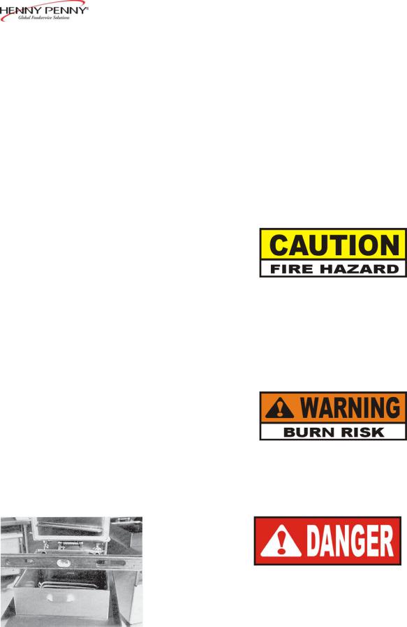
To avoid a fire, install the gas fryer with minimum clearance from all combustible and noncombustible materials, 6 inches (15.24 cm) from side and 6 inches (15.24 cm) from back. If installed properly, the gas fryer is designed for operation on combustible floors and adjacent to combustible walls.
To avoid fire and ruined supplies, the area under the fryer should not be used to store supplies.
|
To prevent severe burns from splashing hot shortening, |
|
position and install fryer to prevent tipping or move- |
|
ment. Restraining ties may be used for stabilization. |
2-4. LEVELING THE FRYER |
For proper operation, level the fryer from side to side and front to |
|
back, using level on the flat areas around the frypot collar. |
FAILURE TO FOLLOW THESE LEVELING
INSTRUCTIONS CAN RESULT IN SHORTENING
OVERFLOWINGTHE FRYPOTWHICH COULD
CAUSE SERIOUS BURNS, PERSONAL INJURY,
FIRE,AND/OR PROPERTY DAMAGE.
1207 |
2-3 |

Model 500/600
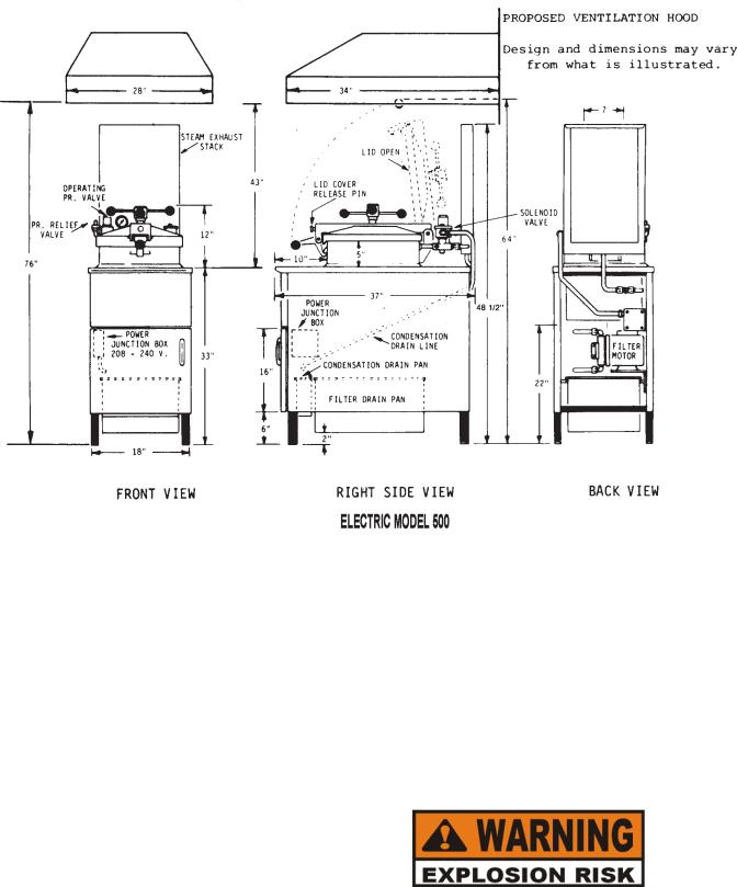
2-5. VENTILATION OF FRYER The fryer must be located with provision for venting into adequate exhaust hood or ventilation system. This is essential to permit efficient removal of the flue gases and frying odors. Special precaution must be taken in designing an exhaust canopy to avoid interference with the operation of the fryer.
We recommend you consult a local ventilation or heating company to help in designing an adequate system.
Ventilation must conform to local, state, and national codes.
Consult your local fire department or building authorities.
When installing the gas fryer do not attach an extension to the gas flue exhaust stack. This may impair proper operation of the burner, causing malfunctions and possible
negative backdraft.
2-4 |
1207 |
Model 500/600
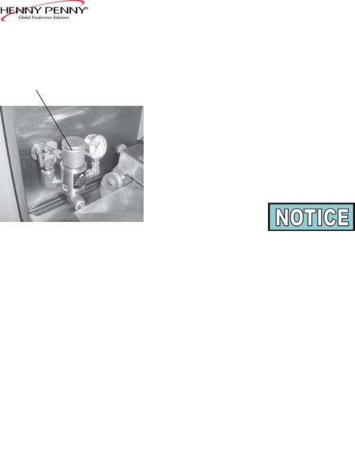
2-6. GAS SUPPLY |
The gas fryer is factory available for either natural or propane gas. |
|
Check the data plate on the right side panel of the cabinet to deter- |
|
mine the proper gas supply requirements. The minimum supply for |
|
natural gas is 7 inches water column (1.7 kPa), and 10 inches water |
|
column (2.49 kPa) for propane. Maximum gas supply is 14 inches |
|
water column (3.49 kPa, or .5 psi. |
Do not attempt to use any gas other than that specified on the data plate. Conversion kits can be installed by your distributor if required. Incorrect gas supply could cause an explosion or fire resulting in severe injuries and/or property damage.
1207 |
2-5 |
Model 500/600
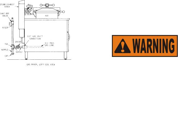
2-7. GAS PIPING |
Please refer below for the recommended hookup of the fryer to |
|
main gas line supply. |
To avoid possible serious personal injury:
•Installation must conform withAmerican National Standard Z223.1-Latest Edition National Fuel Gas Code and the local municipal building codes.
In Canada, installation must be in accordance with Standard CSA Bl49-1&2, Installation Codes Gas BurningAppliances and local codes. InAustralia, installation must conform toAustralian requirements.
•The fryer and its manual shutoff valve must be disconnected from the gas supply piping system during any pressure testing of that system at test pressures in excess of 1/2 psig (3.45 kPa)
(34.47 mbar).
•The fryer must be isolated from the gas supply piping system by closing its manual shutoff
valve during any pressure testing of the gas supply piping system at test pressures equal to or less than 1/2 psig. (3.45 kPa) (34.47 mbar).
•A standard 1/2 inch, black steel pipe and malleable fittingsshould be used for gas service connections.
•Do not use cast iron fittings.
•Although 1/2 inch size pipe is recommended, piping should be of adequate size and installed to provide a supply of gas sufficient to meet the maximum demand without undue loss of pressure between the meter and the fryer. The pressure loss in the piping system should not exceed 0.3 inch water column
(0.747 mbar).
Provisions should be made for moving the fryer for cleaning and servicing. This may be accomplished by:
1.Installing a manual gas shutoff valve and a disconnect union, or
2.Installing a heavy duty design A.G.A. certified connector which complies with the Standard for Connectors for Moveable GasAppliances,ANSI Z21.6, or CAN/CSA 6.16 with a quick disconnect coupling
2-6 |
1207 |

Model 500/600
2-7. GAS PIPING |
(Henny Penny Part No. 19921), which complies with |
(Continued) |
ANSI standard Z21.41, or CAN 1-6.9. Also adequate |
|
means must be provided to limit the movement of the |
|
fryer without depending on the connector and quick- |
|
disconnect device or its associated piping to limit the |
|
fryer movement. |
|
3. See the illustration on following page for the proper connec- |
|
tions of the flexible gas line and cable restraint. |
The cable restraint limits the distance the fryer can be pulled from the wall. For cleaning and servicing the fryer, the cable must be unsnapped from the unit and the flexible gas line disconnected. This will allow better access to all sides of the fryer. The gas line and cable restraint must be reconnected once the cleaning and servicing is complete.
1207 |
2-7 |

Model 500/600
2-7. GAS PIPING (Continued)
2-8 |
1207 |
Model 500/600
2.8 GAS LEAK TEST
Prior to turning the gas supply on, be sure the gas valve knob on the gas control valve is in the OFF position.
After the piping and fittings have been installed, check for gas leaks.A simple checking method is to turn on the gas and brush all connections with a soap solution. If bubbles occur, it indicates escaping gas. In this event, the piping connection must be redone.
To avoid fire or explosion, never use a lighted match or open flame to test for gas leaks. Ignited gas could result in severe personal injury and/or property damage.
2-9. |
GAS PRESSURE |
The gas pressure regulator on the automatic gas valve |
|
|
REGULATOR SETTING |
is factory set as follows: |
|
|
|
|
Natural: 3.5 inches water column (0.87 kPa) |
|
|
|
Propane: 10.0 inches water column (2.49 kPa) |
|
|
|
The gas pressure regulator has been set by Henny Penny and |
|
|
|
is not to be adjusted by the user. |
2-10. |
GAS PILOT & BURNER |
Lighting Procedure - Solid State Ignition |
|
|
LIGHTINGAND |
1. |
The frypot should be cleaned per the instructions in Section 3. |
|
SHUTDOWN |
2. |
The frypot must be filled to the proper level with shortening. |
|
PROCEDURE |
||
|
|
|
Refer to Filling orAdding Shortening Section. |
|
|
3. |
Turn main power switch to OFF position. |
|
|
4. |
Turn the gas valve knob counterclockwise to the OFF position. |
|
|
|
(OFF pointed down) |
|
|
5. |
Wait a sufficient length of time (at least 5 minutes) to allow any gas |
|
|
|
which may have accumulated in the burner compartment to escape |
|
Step 4 |
6. |
Turn the gas valve knob clockwise to the ON position. |
|
|
|
(ON pointed down) |
1207 |
2-9 |

Model 500/600
2-10. GAS PILOT & BURNER 7. Turn main power switch to ON position.
LIGHTINGAND
SHUTDOWN 8. Wait about 45 seconds for the burner to light.
PROCEDURE (Continued)
9.Listen for the gas burner ignition.
•It will be an audible sound due to the gas igniting at the gas jets within the burner.
10.The burner lights and operates until the shortening temperature reaches a preset temperature, and  lights.
Do not leave the burner on for more than 10 seconds without shortening in the frypot or damage to the frypot may result.
2-11. PILOT FLAME ADJUSTMENT
2-12. PRESSURE REGULATOR ADJUSTMENT (GAS ONLY)
Shutdown Procedure
1.Turn main power switch to OFF position.
2.Turn the gas valve knob counterclockwise to the OFF position.
The pilot flame is preset at the factory. If adjustment is necessary, contact your local independent Henny Penny distributor.
The gas regulator is preset at the factory at 3.5 inch water column (0.87 kPa) for natural gas (10.0 inch (2.49 kPa) for propane). If adjustment is necessary, contact your local independent Henny Penny distributor.
2-10 |
1207 |
 Loading...