

Page 1

Description for gantry axis
Position capture with motor encoder (indirect measurement)
In a gantry axis
Switch the main switch of the machine on.
Do not confirm the Power interrupted message
but immediately call the MP list.
Deactivate the position encoder for the axis concerned.
For this purpose enter the value 0 for this axis in MP 110.x.
As a precaution MP 860.x should have the value 0 for the gantry
slave axis (no compensating movement after ref erence run).
Deselect reference run for the gantry axes concerned by
entering the value 0 in MP 1340.x for each axis.
Set the limits of the traverse range for the gantry axis to
Enter the value from MP 1054.x (distance of one m otor revolution)
Enter the line count of the motor encoder of the gantry axis
concerned (visible e.g. in the diagnostics functions of iTNC 530
Increase the limits of the traverse range set by the operator to maximum
Record the currents (I noml) for the gantry axes in the integrated
oscilloscope. If the two current signals diverge distinctively, the
reason is most likely mechanical restraint of the gantry axes (non-
parallelism). In this event consult your machine tool builder, as to
whether you may move the gantry axes under this condition
(different current signals, non-parallelism of the gantry axes)!
maximum (MP 910.x to MP 922.x)
in MP 331.x of the axis concerned.
or in the motor table) in MP 332.x.
Exit the MP list and switch the machine on.
(MOD key -> TRAVERSE RANGE soft key)
Move the axis carefully!
Display of error messages
such as synchronism monitoring,
movement monitoring,
standstill monitoring?
No
Now you can traverse carefull with indirect measurement!
Yes
Press and hold
EMERGENCY
STOP and invert
MP 210.x for the
axis concerned.
17 – 300 HEIDENHAIN Service Manual iTNC 530
Page 2

18 Referencing
18.1 Definition
The position value (the coordinates) of an axis position is defined with respect to a freely
selectable datum. When the axes are moved, the ACTUAL position is calculated incrementally.
If there is an interruption in power, the reference between the axis position and the position
value is lost.
Reference marks HEIDENHAIN linear encoders are designed with one or more reference marks. The reference
marks identify an axis position at a known distance from the machine datum. The position of the
freely selectable datum is defined with respect to the machine datum.
The datum and the actual position can be reproduced as soon as the reference marks are
traversed.
+Z
Workpiece
datum
0
Machine table
Measuring system
REF Value
–44.985
10 20 30 40
Workpiece
REF Value
0
+X
Reference mark
Machine datum
Machine
datum
Distance between the scale reference point and the machine datum
Spindle preset A corresponding angle encoder or also the motor encoder in the spindle motor may be used for
The machine datum is determined by the machine manufacturer.
It is required for:
Defining the limits of traverse (software limit switches)
Moving to machine-referenced positions (such as tool change positions)
Setting the workpiece datum
For distance-coded reference marks, the machine datum is defined with respect to the scale
reference point, which is at the first reference mark after the beginning of the measuring length.
MP 960.x contains the distance between scale reference point and machine datum
.
Note
After removing and remounting a measuring system MP 960.x may have to be altered.
See “Re-Setting the Machine Datum” on page 17 – 284.
spindle orientation.
MP 3430.x contains the deviation of the reference mark from the desired position.
Note
After exchanging the angle encoder or the motor encoder in the spindle motor, it might be
necessary to set MP 3430 again.
See “Resetting the Spindle Orientation” on page 17 – 293.
May 2006 18 – 301
Page 3

18.2 Traversing the Reference Marks
The reference marks must be traversed after any interruption in power: This can be done in two
different ways:
Press the NC-START key. --> The reference marks are traversed automatically.
(the sequence of axes and how often the NC-START key must be pressed was determined by
the machine manufacturer).
or:
Press the machine axis-direction button. --> The user determines the sequence for the
referencing of the axes.
DANGER
When servicing, the machine may be in a position where the sequence for the automatic
referencing of axes could result in a collision and thus a damage or injury to the machine or
persons (e.g., error message with reboot).
Determine the sequence for the reference run yourself!
Please ensure that the last set Tilt working plane function active orinactive has been
called correctly.
Enter a low feed rate and press the corresponding axis direction keys in succession!
If necessary, ask the machine operator!
Soft key PASS OVER REFERENCE MARK
External reference pulse
If after power on of the machine no or not all reference marks were traversed (e.g., due to a
previous change to another operating mode) with PASS OVER REFERENCE MARK the
reference mark traverse must be activated. Select the manual operating mode and press the
soft key.
--> Traverse reference points appears on the screen.
After the reference marks have been traversed:
The software limit switches are activated.
The most recently saved datum and machine datum are reproduced.
PLC positioning and positioning with M91 and M92 become possible.
The counter is set to zero for axes in an open loop.
If the reference mark of the encoder cannot be used, e.g. owing to an unfavorable transmission
of motor and rotary axis, an external reference pulse may be evaluated.
In MP 4130.x a fast PLC input is defined for an external reference pulse.
In MP 1360.x the number of the fast PLC input is entered for the axis concerned.
MP 1350.x = 6 for the axis concerned.
18 – 302 HEIDENHAIN Service Manual iTNC 530
Page 4

Reference end position
To prevent the axes from violating their traverse limits when traversing the reference marks,
each axis requires a trip dog (at the reference end position). The trip dogs must be installed by
the machine tool builder at the ends of the traverse range. The switch signals from the trip dogs
are sent to free PLC inputs. The PLC program must gate these PLC inputs with W1054 for
“reference end position.”
The axis will automatically be positioned to the software limit switch if …
It is beyond the positive software limit switch and is moving in the positive direction to the
positive trip dog.
It is beyond the negative software limit switch and is moving in the negative direction to the
negative trip dog.
Encoders with EnDat interface
Double reference run
Encoders with EnDat interface can be connected to the position and speed inputs of the MC 422
(B) and CC 42x. With these encoders there is no need to traverse the reference marks. The
position value is only read when the control is switched on. It cannot be read again.
When connecting a position encoder with an EnDat interface:
MP1350.x = 5 for the axis concerned
When connecting a speed encoder with an EnDat interface:
The iTNC automatically attempts to communicate with the encoder.
When connecting a speed encoder with an EnDat interface as a position encoder:
MP1350.x = 5 for the axis concerned
MP110.x = 0 for the axis concerned
Note
If use of multiturn encoders with EnDat interfaces results in overruns, the corresponding
information is entered in the system file NCDATA.SYS. For a control exchange, this file must
be transferred or MP960.x must be readjusted (see “Exchange of HEIDENHAIN
Components” on page 26 – 411)!
During the double reference run, the absolute position is first output via the EnDat interface of
the speed encoder. If at a later time the reference mark of the position encoder is traversed, the
control continues to work with this reference.
Set the corresponding bits in MP1355 to 1 for the axes for which the double reference run is
to be used.
The distance between the speed encoder and the position encoder is entered in MP1356.x.
If the reference mark of the position encoder is first traversed, the message Set MP1356.<axis
number> to <value> appears.
Enter this value in MP1356.x.
Possible causes of error
The causes of error of encoders also apply here
--> see “Possible Causes of Error” on page 17 – 280 and
see “Possible Causes of Error” on page 17 – 287.
Especially for the referencing, the following causes of error are possible:
Defective trip dog (reference end position)
Shifted magnetic sheet (wrong or no reference mark is evaluated)
Trip dogs are too close to the reference mark signal (during reference run via the motor
encoder, a wrong reference position is evaluated)
May 2006 18 – 303
Page 5

Machine parameters
MP960.x Machine datum
Input: –1.79769313486E+308 to
+1.79769313486E+308 [mm] or [°]
Values with respect to the scale reference point
MP1320 Direction for traversing the reference marks
Format: %xxxxxxxxxxxxxx
Input: Bits 0 to 13 represent axes 1 to 14
0: Positive
1: Negative
MP1330.x Velocity for traversing the reference marks
Input: 80 to 300 000 [mm/min]
MP1331.x Velocity for leaving the reference mark end position for axes 1 to 9
(only for rotary encoders MP1350 = 2)
Input: 10 to 300 000 [mm/min]
MP1340.x Sequence for traversing the reference marks
Input: 0: No evaluation of reference marks
1 to 14: Axes 1 to 14
MP1350.x Sequence for finding the reference mark
Input: 0: Linear encoder with distance-coded reference marks (old routine)
1: Position encoder with one reference mark
2: Special type (length measurement with ROD)
3: Linear encoder with distance-coded reference marks (new routine)
4: Same as 3 except that two reference marks are evaluated
5: Encoder with EnDat interface
6: Reference pulse via fast PLC input
MP1355 Double reference run
Format: %xxxxxxxxxxxxxx
Input: Bits 0 to 13 represent axes 1 to 14
0: Reference run as defined in MP1350.x
1: Double reference run
MP1356.x Distance between speed and position encoder for double reference run
Input: –99 999.999 to +99 999.999 [mm] or [°]
MP1357.x W1032 for double reference run
Input: 0: Reset W1032 if the reference run has been over the EnDat interface of the
speed encoder
1: Reset W1032 if the reference mark was traversed with the position encoder
MP1360.x Fast PLC input for reference pulse
Input: 0: No fast PLC input for reference pulse
1 to 5: Fast PLC input for reference pulse (MP4130.x)
MP1360.x Fast PLC input for reference pulse
Input: 0: No fast PLC input for reference pulse
1 to 5: Fast PLC input for reference pulse (MP4130.x)
18 – 304 HEIDENHAIN Service Manual iTNC 530
Page 6

Position encoder
with distancecoded reference
marks
Function when MP1350.x = 3
Closed
Open
Traverse direction MP1320
Reference marks
Trip dog
"Reference end position"
May 2006 18 – 305
Page 7

Function when MP1350.x = 0. This setting is used only to ensure compatibility. Do not use for
new installations.
Reference marks
Trip dog
Closed
Open
Traverse direction MP1320
Press external START key
"Reference end position"
No Yes
Traverse direction from
MP 1320
Trip dog
"Reference end position"
closed?
Pass over two consecutive
reference marks
Is the machine
outside the software
limit switch range?
No
Invert traverse direction
from MP1320
Yes
Machine moves to
software limit switch range
Machine stops
If during automatic referencing the trip dog is not closed until it is in the reference end position
range, the contouring control will ignore this signal. It is therefore necessary that there are at
least two reference marks in the range of the reference end position.
18 – 306 HEIDENHAIN Service Manual iTNC 530
Page 8

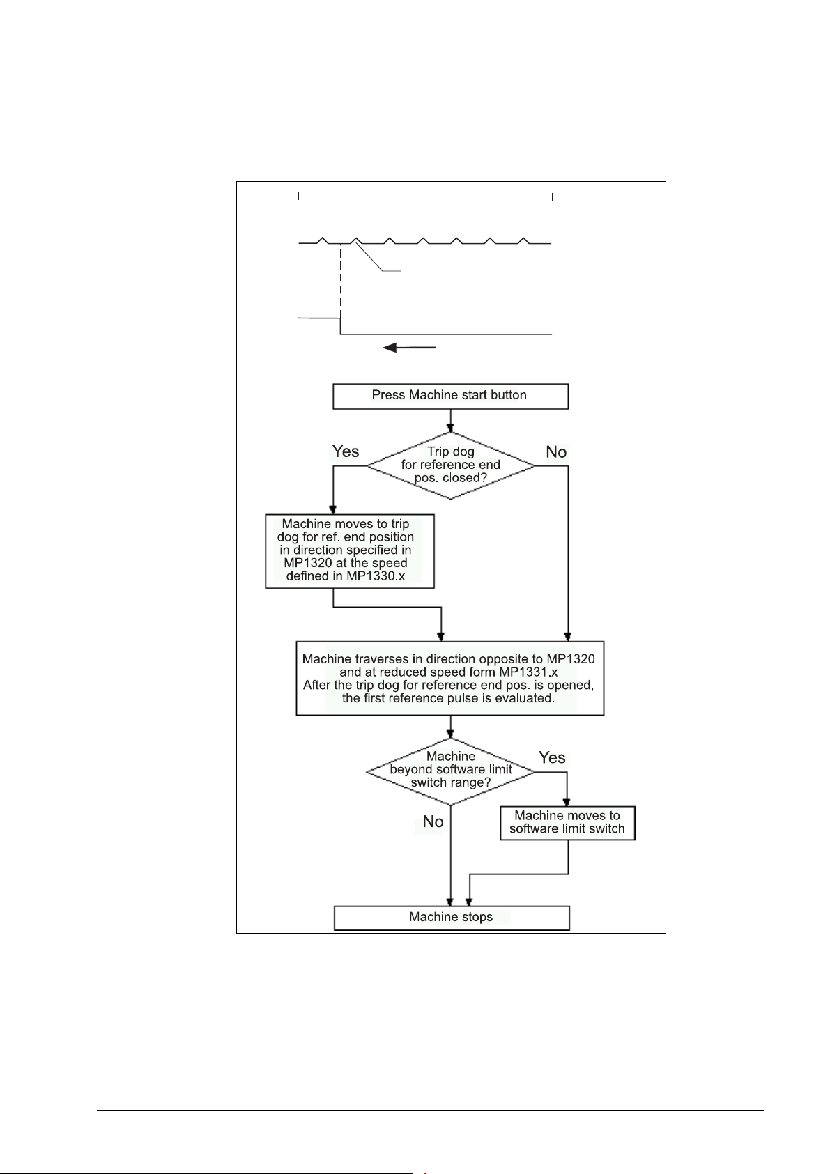
Position encoder with one reference mark
Function when MP1350.x = 1
Reference marks
Closed
Open
Traverse direction MP1320
Press the external START key
No Yes
Trip dog
"Reference end position"
closed?
Machine traverse in direction from
MP1320 with velocity from
MP1330.x to the trip dog
"Reference end positon"
Machine traverse in inverted direction
from MP1320 and with reduced velocity from MP1331.x
The first reference pulse after opening of the trip dog
"Reference end position" is evaluated
Trip dog
"Reference end position"
Is the
machine outside
the software limit
switch range?
No
Machine stops
Ye s
Machine moves to
software limit switch
May 2006 18 – 307
Page 9
Linear measurement through rotary encoder
Function when MP1350.x = 2
For linear measurement using a rotary encoder, a reference pulse is produced at each revolution
of the encoder. Ensure that during referencing the same reference pulse is always evaluated.
This can be realized with the trip dog for reference end position.
Measuring length
Reference pulse
Desired reference pulse
Closed
Open
Traverse direction MP1320
Trip dog
"Reference end position"
18 – 308 HEIDENHAIN Service Manual iTNC 530
Page 10

18.3 Deselect Referencing for Axes
For axis examinations it is possible to deselect the referencing MP 1340.x.
Enter value 0 (= no evaluation of the reference mark) for the corresponding axis.
Note
In MP1340.x the sequence for the reference mark run is listed.
With following entries, i.e.:
MP1340.0 : 3
MP1340.1 : 2
MP1340.2 : 1
... first the 3rd axis is referenced (e.g., Z axis), then the 2nd axis (e.g., Y axis) and
subsequently the 1st axis (e.g., X axis).
If you now want to deselect the X axis, you must enter MP1340.2 = 0!
May 2006 18 – 309
Page 11

18 – 310 HEIDENHAIN Service Manual iTNC 530
Page 12

19 Checking the Enables on the iTNC
19.1 General
With an operating axis (axis in control) ...
No terminal symbol is shown
The "STIB" star (control in operation) is shown.
The feed rate enable must not be highlighted.
The position display changes in case of a movement.
READY
symbol
Clamping
symbol
Position display
Feed rate
display
To operate with axes or spindles the appropriate enables are required.
If one or several enables are missing, an error message is output or the axes and/or the spindles
cannot be operated.
The following conditions must be fulfilled to drive digital axes and spindles:
I3 set
(X42/4, Control-is-ready signal acknowledgement)
I32 set
(X42/33, global drive enabling; the functionality of the I 32 global drive enabling is defined in
MP 2050.
24V at X150 / 151 for the corresponding axis group is available.
(X150/151 are not wired on every machine,
but if they are, you can see in MP 2040, how the axis groups are assigned)
May 2006 19 – 311
Page 13

Drives ready for operation
(on the HEIDENHAIN inverter system the green LEDs READY at the drive modules UM xxx
or at the output stages of a compact inverter) must be lit.
Note
If a drive is taken in control, there must be a READY signal from the drive module after a
defined time. For this purpose the corresponding relays must trigger.
The iTNC monitors the time between power on of the control and the READY signal of the
drive modules via the PWM cables.
If the READY signal is missing after the waiting time has passed, the error message
8B40 No drive release <axis>appears.
E.g., a connection may be interrupted, or the relays trigger too slowly or the drive is
defective, etc.
The permissible waiting time is entered in MP2170.
It is possible that this error message is not generated as the PLC program does not hook up
the current and speed controllers as long as the ready signal of the drives is missing. -->
Observe the green READY-LEDs of the drives. --> See “Checking the Readiness of the
Inverter System” on page 19 – 322
PLC module 9161 called
(This module serves to activate the current and speed controllers individually for each axis.
If necessary ask the machine manufacturer, in which program part this module is called.)
Note
The word W1024 contains the axes enabled by the NC.
The word W1060 contains the axes for which the feed rate was individually enabled by
the PLC.
If the marker M4563 is set, the PLC enables the feed rate in all axes.
(Use either W1060 or M4563.)
The word W1040 contains the axes in which the control loop is opened by the PLC
(e.g., with. clamping axes).
The PLC module 9169 serves to call those axes for which I32 does not switch off the drives.
MP2040 Axis groups for drive enabling through X150 / X151
Format: %xxxxxxxxxxxxxx
Input: 0: Axis not assigned
1: Axis assigned
MP2040.0-5: Groups 1 to 6
MP2040.6-7: Reserved, enter %00000000000000
MP2050 Functionality of drive enabling I32 (X42/33)
Input: 0: Emergency stop for all axes, Module 9169 not effective
1: Emergency stop for all axes that are not excepted with Module 9169
2: I32 and Module 9169 are without functionality
MP2170 Waiting time between the switch-on of the drive and the drive’s standby
signal
Input: 0.001 to 4.999 [s]
0: 2 [s]
19 – 312 HEIDENHAIN Service Manual iTNC 530
Page 14

19.2 Examination
The iTNC 530 features comprehensive diagnosis possibilities.
--> See “Integrated Diagnosis Functions” on page 7 – 41.
These diagnosis functions can be used for the following examinations!
Selection of the supply device
Select the power supply unit used
(not all status information of non-HEIDENHAIN inverters can mostly be used):
May 2006 19 – 313
Page 15

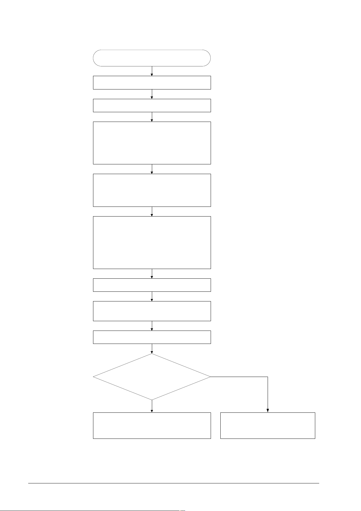
19.2.1 Examination of the Output Control-is-ready (X41/pin34) and Input Control-is-ready signal acknowledgement I3 (X42/pin 4)
If the message Relay external DC voltage missing does not disappear after pressing the key
Control ON, carry out the folllowing fault diagnosis:
“Control is Ready“ check
Switch control on as far as possible.
Check status of the Acknowledgment: Control
is Ready (-NE1) indicator in the Drive
diagnosis window (or check in the
PLC TABLE, whether I3 is set.)
Acknowledgment present
(green indicator or
I3 = 1)?
No
+ 24 V present at input
Acknowledgment: Control is Ready
(X42/PIN4)?
No
EMERGENCY STOP chain
(EMERG. STOP button, axis limit
switches, etc.) interrupted?
No
+24 V present at output
Control is Ready
(X41/PIN34)?
Yes
Yes
Yes
Yes
The control records the
acknowledgment. The message
Relay external DC voltage missing
should disappear. If it does not,
please call HEIDENHAIN!
The PLC does not detect the
high level. Probably the input I3
on the MC is defective.
-> Replace the MC!
Remove the interruption.
There is still an interruption which
needs to be removed. (Use the circuit
diagram of the machine.)
No
Supply voltage present for
output Control is Ready (connector
X34/PIN1 = 24V, PIN2 = 0V)?
No
Find the reason and correct the error.
(Make use of the circuit di agram of the machine.)
Yes
The Control is Ready output of the
MC is probably defective.
-> Replace the MC!
19 – 314 HEIDENHAIN Service Manual iTNC 530
Page 16

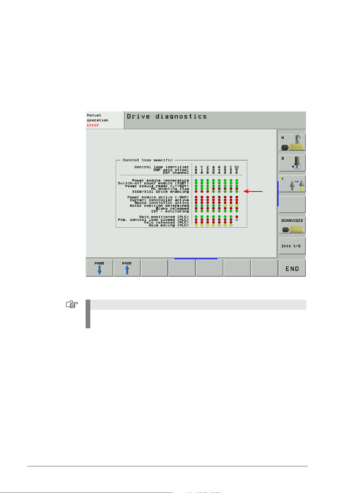
Page from the DSP diagnosis of drives
Call via the soft keys DIAGNOSIS --> DRIVE DIAGNOSIS --> DSP
See “Integrated Diagnosis Functions” on page 7 – 41.
Excerpt from the basic circuit diagram
Here you can see the terminals that can be measured
(the PLC inputs and outputs are mostly connected to a strip in the electrical cabinet).
May 2006 19 – 315
Page 17

Sliding switch on I/O module
Note
If the Control-is-ready output on the MC is defective, you can use the Control-is-ready
output of a PLC expansion board as makeshift:
PL 405 B or PL 410 B: X8 / pin16
PL 510, input/output module PLD 16-8: X6 / terminal 8
(The function of this terminal can be set with a sliding switch on the rear side of the
corresponding I/O modules, setting 1 = "Control is ready", See “X6: PLC outputs on the PL
510” on page 13 – 197)
19 – 316 HEIDENHAIN Service Manual iTNC 530
Page 18

Error message
EMERGENCY STOP
DEFECTIVE
If the error message "Emergency Stop Defective" appears when the machine is switched on,
carry out the error diagnosis as follows:
Error message EMERGENCY STOP Defective
The machine is switched on.
Is the input I3
(X42/PIN4) permanently
on high level?
No
Switch the main switch of the machine off.
Disconnect and secure the original wires.
Insert a bridge between X41/PIN34 and X42 /PIN4
(output and input of Control is Ready).
Observe that the potent ia l of the power supply is the
same -> See „“Caution“ box below this chart.
Switch the main switch of the machine on.
Does the error message
EMERGENCY STOP Defective
reappear?
Yes
Yes
Find the reason and correct
the error. (Make use of
the circuit diagram
of the machine.)
The MC is probably
defective.
-> Replace the MC.
No
The fall time of the relay triggered by the output X41/
PIN34 is probably too long.
-> Replace the relay.
Caution
If 24 V is supplied to the control-is-ready output from the HEIDENHAIN inverter system via
connector X34, potential differences between the 24 V machine voltage and the 24 V from
the inverter can result in compensating currents.
Therefore it is perferable to supply X34 with machine voltage before you insert a bridge
between the "Control-is-ready" input and output during the following investigation!
May 2006 19 – 317
Page 19

Bridge inserted
Acknowledgment:
Control is Ready
I3
Control is Ready
Note
The function of the Control-is-ready output of an I/O module PLD 16-8 can also be tested
with this method.
Note
Course of the emergeny stop (or booting) routine.
--> See “Monitoring Functions” on page 9 – 55!
19 – 318 HEIDENHAIN Service Manual iTNC 530
Page 20

19.2.2 Checking the Global Drive Enable I32, Connector X42 / pin 33
If you can switch on the machine but cannot move with a digital axis/spindle, check the
following:
Checking I32
Switch the control on as far as possible.
Check the status of the
Drive enabling (-NE2) in the
Drive diagnostics window
(or check in the PLC TABLE, whether
I32 is set).
Yes
Acknowledgment present
(green indicator or
I32 = 1) ?
No
Yes
The control records the
acknowledgment! If, however, you
still cannot operate the digital
axes/spindle, please call your
machine tool builder or HEIDENHAIN!
No
Is an
NC-STOP signal pending?
(marker 4560 = 0)?
Yes
Find the reason (e.g. break between
NC-STOP button an d control or
stuck NC-STOP button) and
correct the error.
+ 24 V available at X42/PIN33 ?
No
The conditions for drive enabling
are not fulfilled (door contacts,
permissive keys etc.)
Use the circuit diagram of the machine
to check the contacts, relays, wiring, etc.
The PLC does not detect the high
level. Probably the input I3 2 on the
MC is defective. -> Replace the MC!
May 2006 19 – 319
Page 21

Page from the DSP diagnosis of drives
Call via the soft keys DIAGNOSIS --> DRIVE DIAGNOSIS --> DSP
See “Integrated Diagnosis Functions” on page 7 – 41.
Excerpt from the basic circuit diagram
Here you can see the terminals that can be measured
(the PLC inputs and outputs are mostly connected to a strip in the electrical cabinet).
Drive enabling
for all axes
I32
Drive enabling
for axis groups
Do not connect,
If MP2040 = 0
19 – 320 HEIDENHAIN Service Manual iTNC 530
Page 22
19.2.3 Checking the Drive Enabling for the Axis Groups via Connector X150 and X151 (if Wired)
Check whether 24V are available for the axis group to be traversed.
The axis groups for the drive enabling via X150 (main DCB) and X151 (auxiliary DCB) are
defined in MP2040.
Check according to the integrated drive diagnosis whether the corresponding axis groups are
released:
Note
If no axis groups are defined in MP 2040, the default setting of the drive release is active
(via X150 / X151).
May 2006 19 – 321
Page 23

19.2.4 Checking the Readiness of the Inverter System
Selection of the power supply unit
Select the power supply unit used for the integral diagnosis functions
(mostly not all status information of non-HEIDENHAIN inverters can be used):
Green “READY” LED on
Check according to the integrated drive diagnosis whether the corresponding axis groups are
released:
19 – 322 HEIDENHAIN Service Manual iTNC 530
Page 24

Check according to the integrated drive diagnosis whether the power modules are ready:
Open the electrical cabinet and also check whether the green READY-LEDs on the compact
inverter or the power supply unit light up (a non-HEIDENHAIN inverter is probably also
equipped with a corresponding LED or display).
Inverters LED
UE 1xx, UE 2xx B compact inverter READY
UE 2xx compact inverter AXIS/SPINDLE READY
UR 2xx, UR 2xxD compact inverter READY UV
UV 120, UV 140, UV 150, UV 1xx D,
UVR 1xx,
READY UV and
POWER MODULE READY
UVR 1xx D power supply unit
UV 130D power supply unit READY
UV 130 D power supply unit READY UV
Check if the green READY-LED lights up on, e.g.
on the compact inverter
on the UM axis module
on the HEIDENHAIN interface board for the SIMODRIVE system
for the axis to be traversed.
(A non-HEIDENHAIN inverter is probably also equipped with a corresponding LED or display.)
May 2006 19 – 323
Page 25

If the READY LEDs are not lit, proceed as follows:
Check the supply of the inverter system.
Check the electrical cabinet (relays, wiring, etc.).
Check the ribbon cables and the plug-type connectors at the inverter system.
Note
Use the circuit diagram of the machine tool for this purpose.
Further inspection routines --> see service manual for Inverter Systems and Motors!
Red LED SH1 The SH1 signal (safe stop 1) indicated by a red LED at the inverter, is generated by the computer
of the iTNC. The signal is low-active, i.e. line-break proof.
If the computer is not ready for operation or if an error is pending, SH1 is output. The red SH1
LED and the green READY LED at the inverter can never be lit a the same time. They are
mutually locked.
Red LED SH2 The SH2 signal (safe stop 2) indicated by a red LED at the inverter, is generated by the controller
of the iTNC. The signal is low-active, i.e. line-break proof.
If an axis or spindle is not controlled, SH2 is pending and the red LED is on.
This is for example the case with clamped axes or if a spindle is not controlled.
SH2 and READY are on simultaneously.
Note
HEIDENHAIN interface cards for the SIMODRIVE system:
The cards for the plug-type connectors (ribbon cables) are equipped with the green READY
LED and the red LEDs SH1 and SH2.
The cards with D-Sub connectors are equipped with the green READY LED and the red
LEDs RESET X1 und RESET X2 for the respective axis.
RESET X1, RESET X2 correspond to the SH2 signal.
The first generation of the cards with D-Sub connectors feature a green IF LED and a red
NB LED.
IF stands for "pulse enable" (German: Impulsfreigabe) and means that the axis module is
ready.
NB means that the axis module is "not ready" (nicht bereit).
For further information on the drives please refer to the service manual "Inverter Systems
and Motors".
19 – 324 HEIDENHAIN Service Manual iTNC 530
Page 26

19.2.5 Checking PLC Modules, Markers and Words
For the following investigations, the PLC diagnosis functions are used.
--> See “PLC Diagnosis” on page 10 – 73.
For these PLC analyses it might be helpful or often even necessary to contact the machine
manufacturer for support.
Check whether the PLC module 9161 is called in the corresponding PLC program.
(ask the machine manufacturer in which program block this PLC module is called).
For this purpose enter the PLC TRACE mode.
This module serves to activate the current and speed controllers individually for each axis.
Check the value in the word W1024.
For this purpose enter the PLC TABLE.
The word W1024 contains the axes enabled by the NC.
Check the value in the word W1060 or whether the marker 4563 is set.
For this purpose enter the PLC TABLE.
The word W1060 contains the axes for which the feed rate was individually enabled
by the PLC.
If the marker M4563 is set, the PLC enables the feed rate in all axes.
(Either W1060 or M4563 is used.)
Check the value in the word W1040.
For this purpose enter the PLC TABLE.
The word W1040 contains the axes in which the control loop is opened by
the PLC (e.g., clamping axes).
May 2006 19 – 325
Page 27

Note
The value of the words is displayed in hexadecimal or decimal format.The hexadecimal
format is distinguished by a leading $. A hexadecimal digit comprises 4 bits. I.e. you can,
for example, calculate for which axes the feed rate is enabled.
Example: W1024 = $004F
The first HEX digit has the value F, that is the first 4 axes are enabled
0+21+22+23
(2
The second HEX digit has the value 4, i.e. the 7th axis is enabled (22 = 4).
In the binary format this is 0100 1111 and in the decimal format this is the value 79.
= 1+2+4+8 = F).
Value of
indivdual places
Place value
considered
$ 0 0 4 F
0 1 0 0 1 1 1 1
0
23 22 21 2
23 22 21 2
0+4+0+0 8+4+2+1
4
27 26 25 2
4
15
23 22 21 2
0+64+0+0 + 8+4+2+1
79
= HEX
= BIN
0
0
= DEC
19 – 326 HEIDENHAIN Service Manual iTNC 530
Page 28

20 Interface to the Drives
20.1 Digital Drives
20.1.1 Introduction
Digital drive systems are also referred to as inverter systems.
For digital drives three-phase ac motors are used.
The most important motors are:
Synchronous motors (e.g., HEIDENHAIN axis motors)
Asynchronous motors (e.g., HEIDENHAIN spindle motors)
Linear motors
Torque motors
The digital servo amplifiers are controlled via so-called PWM interfaces (PWM = Pulse Width
Modulation).
The position, speed and current controllers are located in the HEIDENHAIN control.
Following PWM interfaces are located on the CC 422 / 424 controller unit
(every digital axis/spindle has its own PWM ribbon-cable connector):
X51 to X56
X57 to X64 (depending on the expansion stage)
Note
On the CC 424 (not CC 422), the speed encoder inputs are firmly assigned to the PWM
outputs. --> See following table!
MP 112.x for the variable assignment of the speed encoders is not available for the CC 424!
Drive control board
of CC 424
1X51X15
1X52X16
1X53X17
1X54X18
1X55X19
1X56X20
2X57X80
2X58X81
2X59X82
2X60X83
Caution
The service on the CC 424 and CC 422 is different.
Ensure to use the correct instructions!
PWM output
(MP120.x/MP121.x)
Speed encoder input
May 2006 20 – 327
Page 29

MP 100 contains the axis sequence (first, second, third axis etc.).
Caution
MP 100 must not be edited!
The allocation of PWM outputs to the axes can be found in the machine parameters
MP 120.x
Note
The connectors as of X57 can be assigned as of MP 120.6 (7th axis), but not those before!
The allocation of PWM outputs to the spindles can be found in the machine parameters
MP 121.x.
20.1.2 Possible Causes of Errors
Defective PWM interface or defective CC
Defective cable
Defective power module
Defective motor
Poor shielding and grounding
Mechanical defects
Error in the NC or PLC software
Wear and tear of mechanical parts
Deterioration of the machine
Defective HEIDENHAIN interface board for the SIMODRIVE 611 drive system
Wrong grounding in connection with the so-called HEIDENHAIN interface boards
There is wide variety of possible error causes.
Profound knowledge of the machine and the interaction of the components is very helpful for
this type of error.
If error messages are generated, press the HELP key. To obtain information on possible error
causes and tips for error elimination.
20 – 328 HEIDENHAIN Service Manual iTNC 530
Page 30

20.1.3 Trouble Shooting: Exchanging PWM Outputs on the CC 422
To find out whether the PWM interface on the control or the connected drive system is
defective, you can try another PWM interface on the control.
Use the interface of a funtioning axis!
Modular setup with CC 422
UV
UM
UM
UM
UP
UV 105
CC 422
MC 422
Example: Error in X-axis
Assumed machine parameters
PWM
PWM
For fault diagnosis, proceed as follows:
MP 100.x = - - - - -CZYX (X = 1st axis, Y = 2nd axis, Z = 3rd axis, C = 4th axis)
MP 2180.x = 0 (PWM frequency = 5 kHz for all axes)
MP 120.0 = 51 (X axis on PWM output X51)
MP 120.1 = 52 (Y axis on PWM output X52)
MP 120.2 = 53 (Z axis on PWM output X53)
MP 120.3 = 54 (C axis on PWM output X54)
MP 121.0 = 56 (1. Spindle on PWM output X56)
MP 121.1 = 0 (2. spindle not active)
Notes and preliminary actions
Exchange the PWM output a functioning axis
(depending on the configuration of the PWM frequencies, unassigned PWM outputs may not
be active)
Please observe that only within the groups X51 to X56 (main drive-control board)
and X57 to X64 (drive-control board) an exchange is possible!
The same PWM frequency should be set for axes to be exchanged!
If different PWM frequencies are entered in parameter group MP 2180.x, ask the machine
manufacturer or HEIDENHAIN for further service measures (the assignment of the machine
parameter blocks for the current or speed controller by means of MP 130.x must also be
regarded).
Before exchanging the speed encoder inputs, deactivate the evaluation of the electronic
ID labels in MP 7690!
Enter value 1 for each bit.
May 2006 20 – 329
Page 31

Block dDiagram
Note
Always exchange both, the cable and interface assignment by means of machine
parameters!
Note
It is not relevant for this test routine which drive modules are connected!
20 – 330 HEIDENHAIN Service Manual iTNC 530
Page 32

Flowchart CC 422
Interchanging the PWM outputs of CC 422
Switch off the main switch of the machine tool.
Unscrew the cover plate from the inverter system.
Interchange the PWM ribb on cables of the axes
concerned at CC 422 (in the example:
Connectors X51 and X52) .
CAUTION: Handle the ribbon cable connectors
with care! Do not bend the pins!
Screw the cover plate to the inverter system.
CAUTION: Do not damage the ribbon cable!
Switch the main switch of the mac hin e on.
Do not confirm the Power interrupted message
but immediately call the MP list and in
MP120.x interchange the entry values of
the axes concerned.
(In the example: MP 120 . 0 : 52 / MP 120.1: 51)
Confirm the Power interrupted message and
switch the control voltage on.
Traverse the axes.
Does the error pattern
move to the other axis?
(In the example from
X to Y)
Yes
The defect is probably located
in the PWM interface of CC 422.
No
The defect is probably locat ed
in the drive system (power module,
motor, cables, etc.)
Note
Set MP 7690 (evaluation of the electronic ID label) to its original state after the test!
May 2006 20 – 331
Page 33

Corrective action If you have found out that the interface on the CC 422 is defective …
Exchanging the CC. --> See “Exchange of HEIDENHAIN Components” on page 26 – 411.
If you have detected that the error is outside the control (servo amplifier, motor, cable, etc.):
Start the following routine. --> See “Trouble Shooting: Exchanging Power Modules or Output
Stages of the Same Type” on page 20 – 337
20 – 332 HEIDENHAIN Service Manual iTNC 530
Page 34

20.1.4 Trouble Shooting: Exchanging PWM Outputs on the CC 424
To find out whether the PWM interface on the control or the connected drive system is
defective, you can try another PWM interface on the control.
Use the interface of a funtioning axis!
Modular setup with CC 424
Example: Error in X-axis
Assumed machine parameters
Notes and preliminary actions
For fault diagnosis, proceed as follows:
MP 100.x = - - - - -CZYX (X = 1st axis, Y = 2nd axis, Z = 3rd axis, C = 4th axis)
MP 2180.x = 0 (PWM frequency = 5 kHz for all axes)
MP 120.0 = 51 (X-axis at motor power stage connection X51)
MP 120.1 = 52 (Y-axis at motor power stage connection X52)
MP 120.2 = 53 (Z-axis at motor power stage connection X53)
MP 120.3 = 54 (C-axis at motor power stage connection X54)
MP 121.0 = 56 (1. spindle at motor power stage connection X56)
MP 121.1 = 0 (2. spindle not active)
Exchange the PWM output a functioning axis
(depending on the configuration of so-called single-speed and double-speed outputs,
unassigned PWM outputs may not be active)
So-called single-speed and double-speed PWM outputs with equal PWM frequency can be
exchanged for test purposes.
Please observe that only within the groups X51 to X56 (main drive-control board)
and X57 to X64 (drive-control board) an exchange is possible!
The firmly assigned motor encoder output must also be exchanged!
The same PWM frequency should be set for axes to be exchanged!
If different PWM frequencies are entered in parameter group MP 2180.x, ask the machine
manufacturer or HEIDENHAIN for further service measures (the assignment of the machine
parameter blocks for the current or speed controller by means of MP 130.x must also be
regarded).
Master-slave axes function only on the outputs X51 to X53 and X52 to X54.
Before exchanging the speed encoder inputs, deactivate the evaluation of the electronic
ID labels im MP 7690!
Enter value 1 for each bit.
May 2006 20 – 333
Page 35

Block Diagram
Note
Always exchange both, the cable and interface assignment by means of machine
parameters!
Note
It is not relevant for this test routine which drive modules are connected!
20 – 334 HEIDENHAIN Service Manual iTNC 530
Page 36

Flowchart CC 424
Interchanging the PWM outputs of CC 424
Switch off the main switch of the machine tool.
Unscrew the cover plate from the inverter system.
Interchange the PWM ribbon cables of the axes
concerned at CC 424
(in the example: Connectors X51 and X52).
CAUTION: Handle the ribbon cable connectors
with care! Do not bend the pins!
Connect the motor encoder cables to the correct
PWM outputs of the CC 424
(in the example: Connectors X15 and X16).
See assignment in the introduction to this chapter.
Screw the cover plate to the inverter system.
CAUTION: Do not damage the ribbon cable!
Switch the main switch of the machine on.
Do not confirm the Power interrupted message but
immediately call the MP list and in MP 120.x
interchange the entry values of the axes concerned.
(In the example: MP 120.0: 52 and MP 120.1: 51)
Confirm the Power interrupted message and switch
the control voltage on.
Traverse the axes.
Does the error pattern
move to the other axis?
(In the example from
X to Y)
Yes
No
The defect is probably located in
the drive system (power module,
motor, cables, etc.)
The defect is probably loca ted
in the PWM interface of CC 424.
Note
Set MP 7690 (evaluation of the electronic ID label) to its original state after the test!
May 2006 20 – 335
Page 37

Corrective action If you have found out that the interface on the CC 424 is defective …
Exchanging the CC --> See “Exchange of HEIDENHAIN Components” on page 26 – 411.
If you have detected that the error is outside the control (servo amplifier, motor, cable, etc.):
Start the following routine. --> See “Trouble Shooting: Exchanging Power Modules or Output
Stages of the Same Type” on page 20 – 337
20 – 336 HEIDENHAIN Service Manual iTNC 530
Page 38

20.1.5 Trouble Shooting: Exchanging Power Modules or Output Stages of the Same Type
General If you have found out that the PWM interface on the CC is in order, you can test if a traverse of
the faulty axis with …
a dimensionally identical power module (modular inverter system) or
an output stage with equal power (2-axis-module, compact inverter)
is possible.
DANGER
If you want to use other types of power stages or output stages, we strongly recommend
contacting your machine manufacturer or HEIDENHAIN. Otherwise you could cause
damage or injury to machine or persons!
Use one of the following units:
Either a replacement unit
Or a power stage or output stage already located in the electrical cabinet but is not used (with
compact inverters, e.g., a output stage with equal power could be available)
Or the power stage or output stage of a functioning axis
Note
It is not necessary to exchange a machine parameter for this test routine!
It does not matter whether the power stages are from HEIDENHAIN or other
manufacturers.
Caution
If you strongly suspect that the motor of the axis to be examined causes a short circuit
(penetration of humidity, etc.), you must not connect it to another power stage as it could
be destroyed!
DANGER
Always secure vertical axes from falling down before you perform this test!
DANGER
Danger of electrical shock!
Make sure that the main switch of the machine is switched off and that any connectors and
terminals are free of potential before you engage or disengage them.
May 2006 20 – 337
Page 39

Assumed configuration for two 1-axis modules
UM 12x: X111 (PWM connection of channel 1) connected with X51 (iTNC, X axis)
X81 (motor connection of channeel 1) connected with motor X axis
UM 11x: X111 (PWM connection of channel 1) connected with X52 (iTNC, Y axis)
X81 (motor connection of channel 1) connected with motor Y axis
Assumed configuration for one 2-axis module
Example: Error in X axis
Block diagram for two 1-axis modules
UM 12x: X111 (PWM connection of channel 1) connected with X51 (iTNC, X axis)
X112 (PWM connection of channel 1) connected with X52 (iTNC, Y axis)
X81 (motor connection of channel 1) connected with motor X axis
X82 (motor connection of channel 2) connected with Y-axis
For fault diagnosis, proceed as follows:
Caution
If motor brakes are connected to the power stages, they have also to be exchanged (X344,
X392, X393, X394, depending on the model. --> see Service Manual for Inverter Systems
and Motors)!
Motor brakes can be connected to current HEIDENHAIN inverter modules and compact
inverters. The motor brake is also powered via a connector on the inverter. The trigger
signals for the motor brakes are transmitted via the PWM bus.
20 – 338 HEIDENHAIN Service Manual iTNC 530
Page 40
Flowchart for two 1-axis modules
Interchanging power modules of the same type
Switch off the main switch of the machine tool.
Unscrew the cover plate from the inverter system.
Interchange the PWM ribb on cables of the axes
concerned at the power modu les or output
stages (in the example: connectors X111).
CAUTION: Handle the ribbon cable connectors
with care! Do not bend the pins!
Screw the cover plate to the inverter system.
CAUTION: Do not damage the ribbon cable!
Connect the motor connec tors to the
power module or to the compact inverter
in accordance with the PWM inputs
(in the example: connectors X81).
CAUTION: If motor brakes are to be controlled
by the power module, their connections has
to be altered as well!
Switch the main switch of the mac hin e on.
Confirm the Power interrupted message and
switch the control voltage on.
Traverse the axes.
Does the error pattern
move to the other axis
(in the example from
X to Y)?
No
Yes
The defect is probably located
in the power module / output stage.
The defect is probably due to the
motor, the motor cable, the PWM
ribbon cable or the mechanics.
May 2006 20 – 339
Page 41

20.1.6 Trouble Shooting: Exchanging the HEIDENHAIN Interface Boards for the SIMODRIVE 611 System
If a SIMODRIVE 611 system is used in connection with the HEIDENHAIN control, there are
HEIDENHAIN interface boards in the Siemens drive modules to adapt the PWM signals.
Boards of the same type
Boards of different types
Before using other drive modules for examination of faulty axes, you may exchange
dimensionally identical expansion boards.
Observe the following:
The machine is not under power when you exchange the boards
Boards of the same type are exchanged (1-axis module or 2-axis module, metallically isolated
or not metallically isolated --> See “Important Notes on the Use of HEIDENHAIN Interface
Boards in SIMODRIVE System” on page 5 – 29)
The grounding is correct --> See “Important Notes on the Use of HEIDENHAIN Interface
Boards in SIMODRIVE System” on page 5 – 29
If you do not have boards of the same type, under certain circumstances you may exchange
boards for 1-axis modules for boards for 2-axis modules and vice versa.
Difficulties can be:
Some 2-axis module boards (ID number smaller than 359002-xx) require the corresponding
enabling signals of the control on every PWM interface. If such a board is inserted in a 1-axis
module and one PWM interface is not assigned, the complete board is not released.
If a 1-axis module board is inserted in a 2-axis module for test purposed, the corresponding
axis can be inspected (if the other axis is to be inspected, to motor output on the power stage
must be reconnected).
For these tests it might be necessary to deselect axes that cannot be contolled by MP 10.
With some machines this might be difficult.
--> If necessary, ask the HEIDENHAIN service agency!
Caution
Boards with metallic isolation of HEIDENHAIN PWM signals to the Siemens interface must
not be replaced by boards without metallic isolation and vice versa!
--> See “Important Notes on the Use of HEIDENHAIN Interface Boards in SIMODRIVE
System” on page 5 – 29
20 – 340 HEIDENHAIN Service Manual iTNC 530
Page 42

20.2 Analog Drives
20.2.1 Introduction
Analog servo amplifiers ars also referred to as analog servos.
For analog drives often DC motors are used.
The analog servo amplifiers are controlled via ±10V interfaces.
The position controller is located in the MC, speed and current controller in the servo amplifier.
The HEIDENHAIN control also supplies the nominal speed value. This is why the ± 10V interface
is also designated as nominal speed value interface.
On the MC 42x (B) there are the following analog nominal speed value outputs:
X8 and X9
On each of these D-Sub connectors there are several analog channels.
MP 100 contains the axis sequence (first, second, third axis etc.).
Caution
MP 100 must not be edited!
The allocation of nominal speed value outputs to the axes can be found in the machine
parameters.
MP 120.x
The allocation of nominal speed value outputs to the spindles can be found in the machine
parameters.
MP 121.x
20.2.2 Possible Causes of Errors
Defective nominal speed value interface of the MC (X8, X9)
Defective cable
Defective servo amplifier
Defective motor (carbon brushes, tachometer brushes, winding, etc.)
Poor shielding and grounding
Mechanical defects
Errors in the NC or PLC software
Wear and tear of mechanical parts
Deterioration of the machine
There is wide variety of possible error causes.
Profound knowledge of the machine and the interaction of the components is very helpful for
this type of error.
If error messages are generated, press the HELP key. To obtain information on possible error
causes and tips for error elimination.
20.2.3 Testing the Analog Nominal Speed Value Interface
The control outputs an analog voltage of 0 V to maximum ± 10 V (the analog voltage is entered
in MP 1050.x).
This voltage can be measured at the connecting terminals of the servo amplifier or directly at the
MC with the HEIDENHAIN test adapter.
May 2006 20 – 341
Page 43

Investigation with the integrated oscilloscope
With the integrated oscilloscope the Volt. analog voltage can observed:
Error: No axis traverse!
See “Integrated Oscilloscope” on page 8 – 49.
It is a prerequisite that the release conditions (e.g., door contacts, permissive buttons, etc.)
for the axis movements are given.
For the axes to be traversed ...
No terminal symbol before the axis concerned must be shown.
The feed rate display (F …) must not be highlighted.
The "STIB" star (control in operation) must be shown.
If necessary, ask the machine operator!
20 – 342 HEIDENHAIN Service Manual iTNC 530
Page 44

Flowchart If nevertheless one or several analog axes do not function, you may investigate the following:
Analog axis does not move
Switch the machine off and connect a multimeter
to the terminal strip of the servo amplifier of the
(Use the circuit diagram of the machine.)
Switch off the main switch of the machine.
Do not confirm the Power interrupted message but
immediately call the MP list and increase the tolerances
for movement and following-err or monitoring in the axis
to be checked:
(Note down the original values and restore them later.)
axis to be checked.
MP 1140.x : 9.99 [V]
MP 1410.x : 30 [mm]
MP 1420.x : 30 [mm]
MP 1710.x : 300 [mm]
MP 1720.x : 300 [mm]
Switch the machine on and
set the position display to LAG.
Turn the feed-rate potentiometer to zero
and start reference run for the defective axis
(e.g. with axis direction button).
Slowly turn up the feed-rate potentiometer
and observe the display of the multimeter.
Yes
Does the mulitmeter read a
voltage in the range of +/- 10 V?
No
Switch the machine off and disconnect the analog
servo amplifier from the speed command cable.
Repeat the above procedure with the servo a mplifier
disconnected.
Yes
Does the mulitmeter read a
voltage in the range of +/- 10 V?
The MC operates correctly;
the defect is probably due to the
analog servo amplifier and its
cables, to the motor etc.
No
MC or speed command cable defective.
May 2006 20 – 343
Page 45

Note
If the control functions properly, a nominal speed value interface can be read in the above
routine until the monitoring value (movement, servo lag, etc.) is reached. The nominal speed
value voltage 0 V is output together with the corresponding error messages.
Battery box If available, you can investigate whether the analog servo amplifier can be operated with a
"Battery box" (not a HEIDENHAIN unit).
This battery box replaces the control and provides the analog servo amplifier with a nominal
speed value of ± 10 V.
(The servo amplifier must be released. --> If necessary, ask the machine manufacturer!)
Measuring setup with test adapter
If available, you can connect the test adapter between connection X8 or X9 of the MC and the
nominal speed value cable. Connect a multimeter to the corresponding pin sockets of the test
adapter.
Assignment for the analog channels. --> See “X8: Analog output 1 to 6” on page 13 – 144; See
“X9: Analog output 7 to 13” on page 13 – 144
20 – 344 HEIDENHAIN Service Manual iTNC 530
Page 46

Specifications of the analog outputs
Load capacity: RL Š 5 kW, I £2 mA
CL £ 2 nF
Short-circuit stability: one output short-circuit proof at a time
Voltage range: Uamax = +10 V ± 100 mV
Uamin = -10 V ± 100 mV
Resolution: 14 bit = 16 384 steps
Smallest step:
10V
-------------- - 0.610 mV=
16384
May 2006 20 – 345
Page 47

20.2.4 Adjusting the Electrical Offset (Drift Adjustment)
General An offset adjustment is required or recommendable, in case of the following:
The axis drifts.
Servo lag of the axis at standstill is impermissibly high.
You have exchanged the MC.
You have exchanged the servo amplifier.
You have exchanged the motor.
You have replaced the motor brushes.
You have replaced cables or electrical lines at the machine.
If you receive the error message EXCESSIVE OFFSET <AXIS>.
Note
The drift adjustment only needs to be carried out with analog axes.
Offset Adjustment at servo amplifier
Analog servo amplifiers are no HEIDENHAIN products.
Follow the instructions of the servo manufacturer (operating instructions, etc.)!
Here are two proposals.
Proposal 1:
Check or set following machine parameters (if you change the machine parameter, please
take a note of the original values).
MP 1080.x (integral factor for offset) : 0 (switched off)
MP 1391.x, 1392.x (velocity feedforward control) : 1 (switched on)
MP 7290.x (display step) : 6 (0.1 µm)
Switch on the machine completely.
Select the Manual operating mode
Select the Programming and Editing operating mode
Call window for code number
Enter the code number
Confirm
End compensation
20 – 346 HEIDENHAIN Service Manual iTNC 530
Page 48

Axes to be adjusted must be in control (if necessary, ask the machine manufacturer).
Switch position display to LAG.
Adjust the offset at the servo amplifier until the individual axes either display the value 0 or
oscillate around 0 (approximate value ± 3-5 µm).
Note
Use also the integrated oscilloscope with the settings s actual, s nominal, s diff.
--> See “Integrated Oscilloscope” on page 8 – 49.
Reset the machine parameters and the position display to the original values.
Carry out offset fine adjustment with the code number 75368.
-->See “Offset fine adjustment by code number” on page 20 – 348
Proposal 2:
Switch off main switch of machine.
Disconnect the nominal speed value cable from the control.
Bring the nominal value of the axis to be adjusted to zero potential (short-circuit the ± 10 V
line with 0 V line of the corresponding axis).
Note
You can also produce a D-Sub connector for every analog nominal value interface X8 and X9.
There is a bridge between ± 10 V and 0 V (See “X8: Analog output 1 to 6” on page 13 – 144;
See “X9: Analog output 7 to 13” on page 13 – 144) for every channel in these connectors.
Connect the corresponding connector to the nominal speed value cable that you have
disconnected from the control (X8, X9).
Advantage of this method: The nominal value cable is included in the offset adjustment of
the servo amplifier.
Switch on main switch of machine.
Do not acknowledge the Power interrupt message. Call machine parameter list.
Set parameter 120.x to zero. --> No nominal value output, only display of axes.
(If necessary, deselect the reference point traverse in MP 1340.x).
Switch on the machine completely.
Establish the controller enabling on the servo amplifier or check whether it is on.
(if necessary, ask the machine manufacturer)!
Select Manual operation, set the display to the actual value and set the axis to zero.
Adjust the servo amplifier ideally to standstill. The axis movement can be seen on the actual
value display and possibly on a pulley.
Restore original condition (cabeling, parameters).
Carry out offset fine adjustment with the code number 75368. -->See “Offset fine adjustment
by code number” on page 20 – 348
May 2006 20 – 347
Page 49

Offset fine adjustment by code number
Note
Before you carry out an offset fine adjustment via code number, you must first adjust the
offset at the servo amplifier!
The control can compensate only ± 100 mV with the offset fine adjustment by code
number!
This corresponds to 1 % of the ± 10 V interface!!
An insufficient offset adjustment on the servo amplifier can thus not be compensated any
more with the code number adjustment.
The axes to be compensated must be in the position control loop. --> If necessary, ask the
machine manufacturer!
Select the Programming and Editing operating mode
Call window for code number
Enter the code number
Confirm
The iTNC displays the offset values of the analog axes in the dialog line.
The values show the setting of the voltage in 0.15-mV steps.
Display value 10 means: 10 · 0.15 mV = 1.5 mV. The displayed offset value consists of the offset
values that are generated in the motor controller and in the control.
Press the corresponding soft key in order to …
Carry out an offset compensation. Offset adjusting via code number
compensates the current offset values. By the offset adjustment with the code
number, the current offset of the entire control loop is compensated. Later
changes in offset are not compensated.
Do not carry out an offset compensation, or end a previous compensation.
Exit the menu without making any changes.
20 – 348 HEIDENHAIN Service Manual iTNC 530
Page 50

20.2.5 Speed Adjustment at Servo Amplifier (Tachometer Adjustment)
General Speed adjustment at servo amplifier needs to be carried out in case of the following:
You have updated the mechanical design of the axis
(e.g., guideway, bearing, belt, coupling, ball screw, etc.)
You have exchanged the servo amplifier or the motor
You have replaced the motor brushes.
Servo lag at constant traverse is impermissibly high
The aim of speed adjustment is to achieve that the output nominal speed value is equal to the
really measured actual speed value (Vnom = Vact).
Note
Adjusting only needs to be carried out with analog axes.
Execution Analog servo amplifiers are no HEIDENHAIN products.
Follow the instructions of the servo manufacturer (operating instructions, etc.)!
Here is a proposal:
Check or set the following machine parameter (if you change the machine parameter, please
take note of the original input values).
MP 7290.x (display step) : 6 (0.1 µm)
Switch position display to LAG.
Enter the following test program (e.g. for X axis,select a larger traverse range than indicated
in example X + 100)
DANGER
Enter this test program with the machine operator. Please be careful to prevent a collision
(retract Z axis first, etc.)!
0 BEGIN PGM tacho_adjustment X MM
1LBL 1
2 L X+ 0 F MAX
3 L X + 100 F MAX
4 CALL LBL 1 REP 100
5 END PGM tacho_adjustment X MM
Set the feed rate potentiometer to zero.
Run the program in the Program Run, Full Sequence operating mode and turn the feed rate
potentiometer slowly to 100 %.
Adjust tachometer generator at the servo amplifier using the servo lag display as follows:
For operation with velocity feedforward control, adjust the servo lag display
to 0 (ideally).
For operation with servo lag, adjust the servo lag display as follows:
m
-------- min
LAG [mm] =
Traversing speed
--------------------------------------------------------- kv-Faktor
May 2006 20 – 349
Page 51

Comparison of noml. and actl. speed in the integrated oscilloscope
Note
Read the traverse speed from the display:
The kv factor for the lag mode is defined in MP 1810.x.
It is possible that a multiplication factor for the kv factor is active for the displayed traverse
speed (MP 1820.x). A characteristic curve kink point must be entered in MP 1830.x. Contact
the machine manufacturer!
Repeat the adjustment procedure for all axes.
Reset the original values in machine parameter MP 7290.x.
Note
It might be helpful to use the integrated oscilloscope. The signals Vnoml and Vactl can be
recorded and compared. The quality of the speed adjustment can thus be controlled and
improved, if required.
20 – 350 HEIDENHAIN Service Manual iTNC 530
Page 52

20.3 Switching the Position Display for Service Purposes
Call Press the following key combination to switch the position display:
Select a machine operating mode (manual, Program Run, Full Sequence, etc.).
Activate MOD function.
Description of settings
Press GOTO to open a list box.
Possible position displays:
ACTL. Actual position
REF Distance to machine datum
LAG Current following error
NOML Nominal position
DIST. Distance to go
Using the arrow keys, select the desired position display.
Press ENT to activate the position display.
Exit subordinate mode.
May 2006 20 – 351
Page 53

20 – 352 HEIDENHAIN Service Manual iTNC 530
Page 54

21 Visual Display Unit
21.1 General
One of the two flat-panel displays are connected to the iTNC 530:
BF 150 with horizontal and vertical soft keys
BF 120 with horizontal soft keys
The BF is …
supplied with 24 V dc voltage from the electrical cabinet power supply unit.
is driven with display signals from the control.
The screen interface ...
connector X49 on the MC for the BF 120
connector X149 on the MC for the BF 150
... is HEIDENHAIN-specific. A conventional flat-panel screen cannot be connected.
21.2 Possible Causes of Errors
Defective screen
Erroneous power supply 24 V-
Defective monitor cable
No display signals from the control
Defective unit that is connected to the control and impairs it strongly
Defective screen soft keys
May 2006 21 – 353
Page 55

21.3 Fault Diagnosis
Visual display unit soft keys
The soft keys of the BF screens are connected by flat cable with the keypad board of the TE.
Service diagnosis --> see “Checking the Keys” on page 22 – 360.
Monitor If the screen remains black, check …
if the fan is running.
if the 24 V supply on the 2-pin connection of the visual display unit.
if the screen cable is in good order.
If this is not the reason you can test whether the screen information can be read out, e.g., with
the HEIDENHAIN PC software TNCremoNT.
Connect the control to the laptop/PC.
--> see “Connection Setup” on page 16 – 247.
Click on one of the "camera" symbols.
If the display information is now available on the laptop/PC, the graphics board of the control is
probably in order.
If this does not function, probably the MC (graphics board, etc.) is defective!?
Note
If you can see the display information with TNCremoNT, it is not completely sure that all
areas of the graphics board are in good order!
You can also perform the following test:
Switch off the machine.
Make sure that all connectors and cables are labeled.
Disconnect all connectors (exept the screen connector, the supply connector X69 and the 5 V
supply terminal) from the MC and the CC.
Press EMERGENCY STOP.
Switch on the machine.
If the screen is now functioning, the control is impaired by a defective unit such that the
screen cannot be operated properly.
Note
Now you can connect all connectors to the MC and CC one after the other (the machine must
always be switched off) and observe when the error occurs again (in this case the black
screen). Subsequently, search the error of the connected unit including cable.
Note
If you have found out that the screen itself is defective, then a further inspection of the flatpanel display is not possible without special test equipment.
21 – 354 HEIDENHAIN Service Manual iTNC 530
Page 56
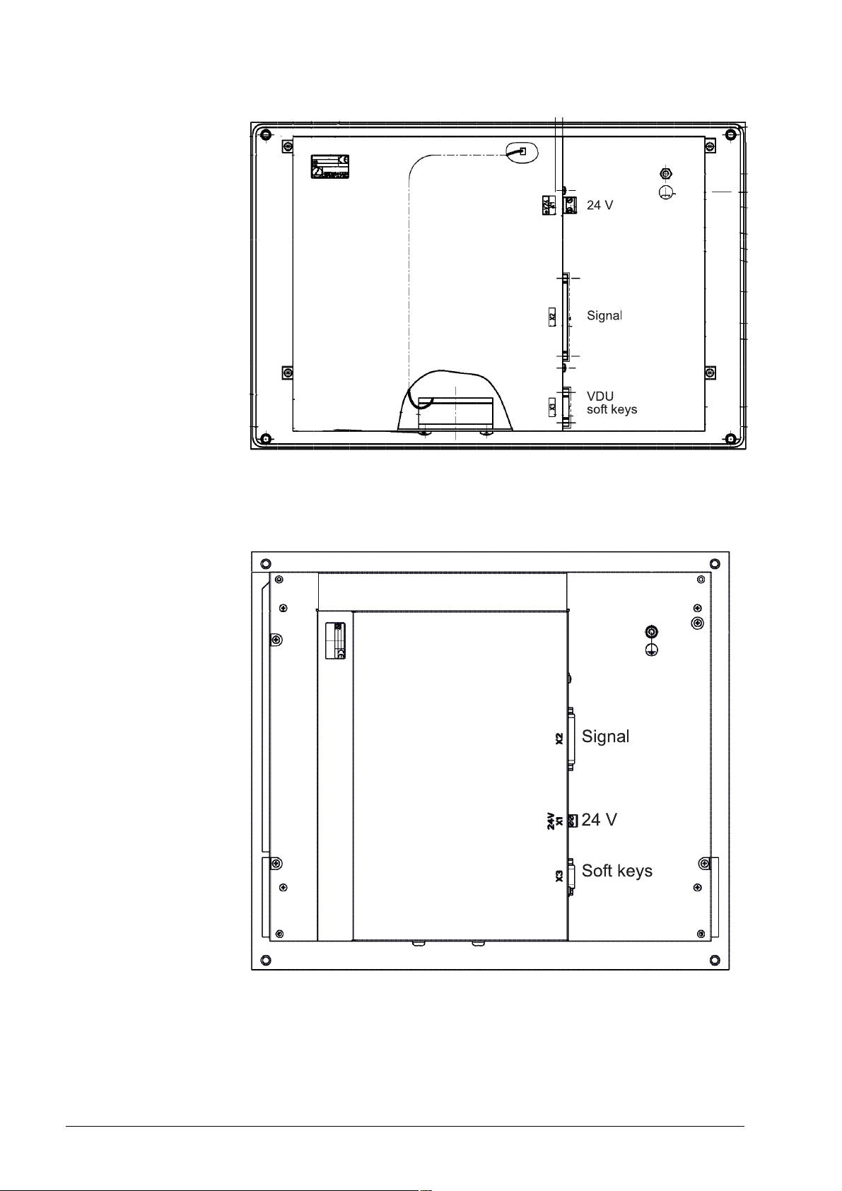
Rear view BF 120
Rear view BF 150
May 2006 21 – 355
Page 57

21 – 356 HEIDENHAIN Service Manual iTNC 530
Page 58

22 Keyboard Unit
22.1 General
The keyboard units are available with individual keys and as membrane keyboard.
The screen soft keys are connected to the keypad board.
The key signals on the control are transferred by a matrix. Every crosspoint of a SL (ScanLine)
with a RL (ReturnLine) is assigned to a certain key.
If HR 420 electronic handwheel is active, the operation of the machine via keypad is locked.
For iTNC 530 single-processor controls a TE 420 can be used; for dual-processor controls,
however, a mouse pad and additional Windows keys are required (Te 530, 530 B).
For the HEIDENHAIN programming surface smarT.NC additional keys are necessary.
(TE 530 B, TE 520 B).
22.2 Front View of the Keyboard Units
TE 420
May 2006 22 – 357
Page 59

TE 530 (with mouse pad and additonal Windows keys)
TE 530 B (with additonal smarT.NC keys)
22 – 358 HEIDENHAIN Service Manual iTNC 530
Page 60

TE 520 B (with additional smarT.NC keys, without mouse pad)
22.3 Possible Causes of Error
Note
Defective keys cannot contact any more or are in continuous contact.
Strong contramination --> Key gets caught
Jammed chips --> Key gets caught
Defective contact --> Key does not report to the control any more
Penetrated liquid
Defective keypad board
Defective cable between screen and keypad (screen softkeys)
Defective cable between keypad and control
Defective interface on the control
Worn potentiometer wiper
Defective mouse pad
May 2006 22 – 359
Page 61

22.4 Checking the Keys
This includes the keys on the TE keypad unit and the keys (soft keys) on the BF flat-panel
display. The soft keys of the screen are connected by ribbon cable with the keypad board.
Correct operation?
Make sure that the key in the selected operating mode really functions.
--> Ask the machine operator or look it up in the User's Manual!
Visual inspection First check the keypad visually!
Is the key strongly contaminated (grease, dust, oil, etc.)?
Are there jammed chips?
The key may thus get caught.
In such a case, the keypad must be cleaned carefully.
DANGER
When liquid cleaning agents have be used, the electrical units must dry completely before
they are operated again.
Does the control receive the key signal?
To be sure you can observe the key code in PLC word W274 when
the keys are pressed:
Press EMERGENCY STOP.
Reboot the control.
Do not acknowledge the "Power interrupted" message.
Call the PLC table for the words (see “The TABLE Function” on page 10 – 76).
Press the key to be examined and check if the display changes to the valid key code and/or
the key reacts correspondingly. --> See note.
Text file KEYTEST.A
Note
When examining these keys, please check if the following reactions are generated:
END --> To leave the PLC table.
PG UP --> The cursor jumps one page up.
PG DN --> The cursor jumps one page down.
GOTO --> A target must be entered at the top of the screen
(press NO ENT to exit!).
END BLOCK --> To leave the PLC table.
MACHINE OPERATING MODES --> The corresponding machine operating mode is called.
As an alternative to test whether the control receives the key signals, you can create a text file,
e.g. KEYTEST.A.
The keys pressed on the ASCII field (blue keys) are displayed directly. Other keys mostly
generate the message "Key non-functional" or a corresponding reaction, e.g., change to a
machine operating mode.
22 – 360 HEIDENHAIN Service Manual iTNC 530
Page 62

Principle of the key matrix
Is a line (cable, board) or the key defectibe?
The keys are evaluated via a matrix. Every key is located above a crosspoint of SL (= scan line)
and RL (= return line). --> see “Key Matrix of the Keyboard Units” on page 22 – 367 or see “Key
Matrix of the Keyboard Units” on page 22 – 382.
Inspection of the keyboard
Use the key matrix to find a key that is
selected by the same RL line as the
defective key (and which functions in
the selected operating mode).
Press this key.
No
Any reaction?
Yes
Use the key matrix to find a key that is
selected by the same SL line as the
defective key (and which functions in
the selected operating mode).
Press this key.
No
Any reaction?
The line to the matrix is interrupted.
Check the keyboard cable (measure
the cable, try replacement, etc.)
and the connectors.
Is the keyboard PCB defective?
Yes
The matrix lines (keyboard cable,
keyboard PCB) are in order.
The contact of the key is
probably defective.
May 2006 22 – 361
Page 63

Measuring setup with test adapter
The functioning of the keypad connected is tested with the following setup.
The following special appliance is required.
--> see “Test Adapter, ID 375830-01” on page 29 – 456:
Switch off the machine.
Disconnect the keypad cable on connector X45 of the MC.
Connect the keypad cable to the test adapter.
Connect the measuring lines of a multimeter to the pin sockets of the test adapter.
Use the correspondig key matrix with the pin layout. --> see “Key Matrix of the Keyboard
Units” on page 22 – 367.
Set the multimeter to ohm measurement or continuity test.
Press the key to be examined. If it functions, the resistance value from SL to RL approaches
zero (regard the resistance of the measuring lines).
Note
Limitations for keypads as of TE 5xx:
A continuity test of the cross points of scan lines (SL) and the return line 0 (RL 0) is not
possible. There are logical gates between RL 0 and the corresponding keys. These gates
serve as keypad identifier as of TE 5 xx.
A direct ohmic measuring is thus not possible.
22 – 362 HEIDENHAIN Service Manual iTNC 530
Page 64

The functioning of the keypad interface on the MC can also be tested with the test adapter:
Disconnect the keypad from the MC.
Connect the test adapter instead to connector X45 of the MC.
You can now simulate the pressing of keys by bridging the corresponding pin sockets on the
test adapter.
(Please refer again to the key matrix which sockets must be connected.)
Caution
Do not generate a short circuit of the potentiometer voltage (PIN 36 and 37)!
Note
As the keypad interface X45 on the MC is designed as female, you can also connect the pins
with a wire bridge and thus conduct a simulation by pressing the keys.
May 2006 22 – 363
Page 65

22.5 Checking the Potentiometers
Potentiometer values in the PLC-TABLE
Potentiometer values in the oscilloscope
You can use the PLC table to determine whether the control receives the potentiometer signal.
The potentiometer setting is shown in the following PLC words:
W492 (=S override)
W494 (= F override)
Proceed as follows:
Press EMERGENCY STOP.
Call the PLC table for the words (see “The TABLE Function” on page 10 – 76).
Place the cursor at W492 or W494.
Select the decimal display.
Turn the potentiometer to be examined.
Check if the display can be changed from 0 to 15000 (with nonlinear characteristic curve)
or 0 to 150 (with linear characteristic curve).
The characteristic curve is defined in MP 7620 bit 3.
With the integrated oscilloscope you can also record the condition of PLC words.
-> see “Integrated Oscilloscope” on page 8 – 49.
The advantage of this method is that possible wiper interruptions of the potentiometers can be
recognized better than in the PLC TABLE.
For this investigation the machine must be switched on completely!
22 – 364 HEIDENHAIN Service Manual iTNC 530
Page 66

Measuring setup with test adapter
Procedure:
Switch off the machine.
Insert the measuring adapter at the MC connector X45 between MC and TE cable.
Switch the machine on again.
Using a multimeter, check the wiper voltages of the potentiometers.
Potentiometers PIN Voltage range
Feed rate override F% 37 = 0V / 35 = Wiper pot 0 ... approx. + 5 V
Spindle override S% 37 = 0V / 34 = Wiper pot 0 ... approx. + 5 V
May 2006 22 – 365
Page 67

22.6 Checking the Touch Pad
The touch pad on the TE 530 and 530B keypads functions also for the single-processor control
in connection with the Windows operating system of a dual-processor control and as of software
version smarT.NC!
This touch pad is not connected to the MC via keypad connector X45 but with a USB cable to
MC connector X141.
If the touch pad does not function, carry out the following test to find out if the touch pad itself
or the interface on the control is defective:
Try the second USB connector X142 on the control.
Note
If a new mouse or touch pad is connected, it functions only after the control has been
switched off and on again.
Try a commercially available mouse on the USB connectors of the control (the mouse should
function on a Windows 2000 PC).
If necessary, you can also extend the USB cable of the touch pad, connect it to a laptop and
test the functioning (the laptop must be equipped with a Windows operating system with the
corresponding mouse driver).
Note
As the touch pad is managed by Windows, there are also the corresponding Windows
settings. --> "My computer/Control Panel/Mouse…"
22 – 366 HEIDENHAIN Service Manual iTNC 530
Page 68

22.7 Key Matrix of the Keyboard Units
TE 420
X2 pin key 1 2 3 4 5 6 7 8 9 17 18 19 28 29 31 32 20 21 22 23 24 25 26 27
RL0 1 2 3 4 5 6 7 8 16 17 18 19 20 21 22 SL0 1 2 3 4 5 6 7
XX
XX
XX
XX
XX
XX
XX
XX
XX
XX
XX
XX
XX
XX
XX
XX
XX
XX
XX
XX
XX
XX
XX
XX
XX
XX
May 2006 22 – 367
Page 69

X2 pin key 1 2 3 4 5 6 7 8 9 17 18 19 28 29 31 32 20 21 22 23 24 25 26 27
RL0 1 2 3 4 5 6 7 8 16 17 18 19 20 21 22 SL0 1 2 3 4 5 6 7
XX
XX
XX
XX
XX
XX
XX
XX
XX
XX
;
XX
XX
XX
:
XX
XX
XX
XX
XX
XX
XX
XX
XX
XX
XX
XX
XX
XX
22 – 368 HEIDENHAIN Service Manual iTNC 530
Page 70

X2 pin key 1 2 3 4 5 6 7 8 9 17 18 19 28 29 31 32 20 21 22 23 24 25 26 27
RL0 1 2 3 4 5 6 7 8 16 17 18 19 20 21 22 SL0 1 2 3 4 5 6 7
XX
XX
XX
XX
X X
X X
XX
X X
X X
X X
X X
X X
X X
XX
XX
XX
XX
XX
XX
XX
XX
XX
XX
XX
XX
XX
XX
May 2006 22 – 369
Page 71

X2 pin key 1 2 3 4 5 6 7 8 9 17 18 19 28 29 31 32 20 21 22 23 24 25 26 27
RL0 1 2 3 4 5 6 7 8 16 17 18 19 20 21 22 SL0 1 2 3 4 5 6 7
XX
XX
XX
XX
XX
XX
X X
X X
X X
X X
XX
X X
X X
X X
XX
XX
X X
X X
XX
XX
XX
X X
XX
XX
X X
XX
X X
22 – 370 HEIDENHAIN Service Manual iTNC 530
Page 72
X2 pin key 1 2 3 4 5 6 7 8 9 17 18 19 28 29 31 32 20 21 22 23 24 25 26 27
RL0 1 2 3 4 5 6 7 8 16 17 18 19 20 21 22 SL0 1 2 3 4 5 6 7
X X
X X
X X
X X
X X
XX
XX
XX
XX
XX
X X
May 2006 22 – 371
Page 73

TE 530, TE 530 B, TE 520 B
X2 Pin
Key
ESC
PRT
SC
SCROL
BREAK
INS
DEL
HOME
END
PG
UP
PG
DN
X
1 RL0
2 1
3 2
4 3 X
5 4
6 5
7 6
8 7
9 8
12 11 X X
13 12 X X
14 13 X
15 14 X
16 15
17 16 X
18 17
19 18
28 19
29 20 XX
31 21
32 22 X X X
33 23 X X
20 SL0
21 1
22 2X
23 3X X X
24 4X X
25 5XX
26 6XXX
27 7XX XX
22 – 372 HEIDENHAIN Service Manual iTNC 530
Page 74

X2 Pin
Key
~
9
8
7
@
!
2
1
$
#
3
%
5
4
&
7
6
(
*
8
9
_
)
-
0
1 RL0 X
2 1X
3 2X
4 3
5 4
6 5
7 6
8 7
9 8
12 11
13 12
14 13
15 14
16 15
17 16 X X
18 17 X X
19 18 X X
28 19 XX
29 20 XX
31 21 X
32 22 X
33 23
20 SL0 X XXXX
21 1 XXXXXXX
22 2
23 3
24 4XXX
25 5
26 6
27 7
May 2006 22 – 373
Page 75

X2 Pin
Key
1 RL0 X
2 1X
3 2X
4 3X
5 4
6 5
7 6
8 7
9 8
12 11
13 12
14 13
15 14
16 15
17 16 X
18 17 X X
19 18 XX
28 19 XX
29 20 X
31 21 X
32 22 X X
33 23
20 SL0 X X
21 1
22 2 XXXX
23 3 XXXXXXXX
24 4
25 5
26 6X
27 7
+
x
=
Y
5
4
TAB
6
Q
W
E
R
Y
T
U
I
22 – 374 HEIDENHAIN Service Manual iTNC 530
Page 76

X2 Pin
Key
1 RL0 X
2 1X
3 2X
4 3X
5 4
6 5
7 6
8 7
9 8
12 11
13 12
14 13 X
15 14
16 15
17 16 X
18 17 XX
19 18 XX
28 19
29 20 X
31 21 X X
32 22 X
33 23 X
20 SL0
21 1
22 2 X XXXX
23 3X
24 4XX XX
25 5 XXX
26 6X
27 7X
O
P
{
[
{
|
[
\
1
Z
2
CAPS
LOCK
3
A
S
D
F
G
May 2006 22 – 375
Page 77

X2 Pin
Key
1 RL0 X
2 1X
3 2X
4 3X
5 4
6 5
7 6
8 7
9 8
12 11
13 12
14 13
15 14
16 15
17 16 X X
18 17 XX
19 18
28 19 X X
29 20 X X
31 21 X
32 22 X
33 23 X
20 SL0 X
21 1XXXX
22 2XX
23 3
24 4XXX
25 5XX
26 6 X
27 7 XX
H
J
K
L
:
"
;
IV
0
SHIFT
-
links
/
+
X
Z
C
22 – 376 HEIDENHAIN Service Manual iTNC 530
Page 78

X2 Pin
Key
V
B
N
M
>
<
,
.
SHIFT
?
rechts
/
V
Q
CTRL
links
WIN
links
1 RL0
2 1
3 2 XX
4 3
5 4
6 5
7 6X
8 7
9 8X
12 11
13 12
14 13
15 14 X
16 15 X
17 16
18 17
19 18 X X
28 19 X X
29 20
31 21 X X X
32 22
33 23 X
20 SL0 X
21 1X
22 2
23 3X
24 4X
25 5XX
26 6X X X X X
27 7XX X
May 2006 22 – 377
Page 79

X2 Pin
Key
ALT
links
SPACE
ALT
rechts
WIN
rechts
WIN
Kont
Ctrl
rechts
CE
DEL
P I
NO
ENT
ENT
END
1 RL0 XX
2 1 X
3 2
4 3XX
5 4XX
6 5
7 6
8 7
9 8
12 11 X X
13 12
14 13 X
15 14
16 15 X
17 16 X
18 17
19 18
28 19
29 20
31 21
32 22
33 23 X
20 SL0 X X
21 1X
22 2X
23 3
24 4
25 5XXXXXX
26 6
27 7X XX
22 – 378 HEIDENHAIN Service Manual iTNC 530
Page 80

X2 Pin
Key
PGM
MGT
APPR
ERR
FK
DEP
CHF
L
CALC
MOD
HELP
CR
CT
RND
CC
1 RL0
2 1 X
3 2
4 3
5 4X
6 5X X X
7 6X XX
8 7X X X
9 8XXXX
12 11
13 12
14 13
15 14
16 15
17 16
18 17
19 18
28 19
29 20
31 21
32 22
33 23
20 SL0 X
21 1X
22 2XXXX
23 3XXXX
24 4XXX X
25 5
26 6
27 7 X
May 2006 22 – 379
Page 81

X2 Pin
E
Key
C
TOUC H
PROB
CYCL
DEF
CYCL
CALL
LBL
LBL
SET
CALL
STOP
1 RL0 X X
2 1X X
3 2 XX
4 3X X
5 4X X X X
6 5X
7 6X
8 7X
9 8
12 11
13 12
14 13
15 14
16 15
17 16
18 17
19 18
28 19
29 20
31 21
32 22
33 23
20 SL0 X X
21 1XXXX
22 2 X
23 3X
24 4
25 5
26 6X X XXX
27 7X X
22 – 380 HEIDENHAIN Service Manual iTNC 530
Page 82

X2 Pin
Key
TOOL
DEF
TOOL
CALL
PGM
CALL
GOTO
1 RL0
2 1
3 2
4 3
5 4X
6 5XXX
7 6X X
8 7X X X
9 8
10 9XXX
12 11
13 12
14 13
15 14
16 15
17 16
18 17
19 18
28 19
29 20
31 21
32 22
33 23
20 SL0 X X X X X
21 1 X
22 2 X
23 3
24 4
25 5XXX
26 6XX
27 7
Note
The two keys left of the touch pad do not belong to the key matrix!
If these keys are pressed, the signal is transmitted to the control via USB interface.
May 2006 22 – 381
Page 83
22.8 Key Matrix of the Keyboard Units
Note
The keys pressed are also recorded in the log. The SK1 key is entered as soft key 0, the SK2
key as soft key 1 and so on.
The soft keys are numbered serially from left to right.
BF 120
a
X1 pin
X2 pin
b
key
a
9 8 7 6 1 2 3 4
13 14 15 16 20 21 22 23
RL12 RL13 RL14 RL15 SL0 SL1 SL2 SL3
XX
XX
XX
SK1
SK2
SK3
SK4
SK5
SK6
SK7
SK8
XX
XX
XX
XX
XX
XX
XX
XX
XX
a. Connector on the keyboard unit
b. Key on visual display unit
X1: Connection for ribbon cable display unit => keyboard unit (plug-type connector)
X2: Connection for cable keyboard unit => MC (D-Sub 37-pin)
SK = Soft key (SK1..SK8 from left to right)
22 – 382 HEIDENHAIN Service Manual iTNC 530
Page 84

BF 150
X1 pin
X2 pin
b
key
a
9 8 7 6 1 2 3 4 5
a
13 14 15 16 20 21 22 23 24
RL12 RL13 RL14 RL15 SL0 SL1 SL2 SL3 SL4
XX
XX
XX
XX
SK1
SK2
SK3
SK4
SK5
SK6
SK7
SK8
XX
XX
XX
XX
XX
XX
XX
XX
XX
XX
XX
XX
XX
XX
X X
a. Connector on the keyboard unit
b. Key on visual display unit
X1: Connection for ribbon cable display unit => keyboard unit (plug-type connector)
X2: Connection for cable keyboard unit => MC (D-Sub 37-pin)
SK = Horizontal soft keys (SK1..SK8 from left to right)
MF = Vertical soft keys (MF1..MF6 from top to bottom)
May 2006 22 – 383
Page 85

22 – 384 HEIDENHAIN Service Manual iTNC 530
Page 86

23 Machine Operating Panel
23.1 General
For machines with up to four axes, HEIDENHAIN offers the MB 420 machine operating panel.
It is normally mounted below the TNC keyboard.
The machine operating panel is connected to connector X46 of the MC.
The keys and buttons of the MB 420 are transmitted as PLC inputs to the control.
The MB 420 is provided with 8 PLC outputs (e.g., the lamps of the buttons can be controlled).
If a machine operating panel (tableau) from the machine tool buildler is used, please see the
corresponding circuit diagram. It shows the wiring of the keys.
Caution
HEIDENHAIN recommends to check the function of the EMERGENCY STOP switch on the
machine operating panel or operating tableau regularly!
May 2006 23 – 385
Page 87

23.2 Checking the Power Supply
The MB 420 is supplied with 24 V PLC voltage on X1/PIN 34, 35 with 0 V and on X1/PIN 36, 37.
Measure if the power supply is in order!
Measuring setup with test adapter
Procedure:
Switch off the machine.
Insert the test adapter at the MC connector X1 between MC 420 and connecting cable.
Switch the machine on again.
Using a multimeter, check the supply voltage on the corresponding PINs.
23 – 386 HEIDENHAIN Service Manual iTNC 530
Page 88

23.3 Checking the Keys
Possible causes of error
Visual inspection First check the keypad visually!
Strong contramination --> Key gets caught
Jammed chips --> Key gets caught
Defective contact --> Key does not report to the control any more
Defective keypad board
Defective cable MB control
Defective interface on the control
Note
Due to an interruption of the NC stop signal (lowactive) between MB and control, the
machine cannot be traversed any more. The same problem is caused if the NC-stop key gets
caught.
Is the key strongly contaminated (grease, dust, oil, etc.)?
Are there jammed chips?
The key may thus get caught.
In such a case, the MB must be cleaned carefully.
DANGER
When liquid cleaning agents have be used, the electrical units must dry completely before
they are operated again.
May 2006 23 – 387
Page 89

Does the control receive the key signal?
The keys and buttons of the MB 420 are assigned to PLC inputs:
I
136
128
129
I
I
I
135
148
130
I
I
134
137
I
I
I
133
149
I
I
I
131
132
138
139
140
I
I
I
143
145
I
I
144
141
I
I
150
I
I
142
Two other inputs (I151 and I152) can be wired via terminal row X3:
Terminal X3 Assignment
1 I151
2 I152
3+24 V
146
147
I
I
The inputs are connected to the control (MC, connector X46) via connecting lines X1.
Connectors and pin layouts on MB 420 --> see “Machine Operating Panel” on page 13 – 199.
The function of the MB keys can be checked via the table for the PLC inputs:
Press EMERGENCY STOP.
Call the table with the PLC inputs. -->see “The TABLE Function” on page 10 – 76.
Press the keys.
The corresponding inputs must change to 1!
Exception: I147 = NC stop, changes to 0 (line-break proof!) if activated.
Note
You can measure the input voltages, e.g. on terminal X3 of the MB 420 or via test adapter
on connector X1. --> see “Test Adapter, ID 375830-01” on page 29 – 456.
23 – 388 HEIDENHAIN Service Manual iTNC 530
Page 90

23.4 Checking the Outputs
The MB 420 is provided with 8 PLC outputs (e.g., the lamps of the buttons can be controlled).
These outputs are located on the connecting leads X1 and also on terminal block X4:
Terminal X4 Assignment
1O0
2O1
3O2
4O3
5O4
6O5
7O6
8O7
90 V
The function can be checked via the table for the PLC outputs:
Call the table with the PLC outputs. --> see “The TABLE Function” on page 10 – 76.
Establish the conditions for setting the corresponding output (keystroke, function call, etc.).
If necessary, use the User's Manual or the circuit diagram of the machine or ask the machine
manufacturer.
The corresponding outputs must change the condition!
You can now find out, e.g., whether a lamp is defective or is not controlled correctly.
Note
You can measure the output voltages, e.g. on terminal X4 of the MB 420 or via test adapter
on connector X1. --> see “Test Adapter, ID 375830-01” on page 29 – 456.
May 2006 23 – 389
Page 91

23 – 390 HEIDENHAIN Service Manual iTNC 530
Page 92

24 Handwheel
24.1 General Information
The following handwheels can be connected to the iTNC 530 controls:
One panel-mounted HR 130 handwheel
Three HR 150 panel-mounted handwheels via the HRA 110 handwheel adapter
One HR 410 portable handwheel
One HR 420 portable handwheel with display
Shock or vibrations can cause a slight motion at the handwheel and produce an unintentional axis
movement. The threshold sensitivity is entered in MP 7660!
Portable handwheels with EMERGENCY stop button are connected to the control via a cable
adapter. The EMERGENCY STOP wiring and the wiring for the permissive keys are located in
cable adapter Id.Nr. 296466-xx.
Pin layouts and wiring (e.g., EMERGENCY STOP key and permissive key on cable adapter)
--> see “Handwheels” on page 13 – 183.
For information on the operation of the electronic handwheels. --> See User's Manual iTNC 530.
Caution
HEIDENHAIN recommends to check the function of the EMERGENCY STOP switch on the
handwheel regularly!
May 2006 24 – 391
Page 93

Note
The power of the handwheel is not monitored!
A defective handwheel or a handwheel with penetrated humidity may influence the 12 V
supply voltage of the control. This can lead to various disturbances of the control. It is
possible that error messages are displayed that do not immediately refer to a defective
handwheel.
In such a case, unscrew the handwheel inclusive cable from the adapter block on the
operating panel. Connect the dummy plug Id.Nr. 271958-03 instead or bridge the handwheel
in the EMERGENCY STOP chain. Set MP 7640 to "No handwheel" (or a handwheel error
message will be generated).
You can now observe if the mentioned disturbances or error messages on the control are
still generated.
Possible causes of error
Tips for trouble-shooting
The portable handwheel fell down and was damaged
Strong contramination --> Key functions are possibly damaged.
Jammed chips --> Key gets caught
Defective contact --> Key does not report to the control any more
Defective potentiometers
Defective board
Defective handwheel encoder
Humidity
Defective handwheel cable
Error in cable adapter --> Continuous EMERGENCY STOP or permissive keys nonfunctional
Shock or vibrations --> Undesired traverse motions
Handwheel interface on MC defective
Switch the control display to "Nominal value" and observe if the display changes while turning
the HR.
Check the HR, cable, contacts, etc. visually
If required, check the PLC inputs and markers --> See following pages
If required, check the potentiometers and switches --> See following pages
Connect the test adapter between connector X23 of the MC and handwheel and measure the
+12 V voltage (see “Test Adapter, ID 375830-01” on page 29 – 456)
If available, connect a dimensionally identical handwheel and test the functioning.
MC
X 23
Test adapter
ID 375830-01
24 – 392 HEIDENHAIN Service Manual iTNC 530
Page 94

24.2 HR 420 Portable Handwheel with Display
24.2.1 Checking the Keys
The keys cannot contact any more (defective contact, line, etc.) or are in continuous contact
(adhesion of the key by strong contamination, jammed chips, etc.).
With the PLC diagnostic functions TABLE or LOGIC DIAGRAM you can check the function of
many handwheel keys my means of the corresponding PLC markers:
Press EMERGENCY STOP.
Activate the HR 420 (press the handwheel symbol on the HR 420)
Call the table with the PLC markers and start the logic diagram. --> see “PLC Diagnosis” on
page 10 – 73.
Press the handwheel keys.
Check whether the corresponding markers are set.
MP7641 defines if a HR 420 with or without detent is used or if the keys on the handwheel are
evaluated by the NC or the PLC.
All keys are evaluated by the NC. Certain keys are mapped on markers.
F1 F2 F3 F4 F5
XYZIVV
Hand-
¦
–
(M4667)
Spindle
start
(M4664)
Spindle
stop
(M4665)
Note
Only if M4660 is set (HR 420 active), other markers can be set or reset.
wheel
active/
inactive
Rapid
traverse
(M4663)
Actual-to-
nominal
value
transfer
CTRL
(M4668)
Ø
+
(M4666)
NC start
(M4661)
NC stop
(M4662)
Keys that are not mapped in markers can be checked easily by controlling if a function is called
by pressing the corresponding key or if there is a reaction on the screen.
May 2006 24 – 393
Page 95

24.2.2 Checking the Potentiometers
The override potentiometers of the HR 420 are active up to NC software version as soon as the
handwheel operation was selected!
The potentiometers of the keyboard are then inactive.
DANGER
By switching from the keyboard to the HR 420 and vice versa, the feed rate or the spindle
speed can change depending on the corresponding potentiometer setting.
As of NC software version 34049x-xx (with smarT.NC programming surface), the
potentiometers of the keyboard are still active after selecting the handweel operating mode.
To test the handwheel potentiometers, you must switch over correspondingly:
Press the CTRL and Handwheel keys in the HR 420. --> The TNC shows the soft-key menu
for selecting the potentiometers on the handwheel display.
Press the HW soft key to activate the handwheel potentiometer.
Potentiometers on HR 420 active
If you have activated the potentiometers on the handwheel, you must reactivate the
potentiometers of the machine operating panel before deselecting the handwheel. Proceed as
follows:
Press the CTRL and Handwheel keys in the HR 420. --> The TNC shows the soft-key menu
for selecting the potentiometers on the handwheel display.
Press the KBD soft key to activate the potentiometers of the machine operating panel.
24 – 394 HEIDENHAIN Service Manual iTNC 530
Page 96

By means of W494 the function of the feed-rate override potentiometer, and by means of
W492 the function of the spindle override potentiometer can be controlled:
Press EMERGENCY STOP.
Activate the HR 420 (press the handwheel symbol on the HR 420).
Activate the handwheel potentiometers (as of NC software version 34049x-xx).
Call the PLC table with the words. --> see “The TABLE Function” on page 10 – 76.
Select the decimal display.
Turn the potentiometer to be investigated.
The value of W492 or W494 changes between 0 and 10000 with nonlinear or between 0
and 100 with linear curve of the potentiometer (the curve is defined in MP 7620 bit 3).
Note
These PLC words can also be shown in the integrated oscilloscope.
--> see “Checking the Potentiometers” on page 22 – 364.
May 2006 24 – 395
Page 97

24.3 HR 410 Portable Handwheel
24.3.1 Checking the Keys
The keys cannot contact any more (defective contact, line, etc.) or are in continuous contact
(adhesion of the key by strong contamination, jammed chips, etc.).
With the PLC diagnostic functions TABLE or LOGIC DIAGRAM you can check the function of the
handwheel keys my means of the corresponding PLC inputs:
Press EMERGENCY STOP.
Call the table with the PLC inputs or start the logic diagram.
--> see “PLC Diagnosis” on page 10 – 73.
Press the handwheel keys.
Check whether the corresponding inputs change to 1.
MP7645 determines whether the handwheel keys are evaluated by the NC or the PLC.
Evaluation of the keys via the NC. --> MP7645.0 = 0
XIV
YV
Z
Low feed
rate
Medium
feed rate
High feed
rate
–+
O109
I173
All keys are evaluated by the NC except the keys A, B and C!
O110
I174
O111
I175
24 – 396 HEIDENHAIN Service Manual iTNC 530
Page 98

Evaluation of the keys via the NC. --> MP7645.0 = 1
Note
Ask the machine manufacturer if MP 7645.0 can be changed for test purposes. It is possible
that this is not permitted by the PLC program.
O96
I160
O98
I162
O100
I164
O104
I168
I171 I172
O109
I173
O105
I169
O110
I174
O97
I161
O99
I163
O103
I167
O106
I170
O111
I175
All keys are evaluated by the PLC!
May 2006 24 – 397
Page 99

24.4 HR 150 Panel-Mounted Handwheels with HRA 110 Handwheel Adapter
With the handwheel adapter HRA 110 you can connect two or three HR 150 panel-mounted
handwheels to the TNC.
The first and second handwheels are assigned to the X and Y axes. The third handwheel can
be assigned either through a selection switch (option) or with MP7645.
HR 150
An additional switch enables you to select, for example, the interpolation factor for the
handwheel. The current position of the step switch is evaluated by the PLC.
24.4.1 Checking the Switch
max. 20 m
HRA 110
X1
X2
X3
X31 24 V
S2
S1
X23
Achswahl (Option)
AXIS SELECTION (OPTIONAL)
Unterteilungsfaktorwahl (Option)
INTERPOLATION FACTOR (OPTIONAL)
X23 (LE)
Id.-Nr. 270 909..
max. 50 m
The function of the selective switches can be checked via the PLC table for the inputs:
Press EMERGENCY STOP.
Call the table with the PLC inputs. --> see “The TABLE Function” on page 10 – 76.
Turn the selective switches.
Using the following tables, check whether the corresponding inputs change to 0.
24 – 398 HEIDENHAIN Service Manual iTNC 530
Page 100

Assignment of the switch positions to the PLC inputs
The tables below list the assignments of switch positions of S1 and S2 to the
PLC inputs I160 to I175.
The two switches work with a 0 V logic circuit.
Example:
If switch S1 is in position 3, input I162 is logically 0, and all other inputs
are logically 1.
Step switch 1: Step switch for choosing the interpolation factor
Switch position PLC input
1 (at the left stop) I160
2 I161
3 I162
4 I163
5 I164
6 I165
7 I166
8 (at the right stop) I167
Step switch 2: Axis selection switch
Switch position PLC input
1 (at the left stop) I168
2 I169
3 I170
4 I171
5 I172
6 I173
7 I174
8 (at the right stop) I175
May 2006 24 – 399
 Loading...