


Motion Sensing
Porch Light
SL-4305
Features
•Light comes on when motion is detected.
•Automatically turns light off.
•Photocell keeps the light off during daylight hours.
This package includes:
•Porch Light
•Easy to use Universal Mounting Bracket
•Mounting Hardware
•Wire Nuts
•Lens Shield
Requirements
•The light control requires 120 volts AC.
•If you want to use Manual Mode, the control must be wired through a switch.
•Some electrical codes require installation by a qualified electrician.
Before installation,record the model number listed inside the fixture.Attach receipt in case of possible warranty issues.
Model Number:
OPERATION
Mode: |
On-Time |
Works: Day |
Night |
Test |
5 Seconds |
x |
x |
Auto |
1, 5, or 10 Min |
|
x |
Manual |
To Dawn* |
|
x |
* resets to Auto Mode at dawn.
Note: When first turned on wait about 1 1/2 minutes for the circuitry to calibrate.
TEST
Set the ON-TIME switch ON-TIME |
||||||||
on the sensor to TEST. |
|
|
|
|
|
|
|
|
|
|
|
|
|
|
|
|
|
|
|
|
|
|
|
|
|
|
|
TEST 1 5 10 MIN |
|||||||
AUTO |
||||||||
|
|
|
|
|
|
|
||
Set ON-TIME switch to |
|
ON-TIME |
||||||
|
|
|
|
|
|
|
|
|
1, 5, or 10 minutes. |
|
|
|
|
|
|
|
|
|
|
|
|
|
|
|
|
|
TEST 1 5 10 MIN
MANUAL MODE
Manual mode only works at night because daylight returns the sensor to AUTO.
Flip the light switch off for one second then back on to toggle between AUTO and MANUAL MODE.
Manual mode works only with the ON-TIME switch in the 1, 5, or 10 position.
1 Second OFF
then...
... back on.
Mode Switching Summary
|
TEST |
|
|
|
|
ON-TIME Switch at 1, 5, or |
|
|
|
|
|
|
|
10 minutes |
|
|
AUTO |
|
|
|
|
|
Flip light switch off |
|
|
|
|
|
|
|
|
|
|
|
|
|
|
|
for one second then |
MANUAL MODE |
|
|
|
back on* |
|||
|
|
|
|||||
* If you get confused while switching modes, turn the power off for one minute, then back on. After the calibration time the control will be in the AUTO mode.
© 2007 HeathCo LLC |
598-1184-04 |

Disassemble Light Fixture
1.Remove two decorative nuts from light fixture cover.
2.Remove cover from base.
Light Fixture Base
Light Fixture Cover
 Decorative Nut
3.Remove two decorative nuts from fixture screws in universal mounting bracket.
4.Remove universal mounting bracket from base.
 Universal
Mounting
Bracket
Decorative Nut
|
ITIV |
ITY |
||
SENS |
|
|
||
|
|
|
|
|
|
- M |
- HI |
|
|
LO |
|
|
|
|
|
|
|
10 |
MIN |
|
1 |
5 |
|
|
|
IME |
|
||
TESTON-T |
|
|
|
|
Install universal Mounting Bracket
For best performance, mount the fixture at least 8 feet (2.4 m) above the ground.
 WARNING: Turn power off at circuit breaker or fuse.
1.Tighten the two fixture screws finger tight.
2.Attach universal mounting bracket to junction box securely with the two screws provided.
 Junction Box
Universal Mounting
Bracket
Junction Box Screw
 Fixture Screw (Tightened
Finger Tight)
Wiring Light Fixture
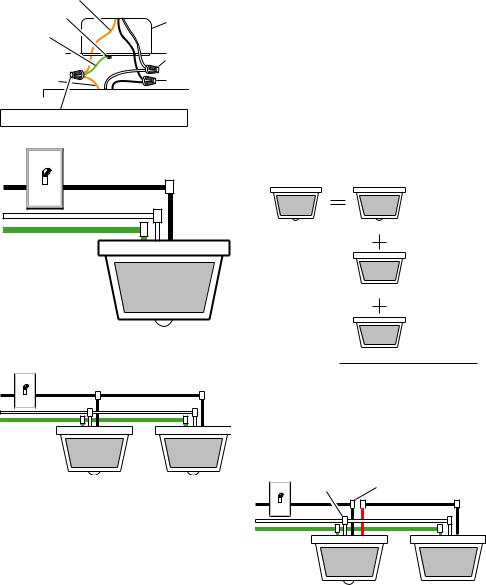
1.Connect the junction box wires and the fixture wires together as shown in the following diagrams.
 CAUTION: DO NOT remove wire connector from RED wire or connect the RED wire unless you want to control other lights from this motion sensor fixture.
2. Twist and secure wires with wire nuts.
Note: If you have a metal junction box use the recommended grounding method shown in the following illustration.If you are uncertain about the grounding method, consult your local building code.
598-1184-04
Bare Ground Wire |
|
|
Ground Screw |
Metal Junction |
|
|
||
Pigtail (not |
Box |
|
supplied) |
|
|
Fixture Bare |
White to White |
|
Black to Black |
||
Ground Wire |
Recommended Grounding Method
Black to Black
White to White
Ground to Ground
One Motion Sensing Light
Black to Black
White to White
Ground to
Ground
Two Motion Sensing Lights (Working Independently)
Other Wiring Options
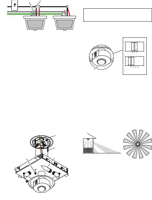
This fixture can be wired to control another standard or motion sensing light fixture(s). See the following wiring diagrams for proper connections.
Note: All wiring should be run in accordance with the National Electrical Code through conduit or another acceptable means. Contact a qualified electrician if there is any question as to the suitability of the system.
When controlling an additional light fixture(s), the maximum wattage of the motion sensor on this fixture should be observed. See illustration below for an example of a maximum lamp wattage load calculation.
Maximum Lamp Wattage Rating for Light Fixture – 100 Watts
Maximum Load for CONTROLLING Fixture Motion Sensor –
500 Watts
Maximum Lamp Wattage Rating for Light Fixture – 100 Watts
CONTROLLED Fixture 1
Maximum Lamp
Wattage Rating
for Light Fixture –
100 Watts
CONTROLLED Fixture 2
TOTAL Load for Motion Sensor –
300 Watts (200 Watts Remaining)
IMPORTANT: When determining the maximum lamp wattage rating of the fixture to be controlled, refer to the maximum lamp wattage label on the fixture and not the wattage rating on the lamp(s) currently installed in the fixture.
White to White |
Black to Black |

 Red to Black
Ground to
Ground
Motion Sensing |
Standard Light |
Light |
Fixture |
Wiring Motion Sensing Light to Control Standard
Fixture
598-1184-04
White to White Black to |
Black to Red |
Black |
and Black |

 Red to Black
Ground to
Ground
Motion Sensing |
Controlled Motion |
Light |
Sensing Light |
Wiring Motion Sensing Light to Control Another Motion Sensing Light
It is also possible to wire two motion sensing lights so that either unit will turn on both lights at the same time(dualcontrolledsystem).Itisrecommendedthat onlypeoplewithelectricalwiringexperienceattempt this configuration. Please call our customer service number (1-800-858-8501) before attempting this wiring. If the dual controlled wiring is not done correctly, it can destroy both motion sensing fixtures and void your warranty.
Install Fixture Base to Junction Box
1.Push wires into the junction box.
2.Slide light fixture base onto fixture screws and tighten decorative nuts snugly against the base.
3.Install four candelabra base light bulbs (25 Watts maximum each).
4.Refer to TESTING section before installing cover.
5.After switches are set and testing is complete, use the 2 decorative nuts to install the cover.
|
Junction Box |
|
Fixture Screw |
|
25 Watt Candelabra |
Decorative Nut |
Base Bulb |
SENS |
ITIVITY |
|
|
|
|
|
|
LO - |
M - HI |
|
|
|
|
10 MI |
N |
1 |
5 |
|
|
TESTON-TIME |
|
||
Testing
1. Turn on the circuit breaker and light switch.
Note: Sensor has a 1 1/2 minute warm up period before it will detect motion. When first turned on wait 1 1/2 minutes.
2.Set the SENSITIVITY switch to the “M” position and the ON-TIME switch to the TEST position.
|
|
|
|
SENSITIVITY |
SENS |
ITIVITY |
|
|
|
|
|
|
LO - M - HI |
|
LO |
- M |
- HI |
N |
|
|
5 |
10 MI |
|
|
|
|
|
|
|
TESTON-TIME |
|
|
||
Sensor |
|
|
|
TEST 1 5 10 MIN |
Lens |
|
|
|
ON-TIME |
3.Walk through the coverage area noting where you are when the lights turn on. In TEST mode, light will stay on for only 5 seconds then turn off.
4.AdjusttheSENSITIVITYtoincreaseordecrease the range as needed. Too much sensitivity may cause false triggering due to heat sources in the coverage area (see Adjustment of Coverage Area or Troubleshooting section).
5.Set the amount of TIME you want the light to stay on after motion is detected (1, 5, or 10 minutes).
360°
8 ft. (2.4 m)
30 Feet (9.1 m) in all Directions
Maximum Range |
Coverage Angle* |
|
(Top View) |
* Without lens shield installed.
598-1184-04
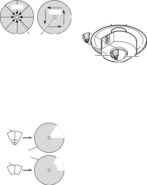
The sensor is less sensitive to motion directly towards it and more sensitive to motion across coverage area.
Motion
Motion
Sensor
Least Sensitive |
Most Sensitive |
Adjustment of Coverage Area
The sensor on this light fixture detects “motion” by the movement of heat (body heat) across the coverage area. However, following are examples of objects that also produce heat and can cause the sensor to false trigger:
• Pools of Water |
• Air Conditioners |
• Dryer Vents |
• Fenced-In Animals |
• Heating Vents |
• Automobile Traffic |
If you suspect that a heat source of this type is falsely triggering the sensor and reducing the sensitivity does not solve the problem, then a lens shield (included) can be installed. The plastic lens shield is divided into 6 sections. Each section will reduce the coverage angle by 30 degrees. Also, the tip of each section may be removed to change the effective range of the sensor.
Lens |
|
|
Shield |
Area |
|
|
Blocked |
|
|
Effective |
|
|
Coverage Area |
|
Lens |
(Top View) |
|
Area |
||
Shield |
||
|
Blocked |
Portion 
Removed
598-1184-04
1.Break off the amount of lens shield needed to block the desired area of coverage.
2.Cut desired amount of foam tape needed to adhere the lens shield to the sensor lens.
3.Remove paper backing from one side of cut foam tape and adhere foam tape to inside of lens shield.
4.Removepaperbackingfromothersideofcutfoam tape and adhere lens shield to sensor lens.
|
NS |
ITIVITY |
|||
SE |
|
|
|
||
|
|
|
|
|
|
|
|
- M |
- HI |
|
|
LO |
|
|
|||
|
|
|
|
||
|
|
|
|
10 |
MIN |
|
|
1 |
5 E |
|
|
|
|
|
IM |
|
|
TESTON |
-T |
|
|
||
|
|
|
|
||
Lens Shield |
Sensor |
|
Lens |
5.Retest to confirm that the sensor is no longer false triggering.
Note: To help determine amount of lens shield required, apply small sections one at a time. Additional sections can be applied if necessary.
SPECIFICATIONS
Range............................ |
Up to 30 ft. (9.1 m) |
|
[varies with surrounding |
|
temperature]. |
Sensing Angle............... |
360° |
Electrical Load............... |
Up to 100 Watt |
|
Maximum Tungsten |
|
Incandescent (Up to 25 |
|
Watt Maximum each |
|
lampholder). |
Bulb Type....................... |
Candelabra Base, Type |
|
“B”, 25 Watt Maximum |
Sensor Capacity............ |
Up to 500 Watt (4.2 A.) |
|
Maximum Tungsten |
|
Incandescent |
Power Requirements..... |
120 VAC, 60 Hz |
Operating Modes........... |
TEST, AUTO, and |
|
MANUAL MODE |
ON-Timer...................... |
1, 5, 10 minutes |
TROUBLESHOOTING GUIDE
SYMPTOM |
POSSIBLE CAUSE |
|
|
|
|
Light will not |
1. |
Light switch is turned off. |
come on. |
2. Bulbs are loose or burned out. |
|
|
3. |
Fuse is blown or circuit breaker |
|
|
is turned off. |
|
4. |
Daylight turn-off is in effect (re- |
|
|
check after dark). |
|
5. |
Incorrect circuit wiring, if this is |
|
|
a new installation. |
|
|
|
Light comes on |
1. Sensor may be installed in a |
|
in daylight. |
|
relatively dark location. |
|
2. |
Sensor is in Test. (Set control |
|
|
switch to an ON-TIME position.) |
|
|
|
Light comes on |
1. Sensor may be sensing small |
|
for no apparent |
|
animals or automobile traffic. |
reason. |
|
(Reduce sensitivity.) |
|
2. |
Sensitivity is set too high. (Re- |
|
|
duce sensitivity.) |
|
|
|
SYMPTOM |
POSSIBLE CAUSE |
|
|
|
|
Light stays on |
1. |
There is a heat source like an |
continuously. |
|
air vent, dryer vent, or brightly- |
|
|
painted, heat-reflective surface in |
|
|
the coverage area. (Install shield |
|
|
on sensor in the direction of heat |
|
|
source.) |
|
2. |
Sensor is in Manual Mode.(Switch |
|
|
to Auto.) |
|
3. |
Sensitivity is set too high.(Reduce |
|
|
sensitivity.) |
|
|
|
Light flashes on |
1. |
Heat being reflected from other |
and off. |
|
objects may be affecting the sen- |
|
|
sor. (Reduce sensitivity.) |
|
2. |
Sensor is in theTest mode.(While |
|
|
in TEST mode, light only stays on |
|
|
for 5 seconds.) |
|
|
|
Light does not |
1. |
Nearbylarge,light-coloredobjects |
stay on in Man- |
|
reflecting light may trigger the |
ual mode. |
|
shut-off feature.Do not point other |
|
|
lights at the sensor. |
|
|
|
598-1184-04

Technical Service
Please call 1-800-858-8501 (English speaking only) for assistance before returning product to store.
If you experience a problem, follow this guide.You may also want to visit our Web site at: www.hzsupport. com. If the problem persists, call* for assistance at 1-800-858-8501 (English speaking only), 7:30 AM to
4:30 PM CST (M-F). You may also write* to:
HeathCo LLC
P.O. Box 90004, Bowling Green, KY 42102 ATTN: Technical Service
* If contacting Technical Service, please have the following information available: Model Number, Date of
Purchase, and Place of Purchase.
No Service Parts Available for this Product
FIVE YEAR LIMITED WARRANTY
This is a “Limited Warranty” which gives you specific legal rights. You may also have other rights which vary from state to state or province to province.
For a period of five years from the date of purchase, any malfunction caused by factory defective parts or workmanship will be corrected at no charge to you.
Not Covered - Repair service, adjustment and calibration due to misuse, abuse or negligence, light bulbs, batteries, and other expendable items are not covered by this warranty. Unauthorized service or modification of the product or of any furnished component will void this warranty in its entirety. This warranty does not include reimbursement for inconvenience, installation, setup time, loss of use, unauthorized service, or return shipping charges.
This warranty covers only HeathCo LLC assembled products and is not extended to other equipment and components that a customer uses in conjunction with our products.
THISWARRANTY IS EXPRESSLY IN LIEU OF ALL OTHERWARRANTIES, EXPRESS OR IMPLIED, INCLUDING ANY WARRANTY, REPRESENTATION OR CONDITION OF MERCHANT ABILITY OR THATTHE PRODUCTS ARE FIT FOR ANY PARTICULAR PURPOSE OR USE, AND SPECIFICALLY IN LIEU OF ALL SPECIAL, INDIRECT, INCIDENTAL, OR CONSEQUENTIAL DAMAGES.
REPAIR OR REPLACEMENT SHALL BE THE SOLE REMEDY OF THE CUSTOMER AND THERE
SHALL BE NO LIABILITY ON THE PART OF HeathCo LLC FOR ANY SPECIAL, INDIRECT, INCIDENTAL, OR CONSEQUENTIAL DAMAGES, INCLUDING BUT NOT LIMITED TO ANY LOSS OF BUSINESS OR PROFITS, WHETHER OR NOT FORESEEABLE. Some states or provinces do not allow the exclusion or limitation of incidental or consequential damages, so the above limitation or exclusion may not apply to you. Please keep your dated sales receipt, it is required for all warranty requests.
HeathCo LLC reserves the right to discontinue products and to change specifications at any time without incurring any obligation to incorporate new features in products previously sold.
598-1184-04
Lámpara de portal con detector de movimiento
SL-4305
Características
•La luz se prende cuando se detecta movimiento.
•Apaga la luz automáticamente.
•La fotocélula mantiene la luz apagada durante las horas del día.
Este paquete contiene:
•Lámpara del pórtico
•Soporte universal de fácil uso
•Ferretería de montaje
•Conectores de alambre
•Cubierta de la placa traslúcida
Requisitos
•El control de luz requiere 120 VCA.
•Para usar el Sobrecontrol Manual, conecte el control con un interruptor.
•Algunos códigos requieren instalación por un electricista calificado.
FUNCIONAMIENTO
Modalidad: |
A tiempo: |
Trabaja: Día |
Noche |
Prueba |
5 seg. |
x |
x |
Autom. |
1, 5 ó 10 min. |
|
x |
Manual |
Hasta el |
|
x |
|
amanecer* |
|
|
*Se pone en Automático al amanecer.
Antesdeinstalar,registreelnúmerodelmodelo mostrado dentro del aparato. Fije el recibo en caso posibles reclamos por la garantía.
Número del modelo:
Nota: Cuando lo prenda por primera vez espere 1
1/2 minutos para que el circuito se claibre.
PRUEBA
Ponga el interruptor de |
|
ON-TIME |
||
ON-TIME (DURACIÓN) |
|
|
|
|
|
|
|
|
|
del detector en TEST |
|
|
|
|
(PRUEBA). |
|
|
|
|
TEST 1 5 10 MIN |
||||
AUTOMATICO
Ponga el interruptor de |
|
ON-TIME |
|||||
tiempo (ON-TIME) en |
|
|
|
|
|
|
|
|
|
|
|
|
|
|
|
la posición de 1, 5 ó 10 |
|
|
|
|
|
|
|
minutos. |
TEST 1 5 10 MIN |
||||||
|
|
|
|
|
|
|
|
MODO MANUAL
El modo manual funciona sólo por la noche porque la luz del día pone al detector en modo
AUTOMATICO.
Apague el interruptor por un segundo y vuélvalo a prender.
El modo manual funciona sólo cuando el interruptor de tiempo
(ON-TIME) está en la posición de 1, 5 ó 10 minutos.
1 segundo APAGADO luego...
...préndalo.
Resumen de las modalidades del interruptor
PRUEBA |
Mueva el interruptor de tiempo |
|
|
|
(ON-TIME) a 1, 5 ó 10 minutos |
AUTOM. |
Apague el interruptor por |
|
|
|
un segundo y préndalo de |
MODO |
nuevo* |
MANUAL |
|
*Si se confunde mientras cambia de fases, apague la electricidad por un minuto y préndala de nuevo. Después del tiempo de calibración el control estará en fase AUTO(MATICA).
© 2007 HeathCo LLC |
598-5981184-1184-04-04S |
 Loading...