


Heat & Glo LifeStyle CF750EV, CF550E, CF750ENH, CF550EV, CF750E User Manual
...
Owner’s Manual
Installation and Operation
Models:
CF550E
CF550ENH
CF550EV
CF750E
CF750ENH
CF750EV Electric Fireplace
CAUTION
DO NOT DISCARD THIS MANUAL
• Important operating • |
Read, understand |
• Leave this manual with |
and maintenance |
and follow these |
party responsible for |
instructions included. |
instructions for safe |
use and operation. |
|
installation and |
|
|
operation. |
|
DO DISCARDNOT
 WARNING
If the information in these instructions is not followed exactly, a fire may result causing property damage, personal injury, or death.
•Do not store or use gasoline or other fl ammable vapors and liquids in the vicinity of this or any other appliance.
•Comply with all minimum clearances to combustibles as specifi ed. Failure to comply may cause house fi re.
 WARNING
HOT! DO NOT TOUCH.
SEVERE BURNS MAY RESULT.
CLOTHING IGNITION MAY RESULT.
Glass and other surfaces are hot during operation and cool down.
•Keep children away.
•CAREFULLY SUPERVISE children in same room as heater.
•Alert children and adults to hazards of high temperatures.
•Keep clothing, furniture, draperies and other combustibles away.
Heat & Glo • CRESTFIRE Series Electric Fireplace • 4030-239 Rev J • 04/05 |
1 |
Read this manual before installing or operating this heater. Please retain this owner’s manual for future reference.
Congratulations!
Congratulations on selecting a Heat & Glo electric fi replace. The insert you have selected is designed to provide the utmost in safety, reliability and efficiency.
As the owner of a new fi replace, you’ll want to read and carefully follow all of the instructions contained in this owner’s manual. Pay special attention to all cautions and warnings.
This owner’s manual should be retained for future reference. We suggest you keep it with your other important documents and product manuals.
The information contained in this owner’s manual unless noted otherwise, applies to all models.
Your new Heat & Glo electric fi replace will give you years of durable use and trouble-free enjoyment. Welcome to the Heat & Glo family of fi replace products!
Homeowner Reference Information
We recommend that you record the following pertinent information about your heater:
Model Name: |
|
Date purchased/installed: |
|
|||||
Serial Number: |
|
Location on heater: |
|
|||||
Dealership purchased from: |
|
Dealer phone: |
|
|||||
Notes: |
|
|
|
|
||||
|
|
|
|
|
|
|
|
|
|
|
|
|
|
|
|
|
|
Listing Label Information/Location
The model information regarding your specifi c heater can be found on the rating plate located in the upper left corner of the fi rebox.
Heater |
|
Serial # |
|
|
|
Model |
|
|
|
||
|
|
|
|
||
Hearth & Home Technologies Inc. |
|
|
|||
1915 W. Saunders Street |
|
|
|||
Mt. Pleasant, IA 52641 |
|
|
|||
UL 2021 FIXED AND LOCATION |
|
|
|||
DEDICATED ELECTRIC ROOM HEATER |
VOLTS: |
120V |
|||
MODEL |
XXXX |
DATE |
|||
WATTS: |
1500W |
||||
SERIAL |
XXXXXXX |
FREQUENCY:60Hz |
|||
2 |
Heat & Glo • CRESTFIRE Series Electric Fireplace • 4030-239 Rev J • 04/05 |

Table of Contents
1 |
Listing and Code Approvals |
4 |
8 |
Operating Instructions |
15 |
|
||
|
A. |
Certifi cation . . . . . . . . . . . . . . . . . . . . . . . . . |
. . . . . . . . 4 |
|
A. |
Manual Controls . . . . . . . . . . . . . . . . . . . . . |
. . . . . . . |
15 |
2 |
Getting Started |
5 |
|
B. Hand Held Remote Control Transmitter . . . . |
. . . . . . |
16 |
||
|
C. |
Wall Switch Control |
|
17 |
||||
|
A. |
Important Instructions |
5 |
|
. . . . . . |
|||
|
|
D. |
FCC Requirements |
|
17 |
|||
|
B. Design and Installation Considerations . . . . . |
6. . . . . . . |
|
. . . . . . |
||||
|
C. Tools and Supplies Needed. . . . . . . . . . . . . . |
. . . . . . . 6 |
9 |
Troubleshooting |
18 |
|
||
|
D. Inspect Heater and Components. . . . . . . . . . |
. . . . . . . 6 |
|
A. |
Troubleshooting Guide . . . . . . . . . . . . . . . . . |
. . . . . . |
18 |
|
3 |
Framing and Clearances |
7 |
10 |
Maintenance and Service |
19 |
|
||
|
A. |
Selecting Heater Location . . . . . . . . . . . . . . . |
. . . . . . . 7 |
|
A. |
Cleaning the Firebox and Control Compartment. . . . |
19 |
|
|
B. |
Clearances . . . . . . . . . . . . . . . . . . . . . . . . . . |
. . . . . . . 7 |
|
B. |
Cleaning the Glass Doors and Back Acrylic Panel . . |
19 |
|
|
C. |
Framing . . . . . . . . . . . . . . . . . . . . . . . . . . . . . |
. . . . . . . 8 |
|
C. |
Replacing the Light Bulbs . . . . . . . . . . . . . . . |
. . . . . . |
19 |
4 |
Wiring |
9 |
|
D. |
Heater/Blower Assembly Maintenance . . . . . |
. . . . . . |
20 |
|
|
E. |
Maintenance Task List |
|
20 |
||||
|
A. 120VAC Wall Outlet Installation |
9 |
|
. . . . . . |
||||
|
11 |
Reference Materials |
21 |
|
||||
|
B. |
120VAC Hardwire Installation . . . . . . . . . . . . |
. . . . . . . 9 |
|
||||
|
C. |
240VAC Hardwire Installation . . . . . . . . . . . . |
. . . . . . 10 |
|
A. |
Heater Dimensions . . . . . . . . . . . . . . . . . . . . |
. . . . . . |
21 |
|
D. |
Wall Switch Wiring (12VDC) . . . . . . . . . . . . . |
. . . . . . 10 |
|
B. |
Optional Components . . . . . . . . . . . . . . . . . . |
. . . . . . |
22 |
5 |
Heater Preparation |
11 |
|
C. |
Service Parts . . . . . . . . . . . . . . . . . . . . . . . . . |
. . . . . . |
25 |
|
|
D. |
Limited Warranty |
|
27 |
||||
|
A. |
Secure and Level the Heater |
11 |
|
. . . . . . |
|||
|
|
E. |
Contact Information |
|
28 |
|||
6 |
Finishing |
12 |
|
. . . . . . |
||||
|
|
|
|
|
||||
|
A. |
Finishing Material . . . . . . . . . . . . . . . . . . . . . |
. . . . . . 12 |
|
|
|
|
|
|
B. |
Finishing Checklist . . . . . . . . . . . . . . . . . . . . |
. . . . . . 12 |
|
|
|
|
|
|
C. |
Mantel . . . . . . . . . . . . . . . . . . . . . . . . . . . . . . |
. . . . . . 13 |
|
|
|
|
|
7 |
Heater Setup |
14 |
|
|
|
|
|
|
|
A. |
Remove Shipping Materials . . . . . . . . . . . . . |
. . . . . . 14 |
|
|
|
|
|
|
B. |
Clean Heater . . . . . . . . . . . . . . . . . . . . . . . . . |
. . . . . . 14 |
|
|
|
|
|
|
C. |
Accessories . . . . . . . . . . . . . . . . . . . . . . . . . . |
. . . . . . 14 |
|
|
|
|
|
Note: An arrow ( ) found in the text signifi es change in content.
Heat & Glo • CRESTFIRE Series Electric Fireplace • 4030-239 Rev J • 04/05 |
3 |

1 Listing and Code Approvals
A. Certification
This heater has been tested in accordance with the UL2021 Standards for fi xed and location-dedicated electric room heaters in the United States, the current CSA C22.2 No. 46 in Canada and has been listed by Underwriters Laboratories Inc. for installation as described in this manual. All components are UL or CSA safety certifi ed.
This heater has been tested and listed for use with the optional components specifi ed in this manual. These optional components may be purchased separately and installed at a later date.
Heat & Glo is a registered trademark of Hearth & Home Technologies Inc.
4 |
Heat & Glo • CRESTFIRE Series Electric Fireplace • 4030-239 Rev J • 04/05 |
2 |
Getting Started |
|
|
|
||
|
|
|
|
|
||
|
|
|
|
|
|
|
|
WARNING |
|
|
WARNING |
||
|
|
|
|
|
|
|
|
Fire Risk! |
|
|
Improper installation, adjustment, alteration, service |
||
|
• Do not install or operate damaged |
|
|
or maintenance can cause injury or property damage. |
||
|
heater. |
|
|
Refer to the owner’s information manual provided with |
||
|
• Do not modify heater. |
|
|
this heater. For assistance or additional information |
||
|
|
|
consult a qualifi ed installer, service agency or your |
|||
|
• Installation other than as instructed by |
|
|
|||
|
|
|
dealer. |
|||
|
Hearth & Home Technologies Inc. is |
|
|
|
|
|
|
strictly prohibited. |
|
|
|
|
|
|
• Do not operate the heater without fully |
|
|
|
|
|
|
assembling all components. |
|
|
|
|
|
|
• Installation and/or use of any component |
|
|
Not intended for use as a primary heat source. |
||
|
part not approved by Hearth & Home |
|
|
This heater is tested and approved as a decorative heater. |
||
|
Technologies. |
|
|
|||
|
|
|
It should not be factored as a primary heat source in |
|||
Hearth & Home Technologies disclaims any responsibility |
|
|
||||
|
|
residential heating calculations. |
||||
for, and the warranty and agency listing will be voided by |
|
|
|
|
||
|
|
|
||||
the above actions. |
|
|
|
|
||
|
|
|
|
|||
A. Important Instructions |
• |
Do not insert or allow foreign objects to enter any ventilation |
||||
When using electrical heaters, basic precautions should al- |
|
or exhaust opening as this may cause an electric shock |
||||
|
or fi re, or damage the heater. |
|||||
ways be followed to reduce the risk of fi re, electric shock, |
• |
|||||
To prevent a possible fi re, do not block air intakes or |
||||||
and injury to persons, including the following: |
||||||
• Read all instructions before using this heater. |
|
exhaust in any manner. |
||||
• A heater has hot and arcing or sparking parts inside. Do |
||||||
• This heater is hot when in use. To avoid burns, do not let |
||||||
|
not use it in areas where gasoline, paint, or fl ammable |
|||||
bare skin touch hot surfaces. If provided, use handles |
|
liquids are used or stored. |
||||
when moving this heater. Keep combustible materials, |
• |
|||||
Use this heater only as described in this manual.Any other |
||||||
such as furniture, pillows, bedding, papers, clothes, and |
|
use not recommended by the manufacturer may cause |
||||
curtains at least 12 in. (305 mm) from the front of the |
|
|||||
|
fi re, electric shock, or injury to persons. |
|||||
heater and keep them away from the sides and rear. |
|
|||||
• Avoid the use of an extension cord because the extension |
||||||
• Extreme caution is necessary when any heater is used |
||||||
|
cord may overheat and cause a risk of fire. However, if you |
|||||
by or near children or invalids and whenever the heater |
|
|||||
|
have to use an extension cord, the cord shall be No. 16 |
|||||
is left operating and unattended. |
|
|||||
|
AWG minimum size and rated not less than 1875 watts. |
|||||
• Always unplug heater when not in use. |
|
|||||
• Always use properly grounded fused and polarized |
||||||
• Do not operate any heater with a damaged cord or plug |
||||||
|
outlets. |
|||||
or after the heater malfunctions, has been dropped or |
• |
Always use ground fault protection where required by |
||||
damaged in any manner. Return heater to authorized |
|
electrical code. |
||||
service facility for examination, electrical or mechanical |
• |
|||||
Always disconnect power before performing any cleaning, |
||||||
adjustment, or repair. |
|
maintenance or relocation of the heater. |
||||
• Do not use outdoors. |
• |
|||||
To prevent a possible fi re, do not burn wood or other |
||||||
• This heater is not intended for use in bathrooms, laundry |
||||||
|
materials in this heater. |
|||||
areas and similar indoor locations. Never locate heater |
• |
|||||
To prevent electric shock or fi re, always use a certifi ed |
||||||
where it may fall into a bathtub or other water container. |
|
electrician should new circuits or outlets be required. |
||||
• Do not run cord under carpeting. Do not cover cord with |
• |
|||||
When transporting or storing the heater, keep in a dry |
||||||
throw rugs, runners, or the like. Arrange cord away from |
|
place free from excessive vibration and store as to avoid |
||||
traffic area and where it will not be tripped over. |
|
|||||
|
damage. |
|||||
• To disconnect heater, turn controls to “OFF”, then remove |
|
|||||
• |
SAVE THESE INSTRUCTIONS FOR FUTURE |
|||||
plug from outlet. |
|
REFERENCE. |
||||
|
|
|
|
|||
Heat & Glo • CRESTFIRE Series Electric Fireplace • 4030-239 Rev J • 04/05 |
5 |

B. Design and Installation Considerations |
D. Inspect Heater and Components |
CAUTION
Check building codes prior to installation.
•Installation MUST comply with local, regional, state and national codes and regulations.
•Consult insurance carrier, local building inspector, fire officials or authorities having jurisdiction about restrictions, installation inspection, and permits.
When planning a heater installation, it is necessary to determine the following information before installing:
•Where the heater is to be installed. See Sections 3 and 4.
•Electrical wiring. See Section 4.
•Framing and fi nishing details. See Sections 3 and 6.
•Whether optional accessories—devices such as a fan, wall switch or remote control—are desired. See Section 11.
C. Tools and Supplies Needed
Before beginning the installation be sure the following tools and building supplies are available:
Reciprocating saw |
Framing material |
Pliers |
Wall-fi nishing materials |
Hammer |
Gloves |
Phillips screwdriver |
Framing square |
Flat blade screwdriver |
Electric drill and bits |
Plumb line |
Safety glasses |
Level |
Tape measure |
Surround |
|
1/2-3/4 in. length, #6 or #8 self-drilling screws Misc. screws and nails
CAUTION
•Keep heater dry.
•Mold or rust may cause odors.
Note: Minimum and maximum clearances must be maintained at all times. Illustrations throughout these instructions refl ect typical installations and are for design purposes only. Actual installation may vary slightly due to individual design preferences.
The illustrations and diagrams used throughout these installation instructions are not drawn to scale.
CAUTION
Sharp Edges
•Wear protective gloves and safety glasses during installation.
 WARNING
Fire Risk
Inspect heater and components for damage.
Damaged parts may impair safe operation.
•Do NOT install damaged components.
•Do NOT install incomplete components.
•Do NOT install substitute components
Report damaged parts to dealer.
•Carefully remove the heater and components from the packaging.
•Report to your dealer any parts damaged in shipment.
•Read all the instructions before starting the installation. Follow these instructions carefully during the installation to ensure maximum safety and benefit.
Note:
•Illustrations and photos refl ect typical installations and are FOR DESIGN PURPOSES ONLY.
•Illustrations/diagrams are not drawn to scale.
•Actual installation/appearance may vary due to individual design preference.
•Hearth & Home Technologies reserves the right to alter its products.
6 |
Heat & Glo • CRESTFIRE Series Electric Fireplace • 4030-239 Rev J • 04/05 |
3 Framing and Clearances
|
WARNING |
|
Note: Minimum and maximum clearances must be |
|
|
maintained at all times. Illustrations throughout these |
|
Fire Risk |
|
instructions refl ect typical installations and are for design |
|
Provide adequate clearances. |
|
purposes only. Actual installation may vary slightly due to |
|
• |
Around air openings |
|
individual design preferences. |
• |
To combustibles |
|
The illustrations and diagrams used throughout these |
• |
For service access. |
|
installation instructions are not drawn to scale. |
Locate heater away from traffic areas. |
|
|
|
|
|
|
|
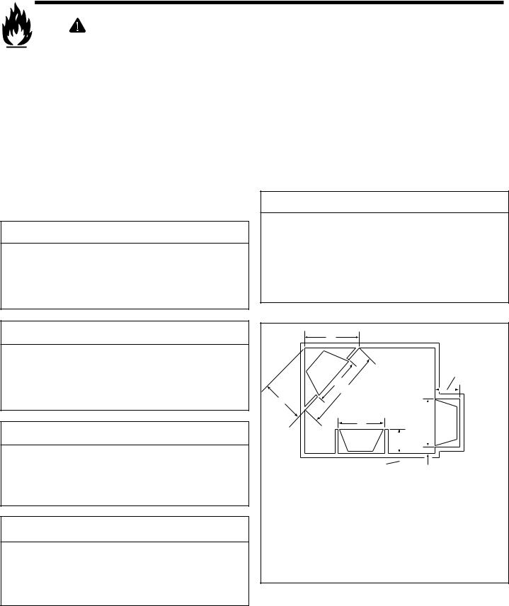
A. Selecting Heater Location
Several options are available to you when choosing a location for your heater. This heater may be used as a room divider, installed along a wall, across a corner or used in an exterior chase. See Figure 3.1. This heater may be installed directly on the fl oor, carpet or raised on a hearth.
 DANGER
Electrocution Risk
•NEVER locate this heater where it may fall into a bathtub or other water container.
•Contact local building administrator for information on bathroom intallations.
 WARNING
Fire Risk!
•Prevent contact with sagging, loose insulation.
•Do NOT install against vapor barriers or exposed insulation.
 WARNING
Do NOT use this heater if any part has been under water. Immediately call a qualified service technician to inspect the heater and to replace any part of the control system which has been under water.
 WARNING
Fire Risk
•Comply with all minimum clearances to combustibles as specifi ed.
Failure to comply may cause fi re.
B. Clearances
Figure 3.1 shows all clearances that must be maintained around the heater.
 WARNING
Fire Risk
Due to high temperature, this heater should be located out of high traffic areas.
•Keep combustible materials such as furniture, pillows, bedding, papers, clothes and curtains at least 12 in. (305 mm) from the front of the heater.
|
|
D |
|
|
|
|
|
|
|
|
|
|
|
|
|
|
|
|
|
|
|
|
|
14 in. |
|
|
|
|
A |
|
|
|
|
|
|
(356 mm) |
||
|
|
|
|
|
|
|
|
|
|
|
|
|
C |
|
B |
|
|
|
|
|
|
|
|
|
|
|
|
|
|
|
|
|
|
|
||||
|
|
|
|
|
|
|
|
|
|
|
||
|
|
|
|
|
|
|
|
|
|
|
||
|
|
|
|
|
|
|
|
|
|
|
|
|
|
|
|
|
A |
|
|
A |
|
|
|||
|
|
|
|
14 in. |
|
|
|
|
|
|
|
|
|
|
|
|
|
|
1 in. (26 mm) min. |
||||||
|
|
|
|
|
|
|||||||
|
|
|
|
(356 mm) |
||||||||
|
|
|
|
|
|
|
|
|
||||
|
|
|
|
|
|
|
|
|
|
|
||
|
Model |
|
|
A |
|
B |
|
C |
|
D |
||
|
CF550E |
|
in. |
36-1/4 |
|
45 |
22-1/2 |
31-7/8 |
||||
|
|
|
|
|
|
|
|
|
|
|
|
|
|
Series |
|
mm |
921 |
|
1143 |
572 |
|
810 |
|||
|
CF750E |
|
in. |
41-1/8 |
|
50 |
25 |
|
35-3/8 |
|||
|
|
|
|
|
|
|
|
|
|
|
|
|
|
Series |
|
mm |
1045 |
|
1270 |
635 |
|
899 |
|||
Figure 3.1 Heater Locations
Heat & Glo • CRESTFIRE Series Electric Fireplace • 4030-239 Rev J • 04/05 |
7 |
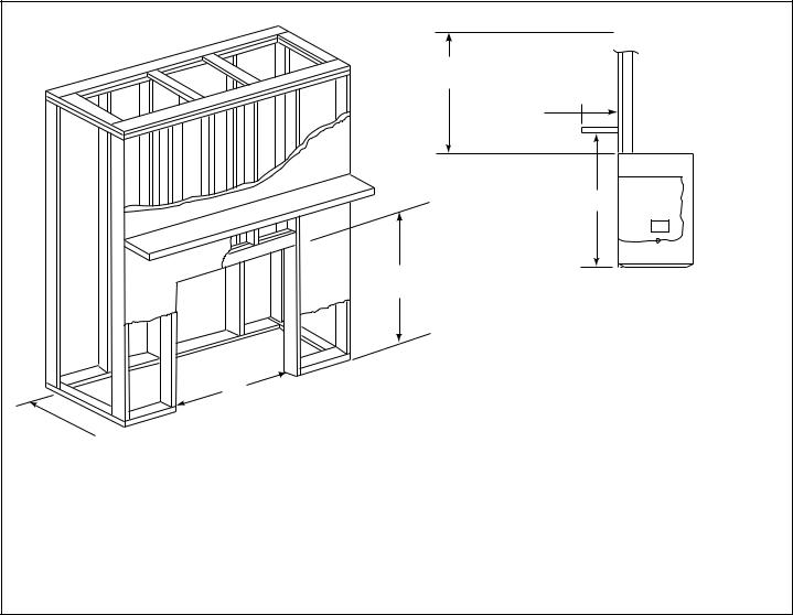
C. Framing
Figure 3.2 shows a typical framing (using 2 x 4 lumber) of the heater, assuming combustible materials are used. All required clearances to combustibles around the heater must be adhered to.
(CEILING)
14 in.
(356 mm) 
30 in. min.
(762 mm)
3/4 in. - 12 in.  (19 mm - 305 mm)
C
B*
(header height)
A*
*If using the PBT or BKT Cabinet Trim Kits, increase the width (A) by 1-1/4 in. (32 mm) and header height (B) by 5/8 in. (16 mm).
Mantel height listed is measured from the BASE of the heater.
Model |
|
A |
B |
C |
CF550E |
in. |
36-1/4 |
31-1/4 |
31-1/2 |
Series |
mm |
921 |
794 |
800 |
CF750E |
in. |
41-1/4 |
34-7/8 |
35 |
|
|
|
|
|
Series |
mm |
1048 |
886 |
889 |
Figure 3.2 Framing the Heater
8 |
Heat & Glo • CRESTFIRE Series Electric Fireplace • 4030-239 Rev J • 04/05 |
4 |
Wiring |
|
|
|
|
|
|
|
|
||
|
|
|
|
|
|
|
|
WARNING |
|
WARNING |
|
|
|
Shock Risk |
|
Shock Risk |
|
|
|
Improperly grounded outlets could cause |
|
Fire Risk |
|
|
|
electrical shock. |
|
Improperly protected power cords could |
|
|
|
• Always use properly grounded, fused and |
|
cause electrical shock or fi re. |
|
|
|
polarized outlets. |
|
• Do not pinch the cord or lay against a |
|
|
|
• Always use ground fault protection where |
|
sharp object. |
|
|
|
required by electrical code. |
|
• Do not cover the cord with carpeting, throw |
|
|
|
|
|
rugs or runners. |
|
|
|
|
|
||
|
|
|
|
• Secure and arrange cord to avoid a |
|
|
Note: Follow all national and local electrical codes. |
|
tripping hazard. |
||
|
|
|
|
|
|
|
|
|
|
|
|
|
Note: This heater must be electrically wired and grounded |
|
WARNING |
||
|
in accordance with local codes or, in the absence of local |
|
|||
|
codes, with National Electric Code ANSI/NFPA 70-latest |
|
Shock Risk |
||
|
edition or the Canadian Electric Code, CSA C2.1 as |
|
|||
|
|
Improperly grounded outlets could cause |
|||
|
appropriate. |
|
|||
|
|
electrical shock. |
|||
|
|
|
|
||
All wiring must be done by a qualified electrician. |
|
• Always use properly grounded, fused and |
|||
|
polarized outlets. |
||||
Use appropriate wire to meet local and national |
|
• Always used ground fault protection where |
|||
codes for rated power consumption. |
|
required by electrical code. |
|||
|
|
|
|
|
|
CAUTION
Label all wires prior to disconnection when servicing controls. Wiring errors can cause improper and dangerous operation. Verify proper operation after servicing.
CAUTION
Disconnect remote controls during your extended absence. This will prevent accidental operation of the heater.
A. 120VAC Wall Outlet Installation
•The heater is The heater is wired from factory with a polarized plug.
•For ease of electrical hook up, you may wish to install the heater near an existing outlet. A 15 amp, 120 volt circuit is required. A dedicated circuit is preferred but not essential in all cases. A dedicated circuit will be required if, after installation, the circuit trips or fuse blows on a regular basis when the heater is operated. Additional appliances on the same circuit may exceed the current rating of the circuit breaker.
•Before plugging heater into wall outlet, make sure all control switches are in the “OFF” position. To access the controls, lift up on the lower grille panel and rotate it forward.
•If the power cord is not being used, go to Step B below. If the cord does not reach the outlet, a No. 16-AWG minimum wire size extension cord rated for a minimum of 1875 watts may be used.
B. 120VAC Hardwire Installation
(Minimum 14 gauge two conductor wire, non-metallic sheathing with ground.)
•Turn off circuit breaker.
•Access knockout.
•Disconnect black and white wires between the heater and plug. Remove the power cord. Remove the electrical knockout and install the cable clamp (not provided) onto the hole. Remove the connectors on the wires from the heater and strip them back 1/2 in.
•Feed 8 in. of service wire through cable clamp (not provided) and secure.
•Connect black and white wires of the heater to the black and white wires from the service. Connect green (ground) wire from heater to the ground of the service.
See Figure 4.1.
•Wall switch wiring (see below) is to be done at this time.
•Use a 4 in. cover plate (not provided) over access hole if required.
•Remove the protective cover by cutting the tape located on the outer perimeter.
Heat & Glo • CRESTFIRE Series Electric Fireplace • 4030-239 Rev J • 04/05 |
9 |
 Loading...